The document presents the design and implementation of a circularly polarized patch antenna array for wireless power transmission at 5.8 GHz, aimed at optimizing rectenna systems. It discusses the performance metrics of the designed antenna array, including a directivity of 11 dB and a gain of 6 dB, validated through fabrication and measurement techniques. The research emphasizes the importance of antenna choice in rectenna applications and the design process's role in enhancing power conversion efficiency.
![TELKOMNIKA, Vol.17, No.5, October 2019, pp.2186~2193
ISSN: 1693-6930, accredited First Grade by Kemenristekdikti, Decree No: 21/E/KPT/2018
DOI: 10.12928/TELKOMNIKA.v17i5.11476 ◼ 2186
Received October 16, 2018; Revised April 6, 2019; Accepted May 3, 2019
A new configuration of patch antenna array for
rectenna array applications
A. Taybi*1
, A. Tajmouati2
, J. Zbitou3
, L. El Abdellaoui4
, M. Latrach5
, A. Errkik6
1,2,3,4,6
LMEET, FST of Settat, Hassan 1st
University, Settat, Morocco
5
Microwave Group ESEO Angers, France
*Corresponding author, e-mail: taybi.abdellah@gmail.com
Abstract
The performance and advantages of microstrip patch antennas made them a field of interest for
wireless power transmission applications, especially for rectenna systems where the choice of the antenna
is a crucial step. In this paper, a 5.8 GHz circularly polarized patch antenna has been designed and
fabricated, then mounted by using 4 elements to achieve an antenna array to enhance the captured power
to be converted by the rectifier circuit. The antenna array is well matched at 5.8 GHz in terms of reflection
coefficient and has a directivity of 11 dB and a gain of 6 dB. Results have been confirmed by fabrication.
Keywords: antenna array, patch antenna, rectenna, wireless power transmission
Copyright © 2019 Universitas Ahmad Dahlan. All rights reserved.
1. Introduction
Recent years have been characterized by a massive development of a wide range of
portable electronic devices, not only in the consumer field, such as smartphones or tablets, but
also in industrial applications, such as wireless sensor networks [1-3] or in medical
applications [4]. The general trend is to move more and more towards miniaturization of devices
in order to facilitate their portability and integration into the everyday environment. One of
the most sensitive problems to be solved is the energy source of these devices. Nowadays,
the development of power transmission system by microwave beams [5] is attracting new
attention in many applications.
The wireless energy transfer [6] is a process that takes place in any system where
electrical energy is transmitted from a power source to an electrical load, without involving
wires. Wireless power transmission is ideal in cases where instantaneous or continuous energy
transfer is needed, whereas wired connections are inconvenient, hazardous, or impossible.
Figure 1 shows the overall synoptic diagram of a Wireless Power Transmission (WPT) system.
This system is based on three operations: the conversion of electrical energy into microwaves,
the transmission of these microwaves based on the property of an electromagnetic wave to be
able to transport energy, and finally their conversion into electricity after reception which
consists on rectifying (after filtering) the currents produced in an antenna by a high frequency
diode, the result is a continuous voltage. The device used is called a Rectenna [7-11]
(rectifier + antenna) which is a key element of the power transmission system.
Figure 1. Wireless power transmission system](https://image.slidesharecdn.com/711476-200813062743/85/A-new-configuration-of-patch-antenna-array-for-rectenna-array-applications-1-320.jpg)
![TELKOMNIKA, Vol.17, No.5, October 2019, pp.2186~2193
ISSN: 1693-6930, accredited First Grade by Kemenristekdikti, Decree No: 21/E/KPT/2018
DOI: 10.12928/TELKOMNIKA.v17i5.11476 ◼ 2186
Received October 16, 2018; Revised April 6, 2019; Accepted May 3, 2019
A new configuration of patch antenna array for
rectenna array applications
A. Taybi*1
, A. Tajmouati2
, J. Zbitou3
, L. El Abdellaoui4
, M. Latrach5
, A. Errkik6
1,2,3,4,6
LMEET, FST of Settat, Hassan 1st
University, Settat, Morocco
5
Microwave Group ESEO Angers, France
*Corresponding author, e-mail: taybi.abdellah@gmail.com
Abstract
The performance and advantages of microstrip patch antennas made them a field of interest for
wireless power transmission applications, especially for rectenna systems where the choice of the antenna
is a crucial step. In this paper, a 5.8 GHz circularly polarized patch antenna has been designed and
fabricated, then mounted by using 4 elements to achieve an antenna array to enhance the captured power
to be converted by the rectifier circuit. The antenna array is well matched at 5.8 GHz in terms of reflection
coefficient and has a directivity of 11 dB and a gain of 6 dB. Results have been confirmed by fabrication.
Keywords: antenna array, patch antenna, rectenna, wireless power transmission
Copyright © 2019 Universitas Ahmad Dahlan. All rights reserved.
1. Introduction
Recent years have been characterized by a massive development of a wide range of
portable electronic devices, not only in the consumer field, such as smartphones or tablets, but
also in industrial applications, such as wireless sensor networks [1-3] or in medical
applications [4]. The general trend is to move more and more towards miniaturization of devices
in order to facilitate their portability and integration into the everyday environment. One of
the most sensitive problems to be solved is the energy source of these devices. Nowadays,
the development of power transmission system by microwave beams [5] is attracting new
attention in many applications.
The wireless energy transfer [6] is a process that takes place in any system where
electrical energy is transmitted from a power source to an electrical load, without involving
wires. Wireless power transmission is ideal in cases where instantaneous or continuous energy
transfer is needed, whereas wired connections are inconvenient, hazardous, or impossible.
Figure 1 shows the overall synoptic diagram of a Wireless Power Transmission (WPT) system.
This system is based on three operations: the conversion of electrical energy into microwaves,
the transmission of these microwaves based on the property of an electromagnetic wave to be
able to transport energy, and finally their conversion into electricity after reception which
consists on rectifying (after filtering) the currents produced in an antenna by a high frequency
diode, the result is a continuous voltage. The device used is called a Rectenna [7-11]
(rectifier + antenna) which is a key element of the power transmission system.
Figure 1. Wireless power transmission system](https://image.slidesharecdn.com/711476-200813062743/75/A-new-configuration-of-patch-antenna-array-for-rectenna-array-applications-1-2048.jpg)
![TELKOMNIKA ISSN: 1693-6930 ◼
A new configuration of patch antenna array for rectenna array applications (A. Taybi)
2187
Indeed, in the design process of a global wireless energy transport system, the last
step, the Rectenna, is essential and must therefore be optimized in order to achieve optimal
conversion efficiency. To this must be added technological and environmental constraints
such as:
- Elementary rectenna networking strategy to limit the impact of the fragility of
the rectifier diodes.
- Compliance with the international safety standard on electromagnetic radiation.
- Good environmental integration combined with a transparent property of the rectenna against
solar radiation to make the reception surface useful.
- Ergonomic design of a manufacturable rectenna architecture (essential for the assembly of
large rectenna structures).
The rectenna is typically constituted by the association of an antenna (or antenna array)
with a rectifier [12] system (a Schottky diode [13]) and filtering elements. A typical rectenna
block diagram is shown in Figure 2. The wireless energy can be collected by the antenna
attached to rectifying diodes through filters and matching circuit (Load matching between
antenna and circuit). The rectifying diodes convert the received wireless energy into DC power.
Figure 2. Block diagram of rectenna circuit
The receiving antenna will be the one that will allow us to collect microwave energy.
There are no particular restrictions on the choice of antenna. It can be a dipole [14],
a patch [15, 16], the technology used can be wired, plated or other. However, it is necessary to
define in advance how to integrate the "rectification" module. For applications involving Wireless
Power Transmission, the planar or Micro strip antennas [17, 18] are widely used. This type of
antenna generally consists of a ground plane, one or more layers of dielectric substrates and
one or more conductive radiating elements having different shapes: square, rectangular,
triangular, circular, elliptical or other more complex shapes. Printed antennas are designed to
meet the requirements of technological evolution, which is also leading to the miniaturization of
electronic devices and telecommunications systems. With their small dimensions,
their performance, their flexibility makes them particularly adaptable to mobile devices (satellite,
aircraft, boat) and their suppleness which allows them to fit any shape of surface (flat or
shaped), these antennas have proven their efficiency and tend to replace traditional antennas
permanently. In addition, they are easy to fabricate, low cost, compact and they have the ability
to integrate with microwave integrated circuits technology.
To optimize the power collected by the system, it is necessary to maximize the captured
RF power. To do this, we can either increase the surface area of the antennas with
the disadvantage of shifting the bandwidth to low frequencies, or keep the benefit of the same
antennas by combining several in a network [19-23], which is the subject of extensive research.
The technique proposed in this work is useful for collecting maximum power from antenna block
to feed directly the rectification device. To this purpose, we have first designed a single element
circularly polarized patch antenna at 5.8 GHz, printed on an FR4 substrate having dielectric
constant εr=4.4, substrate thickness h = 1.6 mm and the loss tangent is 0.025. Then, we have
mounted the antenna on a four elements array in order to improve the effective radiated power,
the directivity, and the gain.](https://image.slidesharecdn.com/711476-200813062743/85/A-new-configuration-of-patch-antenna-array-for-rectenna-array-applications-2-320.jpg)
![◼ ISSN: 1693-6930
TELKOMNIKA Vol. 17, No. 5, October 2019: 2186-2193
2188
2. Single Element Antenna Design
A simple microstrip antenna consists of a very thin metal patch of dimensions L x W
placed on a dielectric substrate fixed on a metallic ground plane as shown in Figure 3.
The patch is actually a bit larger electrically than its physical dimensions due to the fringing
fields and the difference between electrical and physical size is mainly dependent on the PC
board thickness and dielectric constant of the substrate. The antenna can be considered as a
resonant cavity transmission line with two open ends at a length λ/2 where the fields at
the edges of the patch and the ground plan are exposed to the outside space and create
the radiation. The finished dimensions of the radiating element (length and width) cause the field
lines at the edges of the patch.
Figure 3. Rectangular micro strip antenna configuration
The antenna dimensions are calculated theorically as follow:
2.1.Calculation of Width (W)
For an effective radiator, practical width of the patch antenna that leads to good
radiation efficiencies is given by [24]:
𝑊 =
𝐶0
2𝐹0
√
2
1+ 𝜀 𝑟
(1)
where C0 is the free-space velocity of light i.e. 3×10⁻⁸ m/s and εr is the dielectric constant
of material.
2.2.Calculation of Effective Dielectric Constant εreff
The value of effective dielectric constant is less than dielectric constant of the substrate,
because of the fringing fields are not confined in dielectric substrate around the periphery of
the patch only, but is also spread in the air. The value of this effective dielectric constant is
given by [24]:
εreff =
𝜀 𝑟+ 1
2
+
𝜀 𝑟− 1
2
[1 + 12
ℎ
𝑊
]-1/2
(2)
2.3.Calculation of Length (L)
The length of the patch determines the resonance frequency thus it is a critical factor for
narrowband patch. Since it is not possible to accurately account the fringing field the results are
not definite. Below is the equation to calculate the length of the patch [24]:
𝐿 =
𝜆 𝑒𝑓𝑓
2
− 2𝛥𝐿 (3)
where ΔL is the length extension because of fringing field, which can be calculated as follow:](https://image.slidesharecdn.com/711476-200813062743/85/A-new-configuration-of-patch-antenna-array-for-rectenna-array-applications-3-320.jpg)
![TELKOMNIKA ISSN: 1693-6930 ◼
A new configuration of patch antenna array for rectenna array applications (A. Taybi)
2189
𝛥𝐿 = 0.412 ℎ
(𝜀 𝑟𝑒𝑓𝑓+0.3)(
𝑊
ℎ
+ 0.264)
(𝜀 𝑟𝑒𝑓𝑓−0.258)(
𝑊
ℎ
+ 0.8)
(4)
2.4. Feeding Mechanisms
A recurring problem in the design of printed antennas is the choice of excitation
technique. Coaxial probe excitation is possible, but it is often preferable to use micro strip lines
that allow several elements to be supplied at the same time, particularly in the case of antenna
array. We will distinguish several types of power supplies whose main ones are: excitation by
coaxial probe, by micro strip line, by proximity, and by coupling through a slot in the ground
plane. The proximity feeding is done from two superposed substrates of different permittivities.
The upper substrate will be chosen for low permittivity to promote radiation, while the lower
substrate will be high permittivity to concentrate the electromagnetic field between the printed
line and the ground plane. The aperture coupling method is considered as a solution to isolate
the printed supply line from the radiating element by cutting a gap in the ground plane so that
the line can be coupled to the radiating block.
This solution, which requires three levels of metallization, is attractive because it allows
active components to be integrated into the printed line without damaging the antenna's
radiation given the presence of the ground plane between the two. Unfortunately, parasitic rear
radiation can occur, especially if you work at a frequency close to the resonance of the coupling
slot. Finally, the technique used in this paper is to feed the patch antenna by micro strip line,
the advantage of feeding by micro strip line on the same plane is the simplicity of
implementation and easiness of fabrication. Only one substrate is used here, and we can match
the impedance by using several technics.
2.5. Antenna Design
The electromagnetic behaviour of an antenna is complex and there are many
approximation formulas in the literature that allow to approach a behaviour in a frequency band.
Optimization is essential, it can be done either by measurement alone (but this requires quite
expensive equipment) or by using an electromagnetic simulator to reduce the measurement
steps. However, these softwares are time-consuming to compute since they use the digitized
Maxwell equations. Nowadays several simulation tools have emerged, each has its advantages
and limitations, but overall they all allow the design and simulation of antennas and radiating
structures, the calculation of RF properties such as reflection coefficients, efficiencies, near and
far field values, gains etc. Among these softwares, Advanced Design System (ADS) [25] was
chosen during the work of simulation of this structure. Through its Momentum tool, it allows to
perform an electromagnetic simulation based on the finite element grid of the patch and
presents the gain and directivity values as well as the two and three-dimensional radiation
pattern. In addition, it features a very advanced and intuitive interface for design and
visualization of results. Figure 4 shows the geometry of the proposed patch antenna which
operate at 5.8 GHz.
The reflection coefficient commonly referred to as S11 describes the ratio between
the reflected wave and the incident wave at the antenna input. The study of the reflection
coefficient is very rich in information because it provides us with information on the antenna's
behavior in terms of bandwidth and level of adaptation, which are two essential characteristics
of good or bad functioning. The bandwidth can be defined according to several criteria: with
reference to the reflection coefficient (|S11| ≤ -10 dB) or almost equivalent to the Stationary
Wave Ratio (SWR ≤ 2), or in relation to the efficiency (Eff ≥ 80% for example). Of course,
the chosen reference level can change from one application to another. While within
the antenna scientific community it is generally considered that an antenna is well matched
when |S11| ≤ -10 dB, in practice this requirement is often reduced when considering antennas
for radiocommunication terminals (where a criterion of |S11| ≤ -5 dB is common). In our case,
the antenna performance in terms of impedance matching is depicted in Figure 5. It’s clear from
the graph that the antenna is well matched at 5.8 GHz.](https://image.slidesharecdn.com/711476-200813062743/85/A-new-configuration-of-patch-antenna-array-for-rectenna-array-applications-4-320.jpg)
![◼ ISSN: 1693-6930
TELKOMNIKA Vol. 17, No. 5, October 2019: 2186-2193
2190
Figure 4. The proposed
patch antenna
Figure 5. Simulated reflection coefficient
versus frequency
3. Antenna Array Design
In rectenna application, it is necessary to design antennas with high directive
characteristics to meet the demands of long-distance links. Hence, one element antenna could
not respond to this requirement. To overcome this problem, antenna arrays are suggested in
order to benefit from the advantage of superimposing the radiation of each element in the same
direction to increase the overall gain and directivity of the antenna.
Several constraints can influence the design of antenna arrays. Mutual coupling, input
impedance matching of the supply line and distance between the elements are the most
important factors to consider when designing. The spacing between the network elements
directly affect the radiation pattern and gain. If the elements are too close to each other, a
coupling phenomenon reduces the gain value and when they are too far away, that affect
the principal lobe and therefore reduce the directivity. In addition, the input impedance matching
to 50 Ohm is necessary to ensure proper operation of the antenna. The line dimensions are
calculated using Agilent's Lincalc software [25]. To feed a two-element antenna array,
a T-shaped junction is used. There are several configurations of the T-junction with different
calculation methods. The example used is the case where the input impedance is well matched,
however, the output impedances are terminated with the double value of the input impedance.
In this situation, the value of the input impedance is 50 Ohms, then the output impedance will
have the value of 100 Ohms.
The simulation results of the return loss (S11) of the four-elements antenna array
Figure 6 are shown in Figure 7 (a). The Momentum solver provided by Advanced Design
System have been used and an FR4 substrate having dielectric constant εr=4.4, substrate
thickness h=1.6 mm and the loss tangent is 0.025 have been employed. We can conclude, from
the graph, that the four-elements array is well matched at 5.8 GHz and that the effects of
the coupling between the resonators are minimal due to the chosen distance between them.
The other performance indicators are depicted in Figure 7 (b), the purpose of this work have
been reached by achieving the desired gain and directivity at 5.8 GHz.
Figure 6. The proposed patch antenna array](https://image.slidesharecdn.com/711476-200813062743/85/A-new-configuration-of-patch-antenna-array-for-rectenna-array-applications-5-320.jpg)
![◼ ISSN: 1693-6930
TELKOMNIKA Vol. 17, No. 5, October 2019: 2186-2193
2192
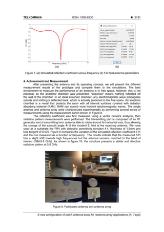
(a) (b)
Figure 9. Simulated and measured results. (a) S11 versus frequency
(for Single element antenna) (b) S11 versus frequency (for Antenna Array)
Figure 10. The measured E-plan antenna array radiation pattern at 5.8 GHz
for azimuth plan of 0, 45 and 90°
5. Conclusion
The work presented in this paper is devoted to the design, optimization, fabrication and
measurement of a circular polarized patch antenna array operating at 5.8 GHz of the Industrial
Scientific Medical (ISM) band. The aim of this study is to cover the needs in applications
involving wireless power transmission especially for Rectenna implementations. Firstly, we have
started with a single element antenna validated by simulations and measurements, then moved
on to an array configuration by associating four elements of the proposed patch antenna in
order to enhance the coverage, gain and directivity. Consequently, the rectenna performances
are significantly improved. Simulation results have been confirmed by measurements, a gain of
6 dB and directivity of 11 dB have been reached. The measurement results demonstrate that we
have a good matching input impedance at 5.8 GHz with a directive radiation pattern.
The proposed antenna array will be suitable for wireless transmission applications with high
gain and circular polarization.
References
[1] Al Agha K, Bertin M, Dang T, Guitton A, Minet P, Val T, et al. Which Wireless Technology for
Industrial Wireless Sensor Networks? The Development of OCARI Technology. IEEE Trans Ind
Electron. 2009; 56(10): 4266–4278.
[2] Gungor VC, Hancke GP. Industrial Wireless Sensor Networks: Challenges, Design Principles, and
Technical Approaches. IEEE Trans Ind Electron. 2009; 56(10): 4258–4265.
[3] Tan YK, Panda SK. Optimized Wind Energy Harvesting System Using Resistance Emulator and
Active Rectifier for Wireless Sensor Nodes. IEEE Trans Power Electron. 2011; 26(1): 38–50.
[4] Mahfouz M, To G, Kuhn M. No Strings Attached. IEEE Microw Mag. 2011; 12(7): S34–48.](https://image.slidesharecdn.com/711476-200813062743/85/A-new-configuration-of-patch-antenna-array-for-rectenna-array-applications-7-320.jpg)
![TELKOMNIKA ISSN: 1693-6930 ◼
A new configuration of patch antenna array for rectenna array applications (A. Taybi)
2193
[5] Brown WC. The History of Power Transmission by Radio Waves. IEEE Trans Microw Theory Tech.
1984; 32(9): 1230–1242.
[6] Shams KMZ, Ali M. Wireless Power Transmission to a Buried Sensor in Concrete. IEEE Sens J.
2007; 7(12): 1573–1577.
[7] Zbitou J, Latrach M, Toutain S. Hybrid rectenna and monolithic integrated zero-bias microwave
rectifier. IEEE Trans Microw Theory Tech. 2006; 54(1): 147–152.
[8] Matsunaga T, Nishiyama E, Toyoda I. 5.8 GHz Stacked Differential Rectenna Suitable for
Large-Scale Rectenna Arrays with DC Connection. IEEE Trans Antennas Propag. 2015; 63(12):
5944–5949.
[9] Richelli A, Colalongo L, Tonoli S, Kovacs-Vajna ZM. A 0.2-1.2V DC/DC Boost Converter for Power
Harvesting Applications. IEEE Trans Power Electron. 2009; 24(6): 1541–1546.
[10] Taybi A, Tajmouati A, Zbitou J, Errkik A, Latrach M, El abdellaoui L. A New Configuration of a High
Output Voltage 2.45 GHz Rectifier for Wireless Power Transmission Applications. Telecommun
Comput Electron Control J. 2018; 16(5): 1939–1946.
[11] Assimonis SD, Bletsas A. Energy harvesting with a low-cost and high efficiency rectenna for
low-power input. In: 2014 IEEE Radio and Wireless Symposium (RWS). 2014; 229–231.
[12] Merabet B, Cirio L, Takhedmit H, Costa F, Vollaire C, Allard B, et al. Low-cost converter for
harvesting of microwave electromagnetic energy. In: 2009 IEEE Energy Conversion Congress and
Exposition. 2009; 2592–2599.
[13] HSMS-282X series. Surface mount RF Schottky barrier diode. Agilent Technol., Palo Alto, CA, Tech.
Data. 2001.
[14] Gao F, Zhang F, Lu L, Ni T, Jiao Y. Low-Profile Dipole Antenna with Enhanced Impedance and Gain
Performance for Wideband Wireless Applications. IEEE Antennas Wirel Propag Lett. 2013; 12:
372–375.
[15] Khidre A, Lee K, Yang F, Elsherbeni AZ. Circular Polarization Reconfigurable Wideband E-Shaped
Patch Antenna for Wireless Applications. IEEE Trans Antennas Propag. 2013; 61(2): 960–964.
[16] Shen S, Chiu C, Murch RD. A Dual-Port Triple-Band L-Probe Microstrip Patch Rectenna for Ambient
RF Energy Harvesting. IEEE Antennas Wirel Propag Lett. 2017; 6: 3071–3074.
[17] Lee K, Yang SLS, Kishk AA. Dual and Multiband U-Slot Patch Antennas. IEEE Antennas Wirel
Propag Lett. 2008; 7: 645–647.
[18] Lee KF, Luk KM. Microstrip Patch Antennas. London. U.K.: Imperial College Express, ch. 10. 2001.
[19] Yu-Jiun Ren, Kai Chang. 5.8 GHz circularly polarized dual-diode rectenna and rectenna array for
microwave power transmission. IEEE Trans Microw Theory Tech. 2006; 54(4): 1495–502.
[20] Yang X, Geyi W, Sun H. Optimum Design of Wireless Power Transmission System Using Microstrip
Patch Antenna Arrays. IEEE Antennas Wirel Propag Lett. 2017; 16: 1824–1827.
[21] Taybi A, Ghaloua A, Tajmouati A, Mandry R, El Abdellaoui L, Latrach M. A New Design of Rectenna
Array with High Performances. In: Proceedings of the 2nd
International Conference on Computing
and Wireless Communication Systems. New York, NY, USA: ACM. 2017; 1:(1): 1-7.
[22] Morabito AF. Power Synthesis of Mask-Constrained Shaped Beams Through Maximally-Sparse
Planar Arrays. Telecommun Comput Electron Control J. 2016; 14(4): 1217–1219.
[23] Morabito AF, Nicolaci PG. Optimal Synthesis of Shaped Beams Through Concentric Ring Isophoric
Sparse Arrays. IEEE Antennas Wirel Propag Lett. 2017; 16: 979–982.
[24] Balanis CA. Antenna Theory, Analysis and Design. 3rd
ed. New York, NY, USA: John Wiley
& Sons. 2005.
[25] Advanced Design System (ADS). http://www.home.agilent.com/agilent/home.jsp](https://image.slidesharecdn.com/711476-200813062743/85/A-new-configuration-of-patch-antenna-array-for-rectenna-array-applications-8-320.jpg)