This document describes a hybrid Kalman filtering approach for estimating the state of charge (SOC) of lithium-ion batteries used in low-powered microcontrollers. An electrical equivalent circuit battery model is developed and its parameters are identified through discharge cycle simulations and experiments. Extended Kalman filtering is then used to estimate SOC with errors less than 1% based on simulations and experiments. The algorithm is implemented on an STM microcontroller, where a hybrid Coulomb counting and EKF approach is used to estimate SOC with less than 0.5% error to suit the microcontroller's limited memory.
![A Hybrid Kalman Filtering for State of Charge
Estimation of Lithium-Ion Battery Used in Low-
Powered Microcontroller: CCM-EKF Approach
Hong Vin Koay
Department of Electrical Engineering
University of Malaya
Kuala Lumpur, Malaysia.
koayhongvin@gmail.com
Joon Huang Chuah
Department of Electrical Engineering
University of Malaya
Kuala Lumpur, Malaysia.
jhchuah@um.edu.my
Kong Yew Tan
AMS IC Design Group, Microsystem
MIMOS Berhad
Kuala Lumpur, Malaysia.
kongyew.tan@mimos.my
Abstract—A new technique that aimed to be flashed into a
low-power microcontroller to estimate the state of charge (SOC)
of lithium-ion battery is introduced. First, an electrical
equivalent model is developed to simulate and model the
behaviour of the battery. The battery used in this work is
Panasonic NCR18650B and 2RC model is chosen to capture the
slow and fast response of the battery. The parameters are
identified through the discharging cycle with the help of
MATLAB Simulink Design Optimization (SDO). Then, the
model is verified through simulations and experiments. Once the
model is verified to be within an acceptable range, it is then set
to run several drive cycles, including constant current discharge
(CCD) and hybrid pulse power characterization (HPPC) test. It
is shown that the SOC estimation error using Extended Kalman
Filter (EKF) is <1% in both simulation and experiment. Finally,
the algorithm is flashed into an STM chip and then external
circuits are used to collect the real-world data. The SOC is then
estimated. A hybrid Columb Counting Method and EKF SOC
estimation are introduced to suit the limited flash memory of the
chip. The on-chip SOC estimation error is <0.5%.
Keywords—Extended Kalman Filter, Lithium-ion Battery,
Battery Management System, State of Charge Estimation
I. INTRODUCTION
The demand for limited fossil fuels has never come to an
end. With the growing concern of the carbon dioxide
emission, an alternative for clean energy and storage systems
were highly researched and developed. These clean energy
applications have grown when Electronic Vehicles (EVs)
slowly taken over the market, which has made the battery
becoming the most prominent energy storage device [1].
Lithium-ion, or commonly known as li-ion, is a promising
power source for EVs due to its high energy density and long
cycle life [2, 3]. Because of its popularity, the price of
lithium-ion battery (LiB) continues to decline, making it a
much competitive choice for EV applications [4]. With these
great benefits, the safety and reliable operation of a battery
pack should be ensured. Thus, it is crucial to make sure that
the Battery Management System (BMS) can manage the state
of charge (SOC) of batteries efficiently. An accurate model
of the battery is needed, especially the SOC of a battery pack
should be accurately estimated [5].
However, it is difficult in determining and estimating the
parameters as they are interdependent and varies among
different batteries [6]. The exact measurement of SOC for
battery plays an important role when charging and
discharging batteries [7]. There exist several methods in
estimating SOC of a battery [8, 9]. Among those methods, the
Coulomb counting method (CCM) is the commonly used
technique. It integrates the measured battery current with
respect to time and it is then used to determine the battery
SOC. Although this method can do the task, the accuracy of
the estimation is highly dependent on the prior knowledge of
initial SOC and may accumulate errors from noise [10]. Other
methods, including the Open Circuit Voltage (OCV) method,
are suffice, but it needs a long relaxation time, making it to
be not suitable for real-time applications [11].
With the advancement in computation technology, several
intelligent approaches have been introduced as a replacement
for CCM and OCV method and offered higher accuracy in
SOC estimation. Among them, the neural network method
and Kalman Filter (KF) method have been reported to have
higher accuracy.
Although LiB provides a lot of favourable characteristics
and advantages, the main drawback is the cost of materials
and manufacturing [12] and limited use cycle due to the
ageing process, which translates into more waste. Thus, a
better implemented BMS would increase the lifetime.
Cost of implementing highly real-time and accurate model
would be not justified when dealing with only several
batteries for minimal project implementation. As for colossal
project implementation such as EV, the manufacturers are
looking for 300,000 cycle range for Hybrid EV and 1,000
cycle range for Battery EV [13]. All of this translates into the
need for accurate yet promising with minimal cost of
estimation and monitoring of battery.
In this work, the focus is on further improving the accuracy
of estimating of SOC for LiB with the use of Extended
Kalman Filter (EKF). EKF is deemed to be computationally
expensive but thanks to its accuracy, it is justifiable especially
for broad implementation, such as EV. In this project, the
balance between accuracy and the computational requirement
is done to make sure it fit for smaller project implementation.
EKF is very dependent on the type of battery and thus this
project also investigates if this technique fits well for LiB.
Thus, many iterations of experiments shall be taken to make
sure the data is consistent. There do exist several uncertainties
and variables, such as ageing of the battery and possible over-
discharging or overcharging of the battery. This has further
increased the difficulty and accuracy of the suggested
algorithm preparing for hardware implementation.
As for hardware implementation, even though there exists
advanced BMS in the market, but they are usually not suitable
for smaller project implementation and expensive. This
project looks into the integration of the algorithm on-chip for
embedded EKF SOC estimation.
2020 IEEE 8th Conference on Systems, Process and Control (ICSPC), 11–12 December 2020, Melaka, Malaysia
978-1-7281-8860-7 ©2020 IEEE](https://image.slidesharecdn.com/ahybridkalmanfilteringforstateofchargeestimationoflithium-ionbatteryusedinlow-poweredmicrocontroller-211207071555/75/A-hybrid-kalman-filtering-for-state-of-charge-estimation-of-lithium-ion-battery-used-in-low-powered-microcontroller-ccm-ekf-approach-1-2048.jpg)
![II. LITERATURE REVIEW
Extra care should be applied in the operating conditions to
avoid thermal runaways, physical damage and ageing issue,
in order to harvest the maximum potential of LiB. Thus, a
battery management system (BMS) is needed in a precise
measure, regulate and estimate the battery packs. BMS, by
definition, means a system that is capable of managing a
battery [14].
BMS has been used in many fields. The nearest example is
portable electronic devices, such as notebook and mobile
phone, which uses BMS as well. BMS in EV, on the other
hand, is still in its ‘baby stage’ as the number of battery cells
used in EV is a hundred times higher than that of consumer
portable electronic devices.
A. State of Charge
State of Charge (SOC) is defined as the ratio of releasable
or remaining capacity to the actual capacity of the battery
[15], which could be expressed as in Eq. (1).
= × 100% 1
From eq. (1), Cremaining is the maximum available capacity
of battery after a specific period, while Cactual is the maximum
possible limit of charge of battery during the initial full
charge or discharge cycle. Cremaining is influenced by the
degradation of battery due to cycling and corrosion, and Cactual
will not achieve the rated capacity, Crated as provided by the
battery manufacturer. Cactual depends on State of Health
(SOH) of the battery as well as the discharging current rate.
SOC is represented in percentage, where 100% represents
fully charged and 0% represents fully discharged.
B. Battery Modelling
The battery model is the heart of every model-based SOC
estimation. It is used to mimic the battery behaviour. As such,
it is vital to have a reliable yet accurate model. Battery model
can be classified into Empirical Model, Electrochemical
Model (ECM), Electrical Equivalent Circuit Model (EECM),
Electrochemical Impedance Model and Data-Driven Model.
Among all, EECM is the preferable method for online SOC
estimation. EECM is simple, which requires less
computational power and it provides high compatibility for
embedded system applications.
EECM utilizes lumped discrete components, like a
capacitor, voltage source and resistor to picture the battery
dynamic behaviour [16]. In EECM, generally, a resistor
represents the discharging element, capacitor and voltage
source represents the battery OCV. Multiple RC pairs may be
found in the model with different time constants, which the
time constant stands for the diffusion process in the
electrolyte and porous electrodes, the charge transfer and
double-layer effect in the electrode [17].
EECM has a lot of variants, such as Rint [18], Randles
[19], Partnership for a New Generation of Vehicle (PNGV)
[20, 21], 1RC model / Thevenin model [22] and 2RC model
/ Dual Polarization (DP) model [23, 24].
2RC model is more preferred in online SOC estimation. It
contains two RC branches, of which describes slow and fast
transient response caused by charge transfer and diffusion of
lithium-ion battery [24]. 2RC is used to overcome the
inability of 1RC in getting the difference between
concentration polarization and electrochemical polarization,
which causes inaccurate simulation at the end of charging or
discharging [18]. In the 2RC model, battery temperature and
SOC positively influenced the parameter values.
C. Kalman Filter
Kalman filter (KF) theory was introduced in 1960 by
Rudolf Emil Kalman [25]. KF can be classified into linear
and nonlinear. Nonlinear KF includes Extended Kalman
Filter (EKF), Sigma Point Kalman Filter (SPKF), Cubature
Kalman Filter (CKF), etc. Generally, the steps in combining
battery model with KF algorithm can be shown in Fig. 1,
where there are intermediate steps.
From Fig. 1, discretization is needed as EECM contains
nonlinear partial differential equations (PDEs) and needs to
simplify the calculation. Discretization can be done with the
analytical method, integral method approximation, finite
element method, etc. Three discretization methods, which are
finite difference, finite element and differential quadrature
methods, were applied and then compared with the SP model
[26]. It is found that the differential quadrature method is the
best among all given the trade-off between low order and
accuracy. In the EECM, bilinear transformation is the
standard discretization method [27].
Then, the time domain difference equations are obtained
through a discretized battery model. It is needed for battery
parameter identification. By plugging in the identified
parameter into time-domain difference equations, the state
space representation equations are now useful for KF
algorithm.
Past studies on EKF suggested that the average error is
within 1 – 4% [28-33]. Among all KF algorithm, EKF is able
to operate well even in noisy and inaccurate initial conditions.
When utilizing KF algorithms, initial noise covariance
matrix or also known as KF tuning is an essential step in
determining the accuracy of the estimation. The performance
of the filter is set by covariance matrix P, process noise
matrix Q and measurement noise R. It is not possible to tune
the KF parameters correctly in the field of batteries, and
generally, the parameters are determined through past
experiences or experiments. The covariance matrix, P
determines the convergence behaviour, while the process
noise matrix, Q determines the model uncertainty. As for
measurement noise, R, it determines the measurement
uncertainty. The conditions of the parameters and its
consequences are summarized in Table I [27, 32].
III. METHODOLOGY
A. Battery Modelling
This work uses the 2RC model, as shown in Fig. 2.
Battery
Model
Discretization
Representation
in state space
equations
KF
Algorithm
Fig. 1. Steps in combining battery model and KF algorithm
Fig. 2. 2RC model.
R
Uoc VT
+
-
I
R2
C2
V2
R1
C1
V1
2020 IEEE 8th Conference on Systems, Process and Control (ICSPC), 11–12 December 2020, Melaka, Malaysia
978-1-7281-8860-7 ©2020 IEEE](https://image.slidesharecdn.com/ahybridkalmanfilteringforstateofchargeestimationoflithium-ionbatteryusedinlow-poweredmicrocontroller-211207071555/75/A-hybrid-kalman-filtering-for-state-of-charge-estimation-of-lithium-ion-battery-used-in-low-powered-microcontroller-ccm-ekf-approach-2-2048.jpg)
![By using simple circuit rule, the dynamic behaviour of the
system could be extracted. Applying Kirchhoff’s Voltage
Law (KVL) on the circuit in Fig. 5, the expression of terminal
voltage could be written as,
= − − − 2
KF only works on the discrete-time system and the
continuous model above has to be discretized [34]. By
converting into a discrete-time model, it makes the model
easier to implement on a modern computer which inherently
is limited to finite numerical representations of numbers and
discrete processes.
The final state-space equation is,
,
,
=
1 0 0
0 0
0 0
,
,
+
−
1 −
1 −
3
B. Battery Parameter Identification
The model used in the simulation is a 2RC model, having
six parameters to be collected. The parameters are Em, R0, τ1,
τ2, R1 and R2. These parameters are estimated through a series
of iteration. They are done through a series of curve fitting
and utilizing the Simulink Design Optimization.
C. Extended Kalman Filter
Since EKF utilizes analytic linearization of the model at
every point of time, thus, it is clear that there are some issues,
but it is still popular, thanks to its computational efficiency.
In EKF, the calculations can be split into two steps, which is
prediction and correction steps. Both steps contain three sub-
steps.
In prediction stage, the present value, is calculated
based on the prior information, . Then, the predicted state
estimate error covariance matrix, Σ , is calculated. The
system output is predicted and written as
. In correction
stage, the output prediction error is calculated and then the
estimator gain matrix (also known as Kalman gain), is
determined. The state estimate is calculated based on the
Kalman gain through the state prediction. Here, is the state
vector and is the output from the system.
The central equation of each step is shown below.
D. Software Simulation
Once the battery modelling is done, it is then used to feed
in with variable load and the battery’s output is being
compared with the output given by EKF. The error is being
calculated and being repeated several iterations, excluding
the ageing process.
The battery modelling is done when a new battery is used
as the parameter is varied slightly across batteries.
Discharging data is used for battery modelling and the
discharging cycle is specifically CCD as identification of
pulse will be made more accessible and more accurate
parameter could be obtained.
In order to collect the battery data, the charging and
discharging of the battery should be done accordingly. There
are several ways to do so. In manual data collection, the
charging and discharging is done separately with different
equipment. Another way of data collection is through battery
tester, as the battery tester is able to do the battery charging,
discharging and monitoring all together in one equipment.
E. Data Collection
The charging and discharging of battery are done through
programmable DC power supply and load.
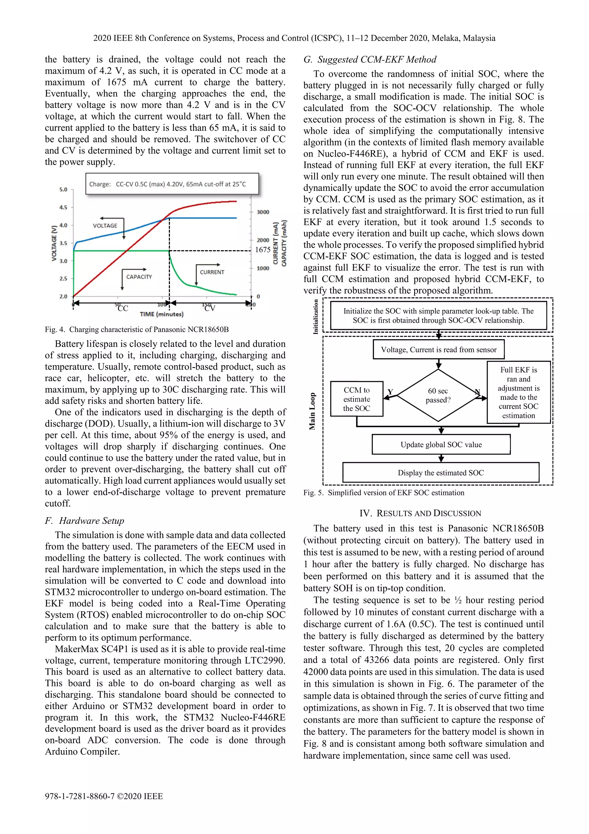
The recommended charging mode is Constant Current
(CC) – Constant Voltage (CV), at a maximum of 0.5C.
Knowing that the typical capacity of a Panasonic NCR18650
Lithium-Ion battery is 3350mAh, thus the maximum current
that should be used to charge the battery is 1675 mA. The CC
and CV region is categorized as such, where initially, when
TABLE I
COVARIANCE MATRIX, PROCESS NOISE MATRIX AND MEASUREMENT
NOISE VALUE AND ITS CONSEQUENCES
Parameter Condition Consequences
Diagonal
elements
of P, Px
Zero 1. Assumption of accurate initial values.
2. Adaptation of incorrect initial value is
slow.
High 1. Fast correction of initial parameters.
2. Unstable behavior.
Diagonal
elements
of Q, Pw
Zero 1. Assumption of perfect model.
2. No correction of states.
High 1. Increase estimation error.
2. Uncertainty of states.
Diagonal
elements
of R, Pv
Small 1. Assumption of high accuracy of
measurement sensors.
2. Calculation based on measurement,
ignoring the model.
High 1. Low Kalman Gain.
2. Correction of measurement is
reduced.
3. Estimation based on model without
corrections.
Step 1a: State-prediction time update
= | = , , |
≈ , ,
Step 1b: Error covariance time update
Σ , =
≈ Σ , + Σ
where =
, ,
,
=
, ,
Step 1c: Predict system output
= | = ℎ , , | ≈ ℎ , , ̅
Step 2a: Estimator gain matrix
= Σ , Σ , = Σ , Σ , + Σ
where =
, ,
, =
, ,
Step 2b: State-estimate measurement update
= + −
Step 2c: Error covariance measurement update
Σ , = Σ , − Σ ,
Battery Data
(Charging /
Discharging)
Battery Modelling
/ Parameter
Identification
SOC
Estimation via
EKF
Fig. 3. Software simulation procedure used in this work.
2020 IEEE 8th Conference on Systems, Process and Control (ICSPC), 11–12 December 2020, Melaka, Malaysia
978-1-7281-8860-7 ©2020 IEEE](https://image.slidesharecdn.com/ahybridkalmanfilteringforstateofchargeestimationoflithium-ionbatteryusedinlow-poweredmicrocontroller-211207071555/75/A-hybrid-kalman-filtering-for-state-of-charge-estimation-of-lithium-ion-battery-used-in-low-powered-microcontroller-ccm-ekf-approach-3-2048.jpg)
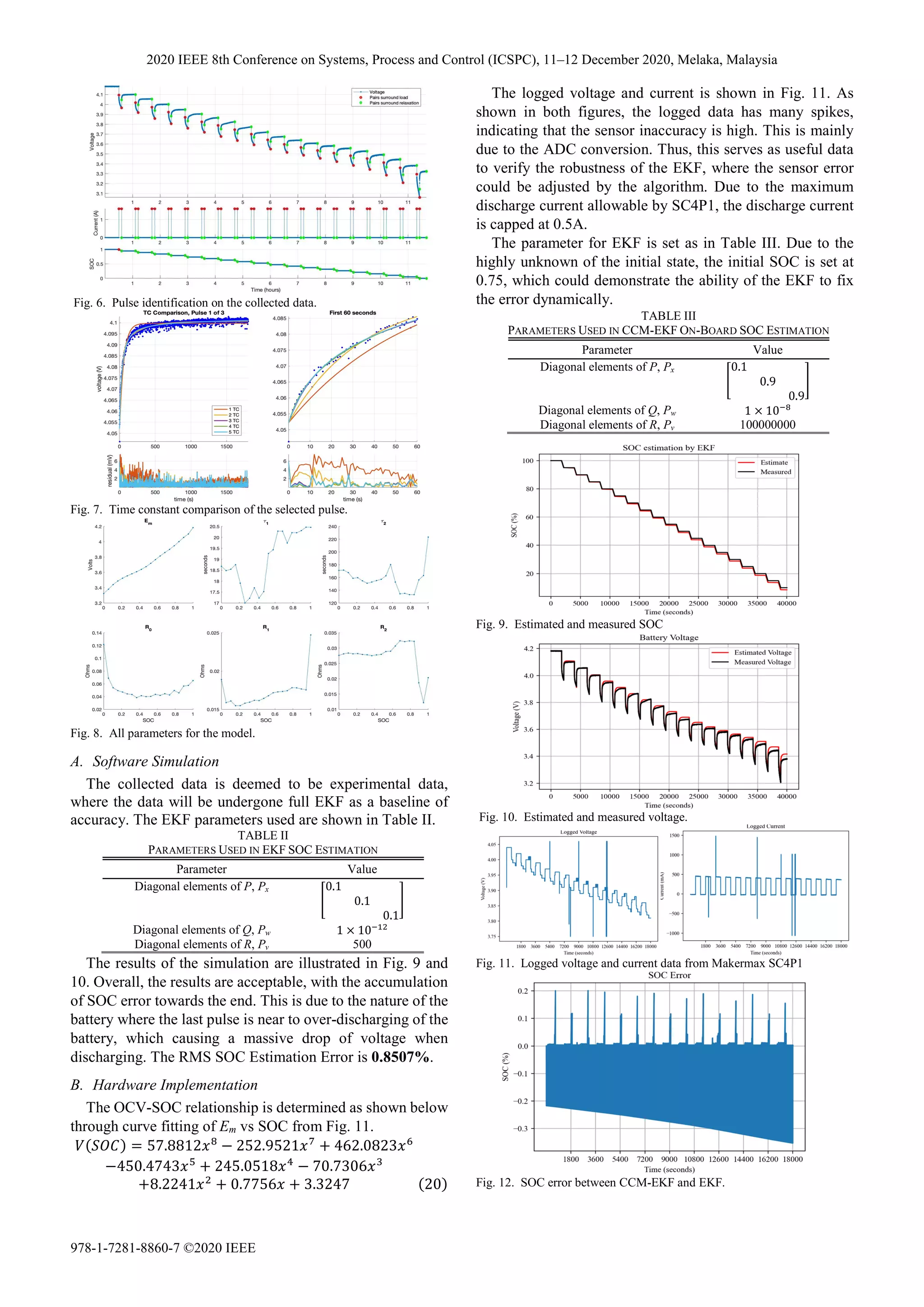
![The SOC estimation done by CCM-SOC is compared with
full EKF estimation. The SOC error is shown in Fig. 12. It is
observed that with such minor changes, it has brought the
possibility to done KF-based estimation on the memory-
limited microcontroller. The RMS SOC estimation error is
shown to be 0.0468% as compared to full EKF estimation.
V. CONCLUSION
This work has illustrated that the ability of low-memory
microcontroller can handle KF algorithm well, when doing
some minor changes to the algorithm, such as combining
them with lookup-based techniques to minimize the
consumption of memory in computing the estimation. This
work suggested the following possible improvements,
• The memory management on-chip. Currently, the code
was coded in Arduino environment, which is not an
optimized version of code, where there is a possibility of
memory overloading.
• Self EKF parameter selection and normalization.
• Multiple cells for on-chip estimation.
• More robust KF family algorithms can be used. This
work has demonstrated that EKF is possible even on
memory-limited chip, which made it possible for more
demanding KF, to deploy on high- memory chip.
ACKNOWLEDGEMENT
This work is partially supported by MIMOS Berhad.
REFERENCES
[1] H. Rahimi-Eichi, U. Ojha, F. Baronti, and M.-Y. Chow, "Battery
management system: An overview of its application in the smart
grid and electric vehicles," IEEE Industrial Electronics
Magazine, vol. 7, no. 2, pp. 4-16, 2013.
[2] C. Capasso and O. Veneri, "Experimental analysis on the
performance of lithium based batteries for road full electric and
hybrid vehicles," Applied Energy, vol. 136, pp. 921-930, 2014.
[3] B. Scrosati and J. Garche, "Lithium batteries: Status, prospects
and future," Journal of power sources, vol. 195, no. 9, pp. 2419-
2430, 2010.
[4] B. Bilgin et al., "Making the case for electrified transportation,"
IEEE Transactions on Transportation Electrification, vol. 1, no.
1, pp. 4-17, 2015.
[5] S. Castano, L. Gauchia, E. Voncila, and J. Sanz, "Dynamical
modeling procedure of a Li-ion battery pack suitable for real-time
applications," Energy Conversion and Management, vol. 92, pp.
396-405, 2015.
[6] Y. Diab, F. Auger, E. Schaeffer, and M. Wahbeh, "Estimating
lithium-ion battery state of charge and parameters using a
continuous-discrete extended Kalman filter," Energies, vol. 10,
no. 8, p. 1075, 2017.
[7] F. Asghar, M. Talha, S. H. Kim, and I.-H. Ra, "Simulation study
on battery state of charge estimation using Kalman Filter,"
Journal of Advanced Computational Intelligence Vol, vol. 20, no.
6, 2016.
[8] W.-Y. Chang, "The state of charge estimating methods for
battery: A review," ISRN Applied Mathematics, vol. 2013, 2013.
[9] S. Piller, M. Perrin, and A. Jossen, "Methods for state-of-charge
determination and their applications," Journal of power sources,
vol. 96, no. 1, pp. 113-120, 2001.
[10] Z. Cheng, J. Lv, Y. Liu, and Z. Yan, "Estimation of state of charge
for lithium-ion battery based on finite difference extended
Kalman filter," Journal of applied mathematics, vol. 2014, 2014.
[11] H. He, X. Zhang, R. Xiong, Y. Xu, and H. Guo, "Online model-
based estimation of state-of-charge and open-circuit voltage of
lithium-ion batteries in electric vehicles," Energy, vol. 39, no. 1,
pp. 310-318, 2012.
[12] D. G. Vutetakis and J. B. Timmons, "A comparison of lithium-
ion and lead-acid aircraft batteries," SAE Technical Paper, 0148-
7191, 2008.
[13] M. A. Kromer, "Electric powertrains: opportunities and
challenges in the US light-duty vehicle fleet," Massachusetts
Institute of Technology, 2007.
[14] L. Lu, X. Han, J. Li, J. Hua, and M. Ouyang, "A review on the
key issues for lithium-ion battery management in electric
vehicles," Journal of power sources, vol. 226, pp. 272-288, 2013.
[15] F. Feng, R. Lu, and C. Zhu, "A combined state of charge
estimation method for lithium-ion batteries used in a wide
ambient temperature range," Energies, vol. 7, no. 5, pp. 3004-
3032, 2014.
[16] S. C. Hageman, "Simple PSpice models let you simulate common
battery types," EDN, vol. 38, no. 22, pp. 117-&, 1993.
[17] J. Meng, G. Luo, M. Ricco, M. Swierczynski, D.-I. Stroe, and R.
Teodorescu, "Overview of lithium-ion battery modeling methods
for state-of-charge estimation in electrical vehicles," Applied
Sciences, vol. 8, no. 5, p. 659, 2018.
[18] H. He, R. Xiong, and J. Fan, "Evaluation of lithium-ion battery
equivalent circuit models for state of charge estimation by an
experimental approach," energies, vol. 4, no. 4, pp. 582-598,
2011.
[19] C. R. Gould, C. M. Bingham, D. A. Stone, and P. Bentley, "New
battery model and state-of-health determination through subspace
parameter estimation and state-observer techniques," IEEE
Transactions on Vehicular Technology, vol. 58, no. 8, pp. 3905-
3916, 2009.
[20] J. Feng, Y. He, and G. Wang, "Comparison study of equivalent
circuit model of Li-Ion battery for electrical vehicles," Res. J.
Appl. Sci. Eng. Technol, vol. 6, pp. 3756-3759, 2013.
[21] X. Liu, W. Li, and A. Zhou, "PNGV equivalent circuit model and
SOC estimation algorithm for lithium battery pack adopted in
AGV vehicle," Ieee Access, vol. 6, pp. 23639-23647, 2018.
[22] R. Xiong, H. He, F. Sun, and K. Zhao, "Evaluation on state of
charge estimation of batteries with adaptive extended Kalman
filter by experiment approach," IEEE Transactions on Vehicular
Technology, vol. 62, no. 1, pp. 108-117, 2012.
[23] S. Sepasi, R. Ghorbani, and B. Y. Liaw, "Improved extended
Kalman filter for state of charge estimation of battery pack,"
Journal of Power Sources, vol. 255, pp. 368-376, 2014.
[24] P. Shen, M. Ouyang, L. Lu, J. Li, and X. Feng, "The co-
estimation of state of charge, state of health, and state of function
for lithium-ion batteries in electric vehicles," IEEE Transactions
on vehicular technology, vol. 67, no. 1, pp. 92-103, 2017.
[25] R. E. Kalman, "A new approach to linear filtering and prediction
problems," 1960.
[26] A. Romero-Becerril and L. Alvarez-Icaza, "Comparison of
discretization methods applied to the single-particle model of
lithium-ion batteries," Journal of Power Sources, vol. 196, no.
23, pp. 10267-10279, 2011.
[27] P. Shrivastava, T. K. Soon, M. Y. I. B. Idris, and S. Mekhilef,
"Overview of model-based online state-of-charge estimation
using Kalman filter family for lithium-ion batteries," Renewable
and Sustainable Energy Reviews, vol. 113, p. 109233, 2019.
[28] X. Hu, F. Sun, and Y. Zou, "Comparison between two model-
based algorithms for Li-ion battery SOC estimation in electric
vehicles," Simulation Modelling Practice and Theory, vol. 34, pp.
1-11, 2013.
[29] C. Jiang, A. Taylor, C. Duan, and H. Bai, Extended Kalman Filter
based battery state of charge(SOC) estimation for electric
vehicles. 2013, pp. 1-5.
[30] H. Pan, Z. Lü, W. Lin, J. Li, and L. Chen, "State of charge
estimation of lithium-ion batteries using a grey extended Kalman
filter and a novel open-circuit voltage model," Energy, vol. 138,
pp. 764-775, 2017.
[31] J. Xie, J. Ma, and K. Bai, "State ‐ of ‐ charge estimators
considering temperature effect, hysteresis potential, and thermal
evolution for LiFePO4 batteries," International Journal of
Energy Research, vol. 42, no. 8, pp. 2710-2727, 2018.
[32] S. Yang, C. Deng, Y. Zhang, and Y. He, "State of charge
estimation for lithium-ion battery with a temperature-
compensated model," Energies, vol. 10, no. 10, p. 1560, 2017.
[33] M. Mastali, J. Vazquez-Arenas, R. Fraser, M. Fowler, S. Afshar,
and M. Stevens, "Battery state of the charge estimation using
Kalman filtering," Journal of Power Sources, vol. 239, pp. 294-
307, 2013.
[34] A. Narayan, "State and Parametric Estimation of Li-Ion Batteries
in Electrified Vehicles," ed, 2017.
2020 IEEE 8th Conference on Systems, Process and Control (ICSPC), 11–12 December 2020, Melaka, Malaysia
978-1-7281-8860-7 ©2020 IEEE](https://image.slidesharecdn.com/ahybridkalmanfilteringforstateofchargeestimationoflithium-ionbatteryusedinlow-poweredmicrocontroller-211207071555/75/A-hybrid-kalman-filtering-for-state-of-charge-estimation-of-lithium-ion-battery-used-in-low-powered-microcontroller-ccm-ekf-approach-6-2048.jpg)


![REAL_TIME_ESTIMATION_OF_SOC_AND_SOH[1].pptx](https://cdn.slidesharecdn.com/ss_thumbnails/realtimeestimationofsocandsoh1-241216082315-d72b8b6e-thumbnail.jpg?width=640&height=640&fit=bounds)