Concrete mixing plant terdiri dari beberapa merk, brand, produsen dan jenis
merk pencampur benton, pabrik pencampur beton, brand pencampur beton, jual, beli
Concrete mixing plant terdiri dari beberapa merk, brand, produsen dan jenis
merk pencampur benton, pabrik pencampur beton, brand pencampur beton, jual, beli
Con todas las virtudes de las punzonadoras Bsochert a CNC, esta versión es ideal para las empresas que recién se incorporan a la manufactura de piezas punzonadas o bien para empresas con producciones limitadas y de bajo volumen.
New Block Machine Catalogue From Lontto GroupKevin Lontto
Many types of Block Machine For sale from LONTTO.
Such as Concrete block machine, hollow block machine, automatic block machine, hydraulic block machine, clay brick machine and son.
More details: Please visit:www.block-machine.net
Brick & Block Making Machine From LONTTO GroupKevin Lontto
Block &Brick Making Machine From LONTTO, which is the professional manufacturer in China. And Lontto Have the 20+ years production experience for brick machine. And mnay types of block machine for sale. Such as: Concrete Block Machine, Clay brick machine, hydraulic block machine, mobile block machine and so on.
Punzonadora Boschert para barras de cobre y dobladora cnc controlada con soft...Grupo Idemet SA de CV
Punzonadora CNC, para barras de cobre. Solución completa para fabricar Barras de tableros de carga o distribución de energía. Es posible suministrar soluciones para Industria 4.0
Punzonadora de Torreta Boschert combicut Combinación plasma y punzonadoGrupo Idemet SA de CV
Catalogo de la punzonadora de torreta, Boschert combinada con plasma, de la Serie Boschert Combicut, la combinación incluye una fuente Plasma Marca Kjellberg con tecnología Hi- Focus que permite hacer corte fino desde espesores de 0.5 mm hasta 40 mm de espesor en acero al carbón.
Concrete mixing plant terdiri dari beberapa merk, brand, produsen dan jenis
merk pencampur benton, pabrik pencampur beton, brand pencampur beton, jual, beli
Concrete mixing plant terdiri dari beberapa merk, brand, produsen dan jenis
merk pencampur benton, pabrik pencampur beton, brand pencampur beton, jual, beli
Con todas las virtudes de las punzonadoras Bsochert a CNC, esta versión es ideal para las empresas que recién se incorporan a la manufactura de piezas punzonadas o bien para empresas con producciones limitadas y de bajo volumen.
New Block Machine Catalogue From Lontto GroupKevin Lontto
Many types of Block Machine For sale from LONTTO.
Such as Concrete block machine, hollow block machine, automatic block machine, hydraulic block machine, clay brick machine and son.
More details: Please visit:www.block-machine.net
Brick & Block Making Machine From LONTTO GroupKevin Lontto
Block &Brick Making Machine From LONTTO, which is the professional manufacturer in China. And Lontto Have the 20+ years production experience for brick machine. And mnay types of block machine for sale. Such as: Concrete Block Machine, Clay brick machine, hydraulic block machine, mobile block machine and so on.
Punzonadora Boschert para barras de cobre y dobladora cnc controlada con soft...Grupo Idemet SA de CV
Punzonadora CNC, para barras de cobre. Solución completa para fabricar Barras de tableros de carga o distribución de energía. Es posible suministrar soluciones para Industria 4.0
Punzonadora de Torreta Boschert combicut Combinación plasma y punzonadoGrupo Idemet SA de CV
Catalogo de la punzonadora de torreta, Boschert combinada con plasma, de la Serie Boschert Combicut, la combinación incluye una fuente Plasma Marca Kjellberg con tecnología Hi- Focus que permite hacer corte fino desde espesores de 0.5 mm hasta 40 mm de espesor en acero al carbón.
BULK-FLOW Straight Mass Flow Hopper brochureOswaldo Mino
Designed for unloading hard-to-flow products.
The Straight Mass Flow Hopper has been specifically designed to provide a solution for unloading of ISO 20', 30', 40' and 45’ marine containers, which are mounted on tilting chassis for gravity unloadings.
It is applied to the unloading of most bulk powder products of various industries such as these: carbonates, flours, cement, powdered milk, PVC, sugar, starch, and other hard-to-flow particles.
sales@bulk-flow.com | www.bulk-flow.com
Linear vibrating screen (as known as linear vibratory screen,linear vibrating screener)with advanced design can deal with a lot of application screening program.
Group Mechatronics is India's Largest CNC Machine Manufacturer. It has got three divisions- Prasad NC Machine Systems- Specializes in design and manufacturing of Large size CNC Turning and Machining Centers, Water Jet Germany- Specializes in design and Manufacturing of CNC Abrasive Water Jet Cutting Machines, and VHS Mechatronics- Specializes in Retrofitting and reconditioning of CNC Machines. This presentation gives more insight on the Group Mechatronics.
A presentation with exhaustive information about the general idea of formwork, the various types, the newest introductions and a comparative study between the conventional and modern-day formwork.
It also includes the study of causes of failure of formwork and the safety measures to be taken for preventing failure.
Formwork, lebih dikenal dengan nama bekesting/mal/cetakan, yang terbuat dari kayu, plywood, steel, yang berfungsi untuk membentuk beton segar sesuai dengan keinginan/desain.
Layaknya teknologi, formwork juga terus berkembang pesat, semakin simple namun tetap mempertahankan kekuatan.
Piletec Brochure - Piling Hammer BrochureLewis Ryan
Piletec Brochure with our full range of EMV, FSV, Croppers, Culvert Puller, Vibration Monitors and Augers.
Specifications of all equipment on offer to hire today.
View the UK's largest fleet of piling attachments.
KEY BAR CHUCK WITH QUICK-ACTION JAW CHANGE SYSTEM
The RÖHM key bar chucks with quick-acting jaw change system are used successfully in areas where extremely high clamping forces, high concentricity and reliable long-term repeatability are required. Thanks to the quick-acting jaw change system, the jaws can be quickly and easily turned, changed or offset over the entire clamping range within a few seconds.
Advantages
- Maximum clamping forces thanks to direct force transfer via the key bar system
- Maximum concentricity and axial run-out tolerance
- High user-friendliness thanks to quick-acting jaw change System
GEARED SCROLL CHUCKS
The RÖHM geared scroll chucks have proven themselves a thousand times over and have already been used successfully on lathes, rotary tables and dividing attachments for decades. The jaws can be adjusted over the entire clamping range in order to be able to very quickly clamp workpieces with a wide clamping diameter range without offsetting the jaws.
Adtantages
- Quick jaw adjustment over the entire clamping range
- Proven chuck with optimal price/performance ratio
- Protection of the machine spindle by means of splash-water edge
INDEPENDENT CHUCKS
Independent chucks from RÖHM are particularly successful and effective when force has top priority.
Due to the increased rigidity and optimal wear behavior, they are especially suitable for the Initial machining of irregular, regular and round workpieces and make high machining forces and a longer machine service life possible.
Advantages
- Safe and easy clamping of irregular, regular, as well as round workpieces by four
independently adjustable jaws
- Easy rough centering by means of concentric rings on the chuck body
- Direct force transfer through radially arranged threaded spindles
http://eshop.roehm.biz/roehm_de_en/online-shop/drehfutter-planscheiben.html
Sachpazis:Terzaghi Bearing Capacity Estimation in simple terms with Calculati...Dr.Costas Sachpazis
Terzaghi's soil bearing capacity theory, developed by Karl Terzaghi, is a fundamental principle in geotechnical engineering used to determine the bearing capacity of shallow foundations. This theory provides a method to calculate the ultimate bearing capacity of soil, which is the maximum load per unit area that the soil can support without undergoing shear failure. The Calculation HTML Code included.
Hierarchical Digital Twin of a Naval Power SystemKerry Sado
A hierarchical digital twin of a Naval DC power system has been developed and experimentally verified. Similar to other state-of-the-art digital twins, this technology creates a digital replica of the physical system executed in real-time or faster, which can modify hardware controls. However, its advantage stems from distributing computational efforts by utilizing a hierarchical structure composed of lower-level digital twin blocks and a higher-level system digital twin. Each digital twin block is associated with a physical subsystem of the hardware and communicates with a singular system digital twin, which creates a system-level response. By extracting information from each level of the hierarchy, power system controls of the hardware were reconfigured autonomously. This hierarchical digital twin development offers several advantages over other digital twins, particularly in the field of naval power systems. The hierarchical structure allows for greater computational efficiency and scalability while the ability to autonomously reconfigure hardware controls offers increased flexibility and responsiveness. The hierarchical decomposition and models utilized were well aligned with the physical twin, as indicated by the maximum deviations between the developed digital twin hierarchy and the hardware.
Hybrid optimization of pumped hydro system and solar- Engr. Abdul-Azeez.pdffxintegritypublishin
Advancements in technology unveil a myriad of electrical and electronic breakthroughs geared towards efficiently harnessing limited resources to meet human energy demands. The optimization of hybrid solar PV panels and pumped hydro energy supply systems plays a pivotal role in utilizing natural resources effectively. This initiative not only benefits humanity but also fosters environmental sustainability. The study investigated the design optimization of these hybrid systems, focusing on understanding solar radiation patterns, identifying geographical influences on solar radiation, formulating a mathematical model for system optimization, and determining the optimal configuration of PV panels and pumped hydro storage. Through a comparative analysis approach and eight weeks of data collection, the study addressed key research questions related to solar radiation patterns and optimal system design. The findings highlighted regions with heightened solar radiation levels, showcasing substantial potential for power generation and emphasizing the system's efficiency. Optimizing system design significantly boosted power generation, promoted renewable energy utilization, and enhanced energy storage capacity. The study underscored the benefits of optimizing hybrid solar PV panels and pumped hydro energy supply systems for sustainable energy usage. Optimizing the design of solar PV panels and pumped hydro energy supply systems as examined across diverse climatic conditions in a developing country, not only enhances power generation but also improves the integration of renewable energy sources and boosts energy storage capacities, particularly beneficial for less economically prosperous regions. Additionally, the study provides valuable insights for advancing energy research in economically viable areas. Recommendations included conducting site-specific assessments, utilizing advanced modeling tools, implementing regular maintenance protocols, and enhancing communication among system components.
Saudi Arabia stands as a titan in the global energy landscape, renowned for its abundant oil and gas resources. It's the largest exporter of petroleum and holds some of the world's most significant reserves. Let's delve into the top 10 oil and gas projects shaping Saudi Arabia's energy future in 2024.
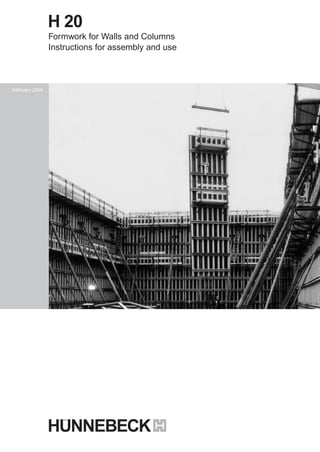
1. H 20
Formwork for Walls and Columns
Instructions for assembly and use
February 2004
1-1237.Aufbauanl.H20 D+GB 26.02.2004 10:20 Uhr Seite 2
2. 2
H20Contents
Page
1.0 Product features 3
H 20 timber beam 3
2.0 Overview 4
3.0 Components 5–12
4.0 List of walers 13
5.0 Ground plan 14
6.0 Assembly of element 15
7.0 Element connection 16
8.0 Corners 17–18
9.0 Stopend 19
10.0 T-Wall intersection 20
11.0 Height extension 21
12.0 Shaft formork 22
13.0 H20 Crane hook 23
14.0 HT-Walkway bracket 24
15.0 Strutting the formwork 25–26
16.0 Circular formwork 27
17.0 Column formwork 28–29
18.0 Technical data 30
19.0 Load tables 31–32
20.0 Execution of elements 33–34
21.0 Defined factors for calculation 35
Important notes
The following instructions for
erection and use include detailed
information on the handling and
proper application of the
products that are discribed and
depicted. All instructions
regarding technical operation and
function have to be observed
carefully.
Exceptional use requires a
separate design calculation.
With regard to safe and
technically correct use of our
products abroad, all relevant
safety rules, regulations and
safety instructions of national
institutes and/or local authorities
have to be followed.
Generally, only flawless material
must be used.
Damaged components have to
be sorted out. In case of repairs,
only original spare parts of the
Hünnebeck Company must be
used.
Combined use of our formwork
system with equip-
ment from other suppliers may
involve certain dangers and,
therefore, requires an additional
check up.
For reasons of further technical
development we emphatically
reserve the right to revise,
change or modify any of the
product's components at any
time without prior notice.
3. 3
H20
The basis of the wall formwork is
the H 20 timber beam. It is
produced in an electronically-
controlled production plant.
Wood quality and splicing is
continually checked, here.
The H 20 beam is sturdy, easy to
handle and at a weight of only
5.0 kg/m offers a high load-
bearing capacity at large
distances of walers.
The advantage: fewer ties.
Due to the project orientated
arrangement of beams
and tie positions, an optimum
adaptation to ground
1.0 Product features
plans and to the demanded
concrete surface will be
achieved.
The steel walers (clamped onto
the H 20 timber beam)
allow the formwork elements to
be assembled quickly
and simply. The assembly is
done as easily as the
disassembly. The advantage: no
problems with the
restructuring of wall formwork
units when a frequent
change of ground plans takes
place.
H 20 Timber beam
Beam dimensions [cm]
Beam end
Cross section
2.2
5 22.5
8
3.4
20
4
4
A
B
A
pb
perm. M = 5 kNm (bending moment)
perm. Q = 11 kN (shear force)
max B = 22 kN (support rection)
Flectural rigidity:
E • l = 500 kNm²
The H 20 beam is an economical
alternative to the
project-independent formwork
systems. It is definitely
the best when it comes to
complicated ground plans
and to numerous uniform-type
applications with the
same wall heights.
The H 20 timber beams are used
for wall, column and
slab formwork. They show high
stability at low weight.
The H20 timber beam has a general approval of the building
authorities under the registration number:
No. Z-9.1-299 and is designed for the following statical figures:
All safety regulations and safety
rules of local authorities have to
be considered for application.
Subject to change.
4. 4
H202.0 Overview
H20 Wall formwork
showing the typical arrangement of structural members.
HT-Walkway bracket
Wall strutSprag brace
Corner connector
Outer corner tensioning
H20-beam
Waler connector
Stop end
5. H20
5
Description Art. No.
Weight
kg/item
3.0 Components
H 20-beam 190
H 20-beam 245
H 20-beam 265
H 20-beam 290
H 20-beam 330
H 20-beam 360
H 20-beam 390
H 20-beam 450
H 20-beam 490
H 20-beam 590
H 20-beam 1190
Special lengths per metre run up to
max. length of 12.0 m (on request)
The H 20 beam is used for supporting and fastening
the shuttering skin. The spacing between the beams
in the wall element depends on the concrete
pressure and the selected shuttering skin.
9.5
12.3
13.2
14.5
16.5
18.0
19.5
22.5
24.5
29.5
59.5
5.0
581 760
581 770
581 781
581 792
581 807
581 818
581 829
581 830
581 840
581 851
582 319
581 862
Walers
22.5
27.9
33.4
38.9
44.3
49.7
55.0
60.7
66.2
503 871
503 882
503 893
503 908
503 919
503920
503 930
503 941
503 952
Walers
Waler 96
Waler 121
Waler 146
Waler 171
Waler 196
Waler 221
Waler 246
Waler 271
Waler 296
Special lengths are available on request.
Walers are joined with waler connectors to produce
a pressure- and tension resistant element
connection.
The element connections are thus tight flush and in
true alignment.
4.54.56 6 6 6 6 6 6
0.8568 048H 20 Timber beam clamp
It reliably connects the H 20 beam to the waler at
any required position. The rigid round bar stirrup
and the swivelling fingers grasp and tighten the
waler flanges to the beam (see page 15).
10
5
5
5 55.1
Spacer plate
5 / 0.6 x 4.9
11.3
6. H20Description Art. No.
Weight
kg/item
6
3.0 Components
22.5
27.8
33.3
38.6
43.9
49.3
54.7
60.1
65.4
505 907
505 918
505 930
505 951
505 962
505 973
505 984
506 007
506 018
Cam waler 96
Cam waler 121
Cam waler 146
Cam waler 171
Cam waler 196
Cam waler 221
Cam waler 246
Cam waler 271
Cam waler 296
The cam walers provide support and tying locations
in the elements.
The H 20 beams are attached to them with the
RU beam fastener.
4.5
6 6 6 6 6 6 6
10
5
5 55.1
3.9
Spacer plate
5 / 0.6 x 4.9
4.5
5
1.1568 703RU beam fastener
The beam fastener is required for circular formwork
when the H 20 beam is attached to cam walers
with intermediate arc templates (page page 27).
9.5
0.4506 614Three-hole plate
To be used with circular formwork. For attaching the
outer H 20 beam to the arc templates of the
shuttering element (page page 27).13
5 Ø 1.05
9.0505 311Corner connector 60 x 60
For forming inner corners of shafts. To be used with
joining wedge (see page 22).
7.4
13.0
505 274
505 296
Waler connector 100
Waler connector 165
For connecting formwork elements. To be attached
to the walers with the joining wedge (see page 16).100
60,5
60,5
11.0505 436Corner connector R 24 / H 20
For forming inner corners with length adjustments.
To be used with joining wedge (see page 17).
97.5
8
7. 0 H20
7
Description Art. No.
Weight
kg/item
3.0 Components
12.0
12.5
505 355
504 328
Hinged connector 70 x 70
Double hinged connector
For connecting skew arrangements of elements or
polygonal element conections in circular formwork.
Range 50° - 310° (see page 27).
68.5
68.5
8
4.2
1.5504 865Outer corner bearing
To be attached to the steel walers with the joining
wedge. Holds diagonal brace of the outer corner
(see page 18).
0.3504 497Wedge
For locking the beam fixing devices in place and
attaching wall struts or sprag braces. Also for
attaching connecttion beam KK 230 (BKS struts).
See page 16.
20
1.0
0.8
504 512
504 887
Beam fixing device
Beam fixing device for circular formwork.
To be used with infill panels and element
extensions. Provided with nail holes for attaching to
H 20 beams.
To be attached to the connectors with wedge
(Art. No. 504 497)* see page 16.
*) Order separately.
10
1.5505 388Tension strap
Component for stop-ends. To be secured in the
steel waler with the joining wedge. Can be used
with D+W tie rod (1.5 cm diam.) (see page 19).
8 15
4
0.9505 241Joining wedge
To be used with waler, corner and hinged
connectors, as well as outer corner bearings and
tension straps (see page 18).
24
8. H20Description Art. No.
Weight
kg/item
8
0.7504 291Corner stiffener R 24
Used as a diagonal stiffening between two H 20
beams for inner corners. Connection angles have
holes for nails measuring 5 mm in diametre (see page
17).
17
Brackets and aligning struts
14.1568 390HT Walkway bracket
Hot-dip galvanized bracket. Upper
U-profile equipped with a wooden lath for nailing
and with a squared tube for taking the separate
railing post (*
).
(*) To be provided additionally (see page 24).
110
4.5193 220TK-Railing post
Used together with HT Walkway bracket.
125
19.5
21.0
22.0
24.0
27.0
40.0
506 500
506 420
506 430
506 463
506 485
506 555
Wall struts with 2 hinge plates lacquered
Wall strut, Size 1 (170 - 240 cm)
Wall strut, Size 2 (220 - 290 cm)
Wall strut, Size 3 (270 - 340 cm)
Wall strut, Size 4 (320 - 390 cm)
Wall strut, Size 5 (420 - 490 cm)
Wall strut, Size 6 (530 - 590 cm)
For aligning and bracing formwork elements. To be
attached to the waler with the hinge plate. Needed
for this is the strut wedge strap (Art. No. 506 670)
and wedge Art. No. 504 497) (see page 25).
Ø 6
3.0 Components
9. 9
Description Art. No.
Weight
kg/item
H20
0.9506 670Strut wedge strap
For securing the hinge plates of wall struts and sprag
braces. Wedge (Art. No. 504 497) for fastening must
be ordered separately (see page 25).
16.0506 511Sprag brace, Size 1 lacquered
120 - 190 cm, for Sizes 1 + 2 wall struts
(with 1 hinge plate and 1 hinge bolt) see page 25.
18.0506 533Sprag brace, Size 2 lacquered
170 - 240 cm, for Sizes 3 + 4 wall struts
(with 1 hinge plate and 1 hinge bolt) see page 25.
To be secured to the lower waler with the hinge
plate. Attachment parts as for wall struts.
Ø 6
M20
12.5
3.0 Components
8.7582 320H 20 Crane hook
For setting upright, transporting and shifting
formwork elements (see page 23).
Max. allowable load per crane hook:
500 kg [5.0 kN]
Note: separate Operation Instructions (April, 1999).
Available (in German).
35
4.5
0.3
582 352
489 801
H 20 Extension butt strap
Bolt M20x80 with nut
Used for connecting individual beams when wall
elements are extended at height. (Extension butt
strap to be ordered 2 times, bolts M20 4 times).
Shown on page 21.
80
10. H20Description Art. No.
Weight
kg/item
10
3.0 Components
35.5
44.3
51.7
60.7
505 182
505 208
505 219
505 220
Walers for column formwork
Column waler 72 x 72
Column waler 89 x 89
Column waler 106 x 106
Column waler 123 x 123
For producing right-angled formwork halves
with various dimensions for column
shuttering. With welded-on squared bearing
supports.
Order bracing separately. See page 28.
1.9505 230Bearing bar for column waler
To be placed in the steel column waler
and to hold the 1.5 cm tie rod (see page 28).
15
0.3509 618Wing nut (forged)
To be used for wall ties and for bracing corners in
steel column walers.
Max. permitted load: 90 kN
See page 28.
5
1.0509 559Counter plate 12/12
In connection with the wing nut.
(Art.No. 509 618) see page 19.
12
1.1
1.4
1.9
2.5
437 660
024 387
020 481
020 470
Tie rod 75 (DW 15)
Tie rod 100
Tie rod 130
Tie rod 175
Max. permitted load: 90 kN
Not weldable.
Ø1,5
15.4
1.5
1.6
048 220
048 311
048 332
1 bundle of tubular sleeves, 25 pcs.
(each 200 cm long)
1 package of cones, 200 pcs.
1 package of plugs for sleeves, 500 pcs.
Sleeves with cones secure the distance
between two opposite shuttering elements.
11. 0 H20
11
Description Art. No.
Weight
kg/item
3.0 Components
1.2020 492Tie nut 85 (DW 15)
With large base plate and spherical nut.
Up to 10° incline is possible.
Max. permitted load: 90 kN.
TK Tension nut (DW 15)
For use in stopends.
Max. permitted load: 40 kN.
197332 0.7
10
1.3464 600Manto tie nut
Even when under a full tie load, can be easily
loosened with the ratchet, due to the special
sliding discs.
Max. permitted load: 90 kN.
13
13
22 2.4048 344Tie nut 230
With extremely large base plate and spherical nut.
Up to 10° incline is possible
Max. permitted load: 90 kN.
8
10.5
15
1.0408 780Manto ratchet
With the Manto ratchet (w.a.f. 36), tie nuts can be
tightened or loosened quickly, while saving strength
and materials. Do not extend the ratchet arm!
40
12. H20Description Art. No.
Weight
kg/item
12
3.0 Components
27,8529 540KK 230 Connection beam
For connecting BKS inclined struts to the H 20 wall
formwork. The vertical profile is connected to the
steel waler by means of the wedge strap, which is
welded on at the top, and the
wedge (Art. No. 504 497).
The lower waler transverse profile must be fixed to
the H 20 beam with 2 times
H 20 timber beam clamp (Art. No. 568 048).
These connection items must be ordered
separately. (see page 26).
76
31.5
75.0
100.0
504 659
504 660
504 670
Shaft corner 125
Shaft corner 300
Shaft corner 400
Clamping mechanism permits connection to the wall
element shuttering skin and eases stripping by
loosening the clamping joint following concreting.
(see page 22).
125
Inclined strut for extreme shuttering heights
Hinged end section
Hingeless end section
Intermediate section short 240 cm
Intermediate section long 370 cm
Bolt M16 x 60 with nut 4 pcs. per joint
Fit bolt M20 x 80 with nut 1 pc.
Combinable inclined struts (BKS struts) for
tension- and compression resistant strutting and
aligning of very high wall elements. To be
connected to the wall element with connection
beam KK 230.
Order separately.
See page 26.
489 102
489 775
489 113
489 124
489 786
489 801
36.2
29.0
44.0
63.0
0.2
0.4
Hinged end section
Intermediate section short
240 cm
Hingeless end section
Intermediate section long
370 cm
15. 15
H206.0 Assembly of elements
4 Attaching the shuttering skin
The shuttering skin is attached with nails, srew nails, or screws
(preferably Spax screws). With its width of 8 cm, the H 20 beam offers
a firm base for nailing or screwing.
2 Positioning the steel walers
on the assembly floor. Cams for cam walers or
traverses for steel walers are on the top.
3 Positioning the H 20 beam
in the statically required spacing.
Attaching of the beams with H 20 timber beam clamps
(see also note below).
Attaching the H 20 beam to the steel waler with the
H 20 timber beam clamp.
1 For basic assembly
of the H 20 elements, an assembly floor which is large enough for
the largest element must be provided. To assure the precise
postioning of the walers and beams, stop bars are nailed on. The
stop bars are to correspond to the waler spacing.
Preparation for assembly is the same for F-steel walers and for cam walers.
7 7
e e
(e = Beam spacing)
ee
H20Beam
H 20 Beam
Waler
shuttering skin
9
Element width(B)
5
3
7 Waler length
e
90°
H 20 timber beam clamp
2
16. 16
H20
1
2
3
4
Element connection
The connection of elements using waler connector 100 and four joining
wedges produces an aligned, compression- and tension-resistant
tightening of the wall elements.
Waler connector 100
Waler connector 165 is used to produce adjustment panels (max. 80 cm)
or to extend shuttering elements. As of 20 cm, additional tying is
necessary.
Beam fixing
device
Wedge
Place waler connector 100 with equal distances in the two adjacent
walers and secure it with Wedge 1 (first step). Then position Wedge 2
at a far distance (maximum possible spacing) and fasten it slightly.
Now insert Wedge 3 and tighten element joint. Fix Wedge 1 and
Wedge 3.
After this operation Wedge 4 and Wedge 2 must be tightly driven in.
Length adjustment
Using the beam fixing device and the wedge, the H 20 beam is
attached to the waler connector.
The beam fixing device has 0.6 cm diam. nail holes.
Beam fixing device
Wedge
max. 80 cm
Waler connector 165 Joining wedge
Waler connector 100
12 43
Waler connector 100
7.0 Element connection
17. 17
H208.0 Corners
Inner corner
The corner connector R 24 / H 20 makes it possible to construct an
inner corner by using standard elements.
Fastened to the waler with joining wedges.
Corner connector R24/H20
Note:
The shorter H 20 leg (17.5 cm) must point towards
the inner corner of the H 20 formwork.
97.5
8
17.5 8 19.5
Inner corner
Corner connector R24/H20 Art. No. 505 436 (1x)*
Joining wedge Art. No. 505 241 (4x)*
Corner stiffener Art. No. 504 291 (1x)*
*per each waler level
Standard element
Corner connector R24/H20
Side panel
Planed timber
Side panel
(fitted)
Planed timber
Beam fixing
device
Standard element
Wedge
Joining wedge
Planed timber
Corner stiffener
18. 18
H208.0 Corners
Outer corner
The standard outer corner is made from 2 standard elements.
The timber cleat prevents an offset of the elements during tightening.
The outer corner bearing can be fastened to the steel waler with the
joining wedge (Art. No 505 241).
Tightening the corner should be performed at an angle of 45° to the
waler.
Note:
Outer corner bearing application: min 40° to max. 50°.
Outer corner bearing
Joining wedge
Cleat
Standard element
Outer corner bearing
50°
40°
Tie rod Ø 1.5 cm
Wing nut Outer corner bearing
Joining wedge
Outer corner:
Outer corner bearing Art. No: 504 865 (2x)*
Joining wedge Art. No: 505 241 (2x)*
Tie rod 100, Ø 1.5 cm Art. No: 024 387 (1x)*
Wing nut Art. No: 509 618 (2x)*
*per each waler level
Outer corner bearing
Cleat
Wingnut
19. 19
H209.0 Stopend
The tension strap fits between the waler profiles of the
standard elements and is fixed in place with the joining wedge.
The compression loads from fresh concrete are absorbed by the tie
rods. Wing nut and counter plate allow for exact adjustment.
At least 2 additional H20 beams must be used for the stopend.
Stopend:
Tension strap Art. No. 505 388 (2x)*
Joining wedge Art. No. 505 241 (2x)*
Tie rod 75, Ø 1.5 cm Art. No. 437 660 (2x)*
Wing nut Art. No. 509 618 (2x)*
Counter plate 12/12 Art. No. 509 559 (2x)*
Beam fixing device Art. No. 504 512 (3x)*
Wedge Art. No. 504 497 (3x)*
Waler 171 Art. No. 503 908 (1x)*
*per each waler level
8 15
4
Tension strap
Tension strap Waler 171 Wing nut + Counter plate
Joining wedge
Tension strapJoining wedge
Joining wedge
Tension strapWaler Tie rod 75, Ø 1.5 cm
H20 Beam
Beam fixing device
+ Wedge
20. 20
H2010.0 T-Wall intersection
Constructing a T-wall intersection with standard elements and infill
field. For the infill field, use waler connector 165 (Art. No. 505 296)
(see page 16).
The inner corners are constructed in standard
design (standard element with side panel) see page 17.
Infillfield
Side panel
Joining wedge
Corner connector
Beam fixing device
Wegde
Corner connector
Waler connector 165
Beam fixing device
Wedge
Standard element
Standard element
Standard element
Standad element
Waler 165
21. 21
H20
The H 20 extension butt strap is used for extending elements.
It forms a connection between individual beams and produces a
tension- and compression resistant, rigid, aligned and offset- free
joint between beams or elements.
11.0 Height extension
H 20 Extension butt strap
H 20 Extension butt strap H 20 Beam
Extension butt strap + bolts
(build - in and tightened)
Bolt (4 x)
M20 x 80 with nut
Beam butt joint ready for use
80
The extension butt strap has to be installed on each H 20 beam joint
(exceptions are possible in individual cases, which must be carefully
examined and precisely described).
Both members must be ordered in the following number:
• 2 x H 20 Extension butt straps
• 4 x Bolts M20 x 80 with nuts
Bolt M20 x 80
with nut (4 x)
H 20 Extension butt strap
H 20 Extension butt strap
Bolt M20 x 80 with nut
H 20 Beam
22. 22
H2012.0 Shaft formwork
Shaft corner enable the inner corner of the formwork to be easily
stripped.
The wall elements are provided with a protruding cantilever of the
plywood supported by the shaft corner (see also detail below).
The rectangular connection of the walers is executed by means of the
corner connector 60 x 60 plus 4 joining wedges.
Corner connection 60 x 60
Shaft corner
min. 40 cm
10.5 cm
min.40cm
Shaft corner
Shaft corner 125
Shaft corner 300
Shaft corner 400
10.510.5
2 - 5 cm
23. 23
H20
The H 20 crane hook is put onto the H 20 beam end and then secured
by means of the integrated safety catch.
The lower pin of the safety catch must completely be inserted until it
stops. The permissible loading capacity per H 20 Crane hook is:
perm. F = 500 kg (5 kN)
H 20 crane hook
Safety catch
(tightly inserted)
Safety catch
(pulled out)
H 20 Crane hook
(funktions)
H 20 Wall element
< 60°
max. angle
of inclination:
13.0 Crane hook
H 20 crane hook
Operationinstructionsofthe
cranehookhavetobefollowed!
35
H 20 Crane hook
24. 24
H20
1. Attched to H 20 beam
(hole 2.2 cm dia)
The HT walkway bracket offers a working width of about 90 cm and is
produced as a ready-to-use scaffold bracket with a loose railing post
(TK railing post, Art. No. 193 220, has to be ordered additionally).
Plank dimensions and board thicknesses for guard rail should meet
the needs of the specific construction site situation.
Max. distance between walkway brackets: 1.50 m.
The walkway bracket is designed for Scaffolding Group 2, in line with
DIN 4420, Part 1, Edition 12/90.
2. Mounted onto the horizontal waler
(secured by pinning)
H 20 (horizontal)
3. Attched to a vertical waler
(secured by pinning)
14.0 HT-Walkway bracket
The HT walkway bracket is provided with a wooden lath for fastening
planks and with a safety pin for fixing the suspension head.
There are 3 different possibilities of attaching the
HT bracket to the formwork:
Safety pinSafety pin
Safety pin
TK-Railing post
HT-Walkway bracket
25. 25
H2015.0 Strutting the formwork
Wall struts with sprag braces
Used for aligning and supporting the formwork. They are tension- and
compression- resistant in picking up and diverting wind load. Wall strut
and sprag brace are supplied separately. The strut wedge strap and
wedge are used for fastening them to the waler.
Size
1
2
3
4
5
6
Art. No.
506 500
506 420
506 430
506 463
506 485
506 555
min. L
(m)
1.76
2.20
2.70
3.20
4.20
5.30
perm. F
(kN)
40
31
20
14
10
13
max. L
(m)
2.40
2.90
3.40
3.90
4.90
5.90
perm. F
(kN)
26
17
13
9
7
10
Wall strut
with double spindle and two hinge plate
Size
1
2
Art. No.
506 511
506 433
min. L
(m)
1.15
1.70
perm. F
(kN)
47
40
max. L
(m)
1.65
2.40
perm. F
(kN)
36
26
Sprag brace
with double spindle and one hinge plate
Ø 1.5
Ø 2.2
5.5
5.5
14
Strut wedge strap
Wedge
12.5
20
Hinge plate
Sprag brace
Wall strut
Hinge plate
Waler
Sprag brace
Strut wedge strap
Wedge
Note:
Vertical component
max.V = + 6.5 kN
26. 26
H2015.0 Strutting the formwork
Aligning strut BKS
The BKS aligning struts are suitable for tension- and compression-
resistant alignment of high or height- extended wall elements.
The BKS struts consist of individual components which can be joined
to make up the combinations shown below (Types 1 to 7).
Permitted loads are also shown in the table.
Technical data of the BKS aligning struts
End piece with
articulated plate
Elongated hole 1.8/3.8
18
12
33 18 26
Ø 3.5
Endpiecewithout
articulatedplate
108.7-178.7
Intermediatepiece370
Intermediatepiece240
α
Four bolts and nuts
M16 x 60 per joint
(quality of material 10.9)
Endpiecewith
articulatedplate115-185
KK 230 Connection beam BKS-Strut
BKS-Strut
Ø 2.5
Ø 2.1
Ø 2.5
Wedge
Art. No.
504 497
1 x ordered
separately
KK 230 Connection beam
BKS-Strut
Wedge
H20 Timber
beam clamp
Art. No.
568 048
2 x ordered
separately
H20 Timber beam clamp
Attention:
Vertical component
max.V = < 27.5 kN
Type
BKS 4
BKS 5
BKS 6
BKS 7
with art.
489 102
Length [cm]
perm. Load [kN]
min. max.
number of end pieces
fully extended without art.
489 775
number of interm. piece
long (370 cm)
489 124
short (240 cm)
489 113
703.7 - 843.7
833.7 - 973.7
963.7 - 1103.7
1073.7 - 1213.7
25
22
17.5
15
per 1 per 1
2
1
-
2
-
1
2
1
Note:
Vertical component
max.V = < 27.5 kN
27. 27
H2016.0 Circular formwork
H 20 elements which are in a polygonal arrangement (e.g. circular
shuttering) can be connected with one another using the hinged
connectors.
They are secured by inserting the joining wedges into the cam walers.
220
14930.5 5 30.55
11.6
3.68
11.6
3,68
196
Innerradius
11.6
3.98.9
234.8
Outerradius
225.4
234
17425
5 5
25
Section 1
Section 4
Section 2
Section 5
Section 3
Section 6
Radio
Example:
Sequence of construction for circular structure.
68.5
68.5
8
4.2
Hinged connector 70x70
Outer element
Inner element
Arc template
max. 15 cm
min. 5 cm
RU beam fastener
RU beam
fastener
Arc template (wood)
Three-hole plate
Waler
H 20 Beam
Arc templates:
29. 29
H2017.0 Column formwork
The column walers and H20 beams are
connected with H20 timber beam clamps.
100
100
130
130
100
100
90
C
87
5
245
265
290
330
360
390
450
490
590
h
45
45
30
30
30
30
30
30
30
A
130
130
100
100
100
100
90
90
90
B
130
130
130
D E
Column width (cm)
Number of beams per side
20
2
30
2
40 50
3 3
60 70
4 4
130
Table for column formwork
withamaximumconcretepressureof80kN/m²
Number of H 20 beams
A
B
C
D
E
with column waler
[cm]
rectangular cross-sectionssquare cross-sections
72 / 72
89 / 89
106 / 106
123 / 123
from to
20 / 20
20 / 37
20 / 54
20 / 71
72
(89,106,123)
72
(89, 106, 123)
72
(89,106,123)
H(cm)=Shutteringheight
72
(89, 106, 123)
20 / 36
20 / 53
20 / 70
20 / 87
from
20 / 20
37 / 37
54 / 54
71 / 71
to
36 / 36
53 / 53
70 / 70
87 / 87
Note:
21.0 mm plywood is subject to this column formwork.
(max. spacing of H 20 beams: e = 23 cm)
30. 30
H20
Fresh concrete pressure diagram
18.0 Technical data and load tables
General notes and explanations regarding the use of load tables
on page 31 and 32.
1. There are always three different figures of concrete pressure (40,
50 and 60 kN/m²) for the execution of H 20wall elements.
2. The wall heights of the elements are shown as static beam
systems with fixed arrangements of the walers (A, B, C, D, E,).
All dimensions given in the load tables are actual distances
between the walers.
The initial height at the bottom is always 40 cm.
3. The execution of the H 20 wall elements defined with element
numbers between 1 and 41 is based on shuttering skin (plywood)
with 18 mm thickness (Modulus of elasticity is assumed with
appr. 700 kN/cm²).
4. There are 2 different figures to be found for the spacing of H 20
beams, namely
a. determined by plywood 18 mm
b. determined by statical values of H 20
For the execution of elements, the smaller figures have
been taken into consideration.
5. The loading on the walers (A, B, C, etc.) are stated as
linear load [kN/m].
6. At the bottom of each load table, the relevant element numbers
(from 1 to 41) are shown. The element number depends on the
concrete pressure to be allowed and on the 9 different element
widths (B) which are based on the nine different F-waler
lengths (see page 31).
Notes and explanations with regard to the execution
of elements on page 33 and 34.
1. On page 33, all constructional details which are important
for the element design can be found (length of walers,
element widths, nos. of H 20 beams, exact spacing of
beams, etc.)
The fourth vertical column on page 24 contains the
element numbers between 1 and 41 which are also given in
the load tables. The arrangement of H 20 beams is based
on the details shown at the bottom on page 15 (item 4:
attaching the shuttering skin).
2. From page 34 the typical arrangements of wall ties can be
taken (A, C, C/2, C1, C2, D, E,) for each element number.
The tying schemes 1, 3 and 4 are fully symmetrical.
When using tying scheme 2, pay attension to wall elements
of the same length B facing each other bacause this tying
is not symmetrical.
3. Tie rods D+W 15 mm dia. have to be applied for all elements
(perm. load F = 90 kN per wall tie).
Diagram for determining the
fresh concrete pressure (pb)
on formwork in relation to the
rate of pour (vb) and
consistency "K" of fresh concrete
(acc. to DIN 18218).
Legend
K3 = KR = smooth concrete
K2 = KP = plastic concrete
K1 = KS = stiff concrete
compactingratio(acc.toWalz)
Assumptions
• Bulk density of fresh concrete 25 kN/m³
• Setting time of concrete = 5 hrs
• Impervious formwork
• Compaction with internal vibrator
• Temperature of fresh concrete + 15° C
1.0
1.04
1.10
1.18
1.20
1.30
1.40
1.41
rate of pour vbinm/h
0 0.5 1.0 1.5 2.0 2.5 3.0 3.5 4.0 4.5 5.0 5.5 6.0 6.5 7.0
hydrostaticheightofpressurehsinm
fluid concrete
17•vb+17
K3
14•v+18
K2
10•v+19
K1 5•v+21
Columns
Walls
pressureoffreshconcretepbinkN/m²
140
20
40
30
50
10
0
70
90
80
60
130
100
110
120
0
3
2
1
4
5
32. 32
H20
40 50 60 40 50 60 40 50 60 40 50 60
7.1 7.2 8.1 8.2
- A
-C
37
37
39
58.4
55.6
51
-
2
4
8
12
16
21
26
31
37
25
25
58.5
87.6
82.9
53
-
3
6
10
14
19
24
29
35
41
30
30
48.8
72.7
70.6
52.8
-
2
5
9
13
18
22
27
33
39
44
47
35.5
42
45.1
41.7
39.7
1
4
8
12
16
21
26
31
37
32
32
53.3
62.8
68.2
57.9
39.8
2
5
9
13
18
22
27
33
39
39
39
44.4
52.5
56.4
51.6
40.1
2
5
8
12
17
21
26
32
38
- A
1.201.4040
4.50
- B
1.50
-C
- A
- B
- A
- B
-C
9540
4.50
1.05
-C
- D
1.001.10
1.251.5540
4.90
1.70
- B
1.0040
4.90
1.001.25
- D
40 50 60 40
9.29.1
50 60
590
- A - A
-C
590
- B
1.301.3040
5.90
1.451.45
- D
- B
1.151.0040
5,90
1.101.15
- D
-C
-E
1.10
6060 5050 4040
490490450450
A
B
C
D
E
100
125
150
175
200
225
250
275
300
A
B
C
D
E
100
125
150
175
200
225
250
275
300
1.25
19.0 Load tables
21
21
63.8
104.7
53.6
-
-
3
-
-
-
-
-
-
-
-
25
25
52.9
89
53.1
-
-
3
6
10
14
19
24
29
35
41
27
27
53.5
76.9
44.6
-
-
3
5
9
13
18
23
28
34
40
33
33
42.9
61.5
43.7
-
-
2
5
8
12
17
22
27
32
38
22
22
64.5
89.4
44.1
-
-
3
6
10
-
-
-
-
-
-
37
51
34.9
39.7
42.1
31.2
-
2
4
8
12
16
21
26
31
37
35
42
43.5
50.1
50.2
31.1
-
2
5
8
12
17
21
26
32
38
30
35
52.1
60.6
54.5
30.8
-
2
5
9
13
18
22
27
33
39
31
31
42.4
70.8
50.8
-
-
2
5
9
13
17
22
27
33
39
37
40
35.9
39.9
41.4
46.8
-
2
4
8
12
16
21
26
31
37
30
36
53.8
60.1
60.2
48
-
2
5
9
13
18
22
27
33
39
35
39
44.9
49.6
52.5
48
-
2
5
8
12
17
21
26
32
38
elementwidthB[cm]
relevantElement-No.
for the execution
of wall elements depending on waler
length (element width B) and concrete
pressure.
(see also page 30 and 31)
freshconcretepressurepb[kN/m²]
wallelementsystem
Theheightsofthewallelementsshowninthestatical
systemsarebasedonstandardH20beamlengths
between2.45mand5.90m.
Elementwidths "B" from1.0mto3.0mcanbeused
instepsof25cm(seealsobelow).
heightofwallelement[cm]:
linear load on waler [kN/m] at
perm. beam spacing acc. to plywood 18 mm [cm]
perm. beam spacing acc. to H 20 values [cm]
33. 33
H2020.0 Execution of elements
(Part 1)
ArrangementandspacingofH20beams
96
121
146
171
196
221
246
271
296
3
4
5
4
5
6
4
5
6
7
5
6
7
8
5
6
7
8
9
6
7
8
9
10
7
8
9
10
11
7
8
9
10
11
12
8
9
10
11
12
13
ele-
ment
no.
F
[cm]
F
[cm]
designationanddesign
ofelements
H20spacingduetoelementwidth
B = F + M + F
M = n x e [cm]
(M=divisionmeasure,e=beamspacing)
100
125
150
175
200
225
250
275
300
M
7 7e e e e
FF
B
F
M
B
F
e e e e e e
F
M
B
F
B
[cm]
F=fixedmeasure(atbeginningandend)
waler
[cm]
(B=elementwidth)
elementsystem
9
9
9
9
9
9
9
9
9
9
9
9
9
9
(9)
9
9
9
9
9
9
9
9
9
9
9
9
9
9
9
9
9
9
9
9
9
9
9
9
9
9
2 x 41
3 x 27.3
4 x 20.5
3 x 35.7
4 x 26.8
5 x 21,4
3 x 44
4 x 33
5 x 26.4
6 x 22
4 x 39.3
5 x 31.4
6 x 26.2
7 x 22.4
4 x 45.5
5 x 36.4
6 x 30.3
7 x 26
8 x 22.8
5 x 41.4
6 x 34.5
7 x 29.6
8 x 25.9
9 x 23
6 x 38.7
7 x 33.1
8 x 29
9 x 25.8
10 x 23.2
6 x 42.8
7 x 36.7
8 x 32.1
9 x 28.6
10 x 25.7
11 x 23.4
7 x 40.3
8 x 35.3
9 x 31.3
10 x 28.2
11 x 25.6
12 x 23.5
1*
2
3
4
5
6
7*
8
9
10
11*
12
13
14
15*
16
17
18
19
20*
21
22
23
24
25*
26
27
28
29
30*
31
32
33
34
35
36*
37
38
39
40
41
nos.of
H20
pcs./
element
F = 9 cm
e=beamspacing
(centretocentreH20)
e ee e e e e e
9
9
9
9
9
9
9
9
9
9
9
9
9
9
9
9
9
9
9
9
9
9
9
9
9
9
9
9
9
9
9
9
9
9
9
9
9
9
9
9
9
*spacing allowed only with plywood 21 mm thick
35. 35
H20
Important features of the H 20 large-area formwork
21.0 Defined factors for calculations
5. Height extension
Wall elements can be extended at height by means of the H 20
extension butt straps. They are needed in pairs for individual beams.
Non-positive beam connections are assured in this way.
Advantage: Use of elements for varying wall heights.
6. Versatility
The H 20 large-area formwork can also be used in conjunction with
climbing brackets and rigid support frames (single-sided formwork) as
well as for columns, tunnels and other types of special formwork.
Advantage: Many-sided applications.
7. Additional components
All steel parts of the H 20 large-area formwork are hot-dip galvanized.
Advantage: Clean components without rust. Long life-expectancy of
all steel parts.
8. Approval of H 20 beam
The H 20 timber beam has a general approval of the Building
Supervisory Board. It is registered under the No. Z-9.1-299.
Production of H 20 beams is continuously controlled.
Advantage: High safety due to constant quality of the product.
C. Weights
H 20 timber beam: approx. 5.0kg/m
Steel waler: approx. 21.2 kg/m
Element: approx. 48.0 kg/m² without Ply
approx. 60.0 kg/m² with Ply
D. Time figures for erection / striking
Basic assembly: approx. 0.25 h/m²
Disassembly: approx. 0.15 h/m²
Erection and striking: approx. 0.30 - 0.50 h/m²
E. Transport volume of components
H 20 timber beams: approx. 0.022 m³/m
Steel walers: approx. 0.018 m³/m
Element without Ply: 0.24 - 0.31 m³/m² (*
Element with Ply: 0.33 - 0.38 m³/m² (*
*) dependent on method of loading
Defined factors for calculations
1. Basic assembly
The steel walers are fastened to the H 20 timber beams by means of
H 20 timber beam clamps. Fastening is possible at any section
of the steel walers.
Advantage: Quick and inevitable assembly and disassembly.
Safe connection.
2. Element connection
Adjacent elements are joined with waler connectors and joining
wedges.
Advantage: Connections are proof against tension and
compression, aligned and resistant against bending.
3. Adaptability
The variable adaptation of H 20 beams and steel walers makes the
flexible arrangement to any shape of ground plan possible. The 165
cm long waler connector allows length adjustments of up to 80 cm.
Advantage: Adequate adaptation to concrete pressure, disturbing
sections and adjustments.
4. Tying
Wall ties can be positioned accord. to statical requirements or as
required by the concrete structure itself. Page 34 shows
recommended tying schemes for standard elements.
Advantage: Disturbing sections can simply be solved.
A. Statical figures
H 20 timber beam Steel waler 2 x U-100
perm. Q = 11kN 92.2 kN
perm. M = 5 kNm 11.5 kNm
E • I = 500 kNm² 865 cm4
accord. to general approval by Spacing of ties
the Building. Supervisory Board (e) < 1.25 m
B. Dimensions
H 20 timber beam Steel waler 2 x U-100
H x W: 20 x 8 cm 10 x 15 cm
Lengths:1.90 m; 2.45 m; 2.65 m; 0.96 m up to 2.96 m
2.90 m; 3.30 m; 3.60 m; 3.90 m; in steps of 25 cm.
4.50 m; 4.90 m; 5.90 m; 11.90 m. Special lengths only
Special lengths up to 12.0 m on request
on request.
36. Hünnebeck GmbH
P. O. Box 104461, D-40853 Ratingen, Germany
Phone +49 (0) 2102/937-1, Fax +49 (0) 2102/37651
info@huennebeck.com, www.huennebeck.com
GB-02-04-1000-DDH
1-1237.Aufbauanl.H20 D+GB 26.02.2004 10:20 Uhr Seite 1