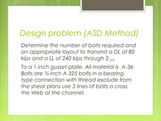
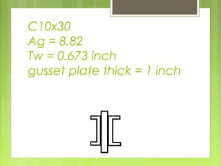
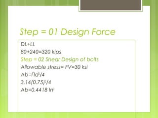
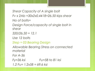
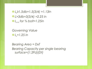
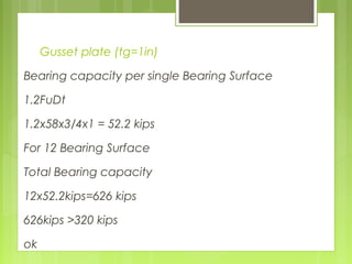
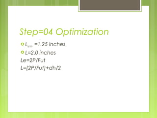
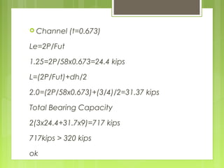
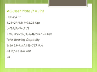
Steel Structure
Numerical
By
Engineer
Tayyeb Ullah Azhar
Design problem (ASD Method)
Determine the number of bolts required and
an appropriate layout to transmit a DL of 80
kips and a LL of 240 kips through 2c10*30
To a 1 inch gusset plate. All material is A-36
Bolts are ¾ inch A 325 bolts in a bearing
type connection with thread exclude from
the shear plans use 3 lines of bolts a cross
the Web of the channel.
C10x30
Ag = 8.82
Tw = 0.673 inch
gusset plate thick = 1 inch
Step = 01 Design Force
DL+LL
80+240=320 kips
Step = 02 Shear Design of bolts
Allowable stress= FV=30 ksi
Ab=Πd2
/4
3.14(0.75)2
/4
Ab=0.4418 In2
Shear Capacity of A single bolt
Fv x 2Ab =30x2x0.4418=26.50 kips shear
No of bolts=
Design Force/capacity of single bolt in
shear
320/26.50 = 12.1
Use 12 bolts
Step = 03 Bearing Design
Allowable Bearing Stress on connected
material
For A-36
Fy=36 ksi Fu=58 to 81 ksi
1.2 Fu= 1.2x58 = 69.6 ksi
 Le≥1.5db=1.5(3/4) =1.13in
 L>3db=3(3/4) =2.25 in
 Le min for ¾ bolt=1.25in
Governing Value
 Le=1.25 in
Bearing Area = DxT
Bearing Capacity per single bearing
surface=(1.2FU)(Dt)
Bearing Stress
Channel(tw=0.673)web
Bearing capacity per single bearing surface
(1.2Fu)(Dt)
1.2x58x3/4x0.673=35.13 kips
For 24 bearing surface
Total Bearing capacity
24x35.13 = 843 kips
843 > 320 kips
ok
Gusset plate (tg=1in)
Bearing capacity per single Bearing Surface
1.2FuDt
1.2x58x3/4x1 = 52.2 kips
For 12 Bearing Surface
Total Bearing capacity
12x52.2kips=626 kips
626kips >320 kips
ok
Step=04 Optimization
 Le min =1.25 inches
 L=2.0 inches
Le=2P/Fut
L=(2P/Fut)+dh/2
 Channel (t=0.673)
Le=2P/Fut
1.25=2P/58x0.673=24.4 kips
L=(2P/Fut)+dh/2
2.0=(2P/58x0.673)+(3/4)/2=31.37 kips
Total Bearing Capacity
2(3x24.4+31.7x9)=717 kips
717kips > 320 kips
ok
 Gusset Plate (t = 1in)
Le=2P/Fut
1.25=2P/58x1=36.25 kips
L=(2P/Fut)+dh/2
2.0=(2P/58x1)+(3/4)/2=47.13 kips
Total Bearing Capacity
3x36.35+9x47.13)=533 kips
533kips > 320 kips
ok

Design Problem (ASD Method)

  • 1.
  • 2.
    Design problem (ASDMethod) Determine the number of bolts required and an appropriate layout to transmit a DL of 80 kips and a LL of 240 kips through 2c10*30 To a 1 inch gusset plate. All material is A-36 Bolts are ¾ inch A 325 bolts in a bearing type connection with thread exclude from the shear plans use 3 lines of bolts a cross the Web of the channel.
  • 3.
    C10x30 Ag = 8.82 Tw= 0.673 inch gusset plate thick = 1 inch
  • 4.
    Step = 01Design Force DL+LL 80+240=320 kips Step = 02 Shear Design of bolts Allowable stress= FV=30 ksi Ab=Πd2 /4 3.14(0.75)2 /4 Ab=0.4418 In2
  • 5.
    Shear Capacity ofA single bolt Fv x 2Ab =30x2x0.4418=26.50 kips shear No of bolts= Design Force/capacity of single bolt in shear 320/26.50 = 12.1 Use 12 bolts Step = 03 Bearing Design Allowable Bearing Stress on connected material For A-36 Fy=36 ksi Fu=58 to 81 ksi 1.2 Fu= 1.2x58 = 69.6 ksi
  • 6.
     Le≥1.5db=1.5(3/4) =1.13in L>3db=3(3/4) =2.25 in  Le min for ¾ bolt=1.25in Governing Value  Le=1.25 in Bearing Area = DxT Bearing Capacity per single bearing surface=(1.2FU)(Dt)
  • 7.
    Bearing Stress Channel(tw=0.673)web Bearing capacityper single bearing surface (1.2Fu)(Dt) 1.2x58x3/4x0.673=35.13 kips For 24 bearing surface Total Bearing capacity 24x35.13 = 843 kips 843 > 320 kips ok
  • 8.
    Gusset plate (tg=1in) Bearingcapacity per single Bearing Surface 1.2FuDt 1.2x58x3/4x1 = 52.2 kips For 12 Bearing Surface Total Bearing capacity 12x52.2kips=626 kips 626kips >320 kips ok
  • 9.
    Step=04 Optimization  Lemin =1.25 inches  L=2.0 inches Le=2P/Fut L=(2P/Fut)+dh/2
  • 10.
     Channel (t=0.673) Le=2P/Fut 1.25=2P/58x0.673=24.4kips L=(2P/Fut)+dh/2 2.0=(2P/58x0.673)+(3/4)/2=31.37 kips Total Bearing Capacity 2(3x24.4+31.7x9)=717 kips 717kips > 320 kips ok
  • 11.
     Gusset Plate(t = 1in) Le=2P/Fut 1.25=2P/58x1=36.25 kips L=(2P/Fut)+dh/2 2.0=(2P/58x1)+(3/4)/2=47.13 kips Total Bearing Capacity 3x36.35+9x47.13)=533 kips 533kips > 320 kips ok