Downloaded 172 times

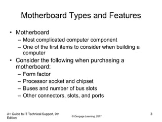
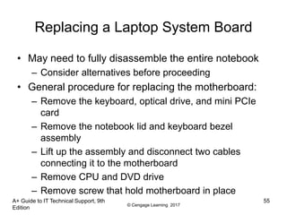

This document discusses motherboard types, features, and configuration. It describes common motherboard form factors like ATX, components like chipsets and sockets that determine processor compatibility, and buses that connect different components. It explains how to configure settings in BIOS or UEFI firmware, maintain a motherboard, and select an appropriate motherboard based on factors like the case and processor.