Download to read offline
![International Journal on Cybernetics & Informatics (IJCI) Vol. 4, No. 2, April 2015
DOI: 10.5121/ijci.2015.4215 157
A COMPARATIVE ANALYSIS AND APPLICATIONS OF
MULTI WAVELET TRANSFORM IN IMAGE
DENOISING
Smriti Bhatnagar1
and R.C.Jain2
1
Department of Electronics and Communication Engineering, Jaypee Institute Of
Information Technology, NOIDA, India
ABSTRACT
In the era of telemedicine a large amount of medical information is exchanged via electronic media mostly
in the form of medical images, to improve the accuracy and speed of diagnosis process. Medical Image
denoising has the basic importance in image analysis as these algorithm and procedures affects the efficacy
of medical diagnostic. In this paper focus is on Multi wavelets based Image denoising techniques, because
they provide the possibility of designing wavelets systems which are orthogonal, symmetric and compactly
supported, simultaneously. Performance of Discrete Multi Wavelet Transform and Discrete Wavelet
Transform based denoising methods are compared on the basis of PSNR.
KEYWORDS
Multiwaveletst; Wavelets; denoising.
1. INTRODUCTION
Recently, a lot of interest and research work is appearing in the development of denoising
algorithms for medical images in wavelet domain .Multi wavelets are the new paradigm added in
this domain. Multi wavelets present the advantages of simultaneous orthogonality, symmetry and
short support but at the cost of pre filtering and post filtering. Pre filtering is the process of
vectorizing the input before application of multi wavelets. Several methods are there to tackle this
problem [2, 3, 4, 5, 10]. The postfilter, on the other hand, maps the data from multiple channels
to one channel again.
In Multi wavelets case, more than one scaling and wavelet functions are used to represent a
signal. Multi wavelet decomposition can be implemented with filter banks as the case with scalar
wavelets but filter coefficients in this case are matrices instead of scalar values.
Instead of thresholding individual multi wavelet coefficients similar with scalar wavelets,
coefficient vectors are considered and thresholding operation is applied to the whole vector.
In this paper the multi wavelets based denoising technique is discussed and its performance is
compared on the basis of Peak Signal to Noise Ratio (PSNR) and Mean Square Error (MSE) with
scalar wavelet based denoising technique.
Section II gives mathematical preliminaries and notations associated with multi wavelet bases.
Discussion on chosen multi wavelets GHM and CL is also given in section II.](https://image.slidesharecdn.com/4215ijci15-150508060324-lva1-app6892/75/A-C-OMPARATIVE-A-NALYSIS-A-ND-A-PPLICATIONS-O-F-M-ULTI-W-AVELET-T-RANSFORM-I-N-I-MAGE-D-ENOISING-1-2048.jpg)
![International Journal on Cybernetics & Informatics (IJCI) Vol. 4, No. 2, April 2015
158
Section III comprises of pre filtering and post filtering techniques for implementation of
multiwavelet transform. Section IV characterizes the Multi wavelet Filter Banks. With the help of
filter banks discussed in section IV, in section V, denoising schemes with multi wavelets are
discussed and comparison of this scheme is done with other scalar wavelet techniques.
2. MATHEMATICAL PRELIMINARIES
Important mathematical concepts related with multi wavelets are discussed here.
2.1. Multiwavelets
Characterization of multi wavelets are done with multiple scaling functions and multiple wavelet
functions[1,2].
Denoting the scaling functions in the vector form as T
r tttt )](.........),(),([)( 110 −= φφφφ , )(tφ is
multiscaling function and T is transpose . )(tiφ is ith
scaling function. Similarly denoting the
wavelet functions in the vector form as T
r tttt )](.........),(),([)( 21 ψψψψ = , )(tψ is multiwavelet
function and T is transpose. )(tiψ is ith
wavelet function. The scaling space
)}2(),....,2({ 10 ktktspanV j
r
j
k
j −−= −φφ (1)
and the wavelet space
)}2(),....,2({ 10 ktktspanW j
r
j
k
j −−= −ψψ (2)
Dilation equation in traditional scalar wavelet is obtained from the nesting
condition 1+⊂ jj VV .Same is true for multi wavelets .The matrix dilation or refinement equation
for multi wavelets can be represented as
],2[2)( ktHt
k
k −= ∑ φφ (3)
and the wavelet equation as
],2[)( ktGt
k
k −=∑ ψψ (4)
Here the pair of filters Hk and Gk are low pass multi wavelet filter banks and high pass multi
wavelet filter banks respectively. These are rxr matrix filters instead of scalar filters in case of
wavelets. In general r = 2 is considered but it could be any value greater than 1. For r =2, these
filters will be 2 X 2 matrix filters operating on two input data stream. Filter coefficients are
matrices in the case of multi wavelets and provide more degree of freedom as compared to scalar
wavelets. For arbitrary chosen value of r, multi wavelets are known as of multiplicity r.](https://image.slidesharecdn.com/4215ijci15-150508060324-lva1-app6892/75/A-C-OMPARATIVE-A-NALYSIS-A-ND-A-PPLICATIONS-O-F-M-ULTI-W-AVELET-T-RANSFORM-I-N-I-MAGE-D-ENOISING-2-2048.jpg)
![International Journal on Cybernetics & Informatics (IJCI) Vol. 4, No. 2, April 2015
159
2.2. GHM and CL Multiwavelets
Alpert constructed the polynomial multi wavelets, and used them as basis for some operators.
After that Geronimo, Hardin and Massopust had done the construction of multi scaling function
for the first time with the help of fractal interpolation[2].
For multiplicity of 2 , eq (5) represents the relation of scaling functions φ1(t) and φ2(t) with low
pass filter coefficients and similarly eq (6) represents the relation of wavelet functions ψ1(t) and
ψ2(t) with high pass filter coefficients.
−Φ+−Φ+
−Φ+Φ=
=Φ
)32()22(
)12()2(
)(
)(
)(
32
10
2
1
tHtH
tHtH
t
t
t
ϕ
ϕ
(5)
−Φ+−Φ+
−Φ+Φ=
=Ψ
)32()22(
)12()2(
)(
)(
)(
32
10
2
1
tGtG
tGtG
t
t
t
ψ
ψ
(6)
Low pass filter coefficients H k’s and high pass filter coefficients Gk ’s for GHM are listed below
as eq (8) to eq (9)
−−
=
10/3210/1
5/245/3
0H ,
=
2/140/29
010/3
1H (7)
−
=
20/340/29
00
2H ,
−
=
040/2
00
3H
−−
=
20/340/2
5/2210/3
0G
−−
=
20/340/2
5/2210/3
1G (8)
−−
=
20/340/2
5/2210/3
2G
−−
=
20/340/2
5/2210/3
3G
GHM multi wavelet possess wonderful properties like its scaling functions are symmetric with
short support [0,1] and [0,2]. Scaling functions are orthogonal and multi wavelet functions are
symmetric/anti symmetric pair. This multi wavelet provides second order approximation[6].
Another interesting multi wavelet CL of multiplicity r posses [7] the low pass filter coefficients H
k’s and high pass filter coefficients Gk ’s listed below as eq(9) to eq(10).](https://image.slidesharecdn.com/4215ijci15-150508060324-lva1-app6892/75/A-C-OMPARATIVE-A-NALYSIS-A-ND-A-PPLICATIONS-O-F-M-ULTI-W-AVELET-T-RANSFORM-I-N-I-MAGE-D-ENOISING-3-2048.jpg)
![International Journal on Cybernetics & Informatics (IJCI) Vol. 4, No. 2, April 2015
160
−−
=
8/78/7
4/14/1
0H
=
4/10
02/1
1H
−−
−
=
8/78/7
4/14/1
2H (9)
−−
=
8/18/1
4/14/1
0G
=
20/70
02/1
1G
−
−
=
8/18/1
4/14/1
2G (10)
The CL multi wavelets also has some important properties like both of its scaling functions have
short support of [0, 2]. Scaling functions and wavelet functions are symmetric and anti symmetric
orthonormal pairs.
Such important properties cannot be fulfilled simultaneously in case of scalar wavelets. Filter
coefficients in multi wavelet cases are matrices and provide more degree of freedom in designing
and applications so the better performance is expected than scalar wavelets [8].
Graphical representation of scaling and wavelet functions for GHM is given in Figure 1.
Figure. 1 Scaling functions φ1(t) and φ2(t) and wavelet functions ψ1 (t) and ψ2 (t) for GHM Multi wavelet
Graphical representation of scaling and wavelet functions for CL is given in Figure 2.](https://image.slidesharecdn.com/4215ijci15-150508060324-lva1-app6892/75/A-C-OMPARATIVE-A-NALYSIS-A-ND-A-PPLICATIONS-O-F-M-ULTI-W-AVELET-T-RANSFORM-I-N-I-MAGE-D-ENOISING-4-2048.jpg)
![International Journal on Cybernetics & Informatics (IJCI) Vol. 4, No. 2, April 2015
161
3. PREFILTERING AND POSTFILTERING
Before applying multi wavelets, input data has to be pre processed or vectorized, which is known
as pre filtering or initialization of multi wavelets in literature. With the help of pre filters multiple
data streams are generated. Generally two types of pre filtering process are used, named as
repeated row pre filtering and critically sampled scheme[10]. Repeated row pre filtering is not
suited for data compression as it introduces redundancy. In critically sampled scheme, multiple
rows of data are generated by sampling the input data and distributing them to different rows [9].
Post filtering operation is mapping again from multiple streams to a single data stream or
reconstruction. Basically perfect reconstruction properties has to be satisfied by set of
preprocessing and post processing filters. Performance and design of multi wavelets depends a lot
on selection of these filters [12].
Figure.2.Scaling functions φ1(t)and φ2(t),Wavelet functions ψ1 (t) and ψ2 (t) for CL Multi
wavelet
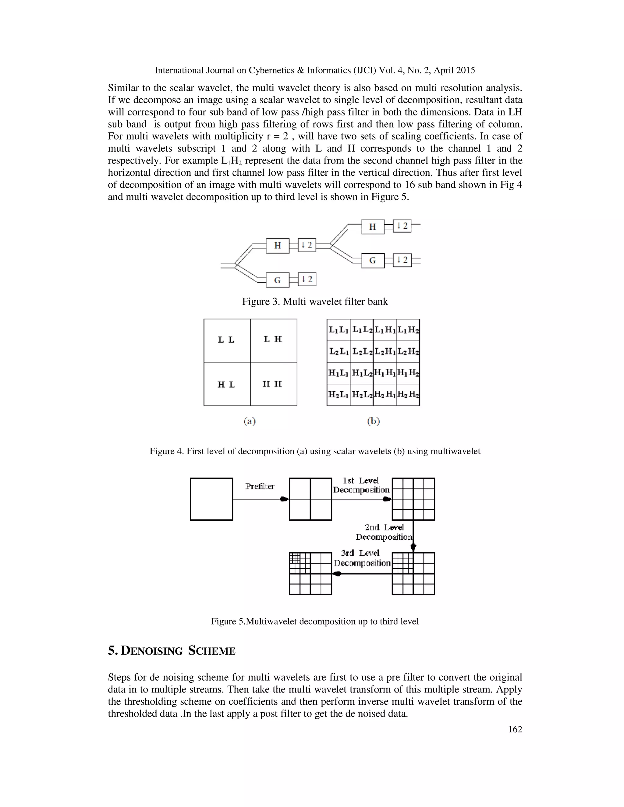
4. MULTIWAVELET FILTER BANKS
Multi wavelets of multiplicity ‘r’ require ‘r’ input streams to the multi wavelet filter banks. A
multi wavelet filter banks has taps that are rxr matrices. Coefficients for the low pass filter bank
Hk are given by four rxr matrices and the same is true for High pass filters Gk. Here coefficients
of high pass filter Gk cannot be obtained by flipping low pass filter coefficients as in it is done in
scalar wavelets [14]. It has to be designed separately. Finally r channel rxr matrix filter bank
operates on r input data streams and generate 2 r output streams which are then down sampled by
2. Every row of multifilters are a combination of r ordinary filters each operating on different data
stream. Figure 3 represents a multi wavelet filter bank[10].](https://image.slidesharecdn.com/4215ijci15-150508060324-lva1-app6892/75/A-C-OMPARATIVE-A-NALYSIS-A-ND-A-PPLICATIONS-O-F-M-ULTI-W-AVELET-T-RANSFORM-I-N-I-MAGE-D-ENOISING-5-2048.jpg)
![International Journal on Cybernetics & Informatics (IJCI) Vol. 4, No. 2, April 2015
163
Signal denoising techniques are based on the idea of thresholding the wavelet coefficients.
Wavelet coefficients having small absolute value are considered to have mostly noise and very
fine details of the signal. In contrast, the important information is represented by the coefficients
having large absolute value. Removing the small absolute value coefficients and then
reconstructing the signal should produce signal with lesser amount of noise. In case of multi
wavelets, thresholding whether hard or soft is applied on whole vector [11]. The thresholding of
the subband coefficients
are done by two ways(a) Hard theresholding function is defined as
)(.)( TxIxxF 〉= (11)
And (b) Soft threshold shrinks coefficients above the threshold in absolute value.
)())(sgn()( TxItxxxF 〉−= (12)
The only difference between the hard and the soft thresholding procedure is in the choice of the
nonlinear transform on the empirical wavelet coefficients [13]. Threshold T to be set to the
known noise level.
6. PARAMETERS FOR COMPARISON
6.1 Mean Square Error (MSE)
MSE, which for two m x n monochrome images x and y where one of the images is considered
noisy approximation of the other and is defined as in equation (13)
∑∑
−
=
−
=
−=
1
0
1
0
2
)],(),([
1 m
k
n
l
lkYlkX
mn
MSE (13)
6.2 Peak Signal to Noise Ratio (PSNR)
PSNR is the peak signal to noise ratio in decibels(dB). The PSNR is only meaningful for data
encoded in terms of bits per sample bits per pixel. For example an image with 8 bits per pixel
contains integers from 0-255. PSNR is given by the equation (14)
1)/MSE-(2log20PSNR B
10= (14)
Comparison is based on this parameter values for de noising schemes using different
wavelet/multi wavelets. Here B = No. of bits
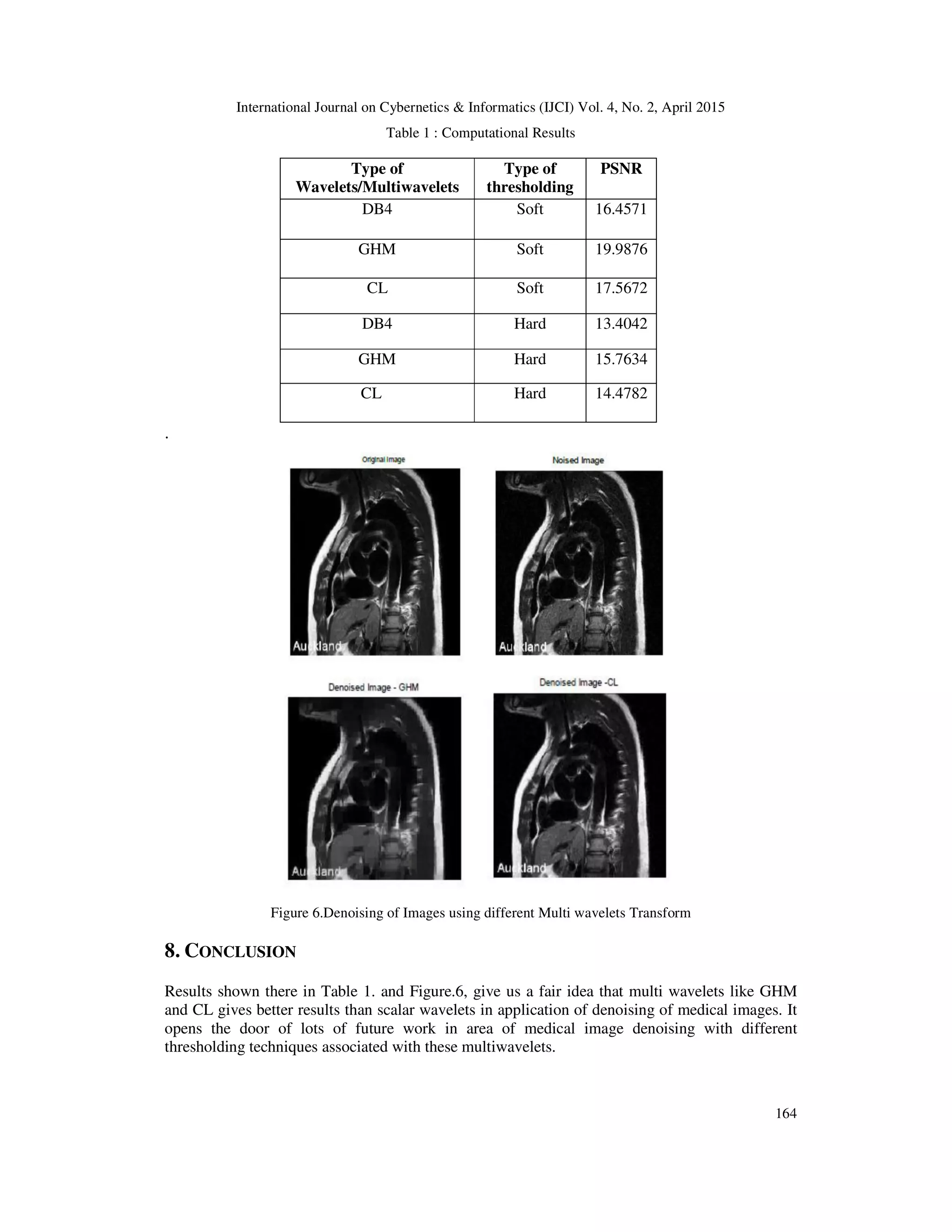
7. EXPERIMENTAL RESULTS
In experiment, test images used are de noised using GHM, CL and DB4. DB4 scalar wavelet is
used to compare the results of denoising of medical images with multi wavelets like GHM and
CL . Reason behind the selection of DB4 is its properties of orthogonality , 4 coefficients in the
dilation equation with 2 vanishing moments which are very similar to GHM multiwavelet.
Computatinal results are given in Table 1.](https://image.slidesharecdn.com/4215ijci15-150508060324-lva1-app6892/75/A-C-OMPARATIVE-A-NALYSIS-A-ND-A-PPLICATIONS-O-F-M-ULTI-W-AVELET-T-RANSFORM-I-N-I-MAGE-D-ENOISING-7-2048.jpg)
![International Journal on Cybernetics & Informatics (IJCI) Vol. 4, No. 2, April 2015
165
ACKNOWLEDGEMENTS
Medical images used here are taken form freely available medical images provided by Auckland
MRI Research Group.
REFERENCES
[1] T. N. T. Goodman and S. L. Lee, “Wavelets of multiplicity r,” Trans. Amer. Math. Soc., vol. 342, pp.
307-324, 1994.
[2] M. Cotronei, L. B. Montefusco, and L. Puccio, “Multiwavelet analysis and signal processing,” IEEE
Trans. Circuits Syst. II, vol. 45, no. 8, pp. 970-985, 1998.
[3] V. Strela, Multiwavelets: theory and applications, Ph.D. thesis, Massachusetts Institute of
Technology, Boston, Mass, USA,1996.
[4] D. P. Hardin and D. Roach, “Multiwavelet prefilters I: Orthogonal prefilters preserving
approximation order p ≤ 2,” IEEE Trans. Circuits Syst. II, vol. 45, no. 8, pp. 1106-1112,1998.
[5] V. Strela, P. Heller, G. Strang, P. Topiwala, and C. Heil, “The application of multiwavelet filter
banks to signal and image processing,” IEEE Trans. Image Processing, vol. 8, no. 4, pp. 548-
563, 1999.
[6] J. Geronimo, D. Hardin, and P. R. Massopust, “Fractal functions and wavelet expansions based
on several scaling functions,” J. Approx. Theory, vol. 78, no. 3, pp. 373-401, 1994.
[7] C. K. Chui and J. A. Lian, “A study of orthonormal multi-wavelets,” Cat report 351, Texas
A&M University, Texarkana,Tex, USA, 1995.
[8] J. Qumar and S. Gupta, “Performance Measure of Despeckling of SAR Image using
Multiwavelets ” NCC 2009, pp.357- 361, 2009.
[9] G. Strang and V. Strela, “Short wavelets and matrix dilation equations,” IEEE Trans. Signal
Processing, vol. 43, no. 1, pp.108-115, 1995.
[10] X. G. Xia, J. S. Geronimo, D. P. Hardin, and B. W. Suter, “Design of prefilters for discrete
multiwavelet transforms,” IEEETrans. Signal Processing, vol. 44, no. 1, pp. 25-35, 1996.
[11] T. R. Downie and B. W. Silverman, “The discrete multiple wavelet transform and thresholding
methods,” IEEE Trans. Signal Processing, vol.46, pp. 2558-2561, Sept. 1998.
[12] T. Nguyen and G. Strang, Wavelets and Filter Banks. Cambridge,MA: Wellesley-Cambridge,
1995.
[13] S.G.Chang , B.Yu, and M.Vitterli , “Adaptive Wavelet thresholding for image denoising and
compression” IEEE Transactions on Image Processing, vol. 9, no. 9, pp 1532-1546,Sept. 2000.
[14] M.B.Martin, and A.E.Bell “New Image Compression Techniques using multiwavelets and
multiwavelet packets” IEEE Transactions on Image Processing, vol. 10, no. 4, pp 500-510,April
2001.
AUTHORS
Smriti Bhatnagar is faculty at ECE Department, Jaypee Institute of Infor mation
Technology, NOIDA. She has done M.E., from MNIT, Allahabad. Her research interests
are System Design & Digital Signal Processing.
Dr.R.C.Jain is presently Professor & Head, ECE Department, Jaypee Institute of
Information Technology, NOIDA. He has done M. Eng., and Ph. D., Electrical
Engineering, from University of Alberta, Canada. His research area is Wireless
Communication Systems.](https://image.slidesharecdn.com/4215ijci15-150508060324-lva1-app6892/75/A-C-OMPARATIVE-A-NALYSIS-A-ND-A-PPLICATIONS-O-F-M-ULTI-W-AVELET-T-RANSFORM-I-N-I-MAGE-D-ENOISING-9-2048.jpg)

This paper analyzes multi-wavelet transform techniques for medical image denoising, highlighting their advantages over traditional scalar wavelet methods. The study compares the performance of discrete multi-wavelet denoising against scalar wavelet methods using peak signal-to-noise ratio (PSNR) and mean square error (MSE) metrics. Results indicate that multi-wavelet approaches like GHM and CL outperform scalar wavelets in effectively denoising medical images.


![1687 1499-2008-601346[1]](https://cdn.slidesharecdn.com/ss_thumbnails/1687-1499-2008-6013461-131222110733-phpapp02-thumbnail.jpg?width=640&height=640&fit=bounds)