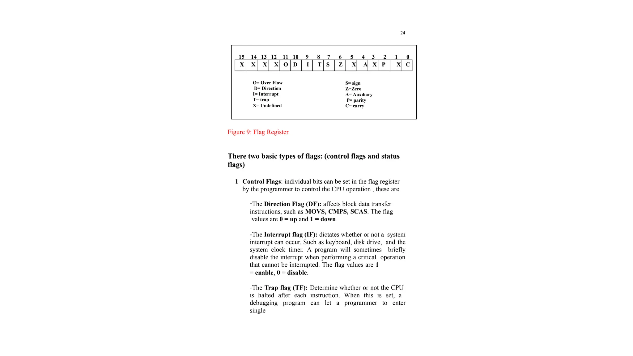
18
Segments and Addressing
Segments are special area defined in a program for containing the
code, the data, and the stack. Segment Offset within a program, all
memory locations within a segment are relative to the segment
starting address. The distance in bytes from the segment address to
another location within the segment is expressed as an offset (or
displacement).
To reference any memory location in a segment, the processor
combine the segment address in a segment register with the offset
value of that location, that is, its distance in byte from the start of
the segment.
Specifying addresses
To represent a segment address and its relative offset we use the
notation:
Segment: offset
Thus 020A:1BCD denotes offset 1BCDH from segment 020AH.
The actual address it refers to is obtained in the following way:
1 Add zero to the right hand side of the segment address.
2 Add to this the offset.
Hence the actual address referred to by 020A:1BCD is 03C6D.
19
Address Bus in the 8086 is 20 bits wide (20 lines) i.e. the processor
can access memory of size 220
or 1048576 bytes (1MB).
Instruction Pointer = 16 bit register which means the processor can
only address 0 – 216
(65535) bytes of memory. But we need to
write instructions in any of the 1MB of memory. This can be
solved by using memory segmentation., where each segment
register is 16-bit (this 16-bit is the high 16-bit of Address Bus (A4-
A19)) i.e. each of the segment registers represent the actual address
after shifting the address 4-bit to get 20 bits.
Registers
Registers are 8, 16, or 32-bit high speed storage locations directly
inside the CPU, designed to be accessed at much higher speed than
conventional memory.
FFFFF
Memory= 1 MB
00000
FF
0000
Only 64 KB can be used by IP
since it is 16-bit register
20
Figure 7: Intel 16-bit registers
The CPU has an internal data bus that is generally twice as wide as
its external data bus.
Data Registers: The general purpose registers, are used for
arithmetic and data movement. Each register can be addressed as
either 16-bit or 8 bit value. Example, AX register is a 16-bit
register, its upper 8-bit is called AH, and its lower 8-bit is called
AL. Bit 0 in AL corresponds to bit 0 in AX and bit 0 in AH
corresponds to bit 8 in AX. See Figure 8.
General Purpose
AX
BX
CX
DX
AH AL
BH BL
CH CL
DH DL
BP
SP
SI
DI
Index Reg.
Status & Control
Flag
IP
Segment Reg.
CS
SS
DS
ES
21
Figure 8: AX register
Instructions can address either 16-bit data register as AX, BX, CX,
and DX or 8-bit register as AL, AH, BL, BH, CL, CH, Dl, and
DH. If we move 126FH to AX then AL would immediately 6FH
and AH = 12H.
* Each general purpose register has special attributes:
1 AX (Accumulator): AX is the accumulator register because
it is favored by the CPU for arithmetic operations. Other
operations are also slightly more efficient when performed
using AX.
2 BX (Base): the BX register can hold the address of a
procedure or variable. Three other registers with this ability
are SI, DI and BP. The BX register can also perform
arithmetic and data movement.
3 CX (Counter): the CX register acts as a counter for
repeating or looping instructions. These instructions
automatically repeat and decrement CX.
AH AL
AX
15 0
7
0 7
0
22
4- DX (Data): the DX register has a special role in multiply and
divide operation. When multiplying for example DX hold
the high 16 bit of the product.
*Segment Registers: the CPU contain four segment registers,
used as base location for program instruction, and for the stack.
1 CS (Code Segment): The code segment register holds the
base location of all executable instructions (code) in a
program.
2 DS (Data Segment): the data segment register is the default
base location for variables. The CPU calculates their location
using the segment value in DS.
3 SS (Stack Segment): the stack segment register contain the
base location of the stack.
4 ES (Extra Segment): The extra segment register is an
additional base location for memory variables.
*Index registers: index registers contain the offset of data and
instructions. The term offset refers to the distance of a variable,
label, or instruction from its base segment. The index registers are:
1- BP (Base Pointer): the BP register contain an assumed
offset from the stack segment register, as does the stack
pointer. The base pointer register is often used by a
23
subroutine to locate variables that were passed on the stack
by a calling program.
2 SP (Stack Pointer): the stack pointer register contain the
offset of the top of the stack. The stack pointer and the stack
segment register combine to form the complete address of the
top of the stack.
3 SI (Source Index): This register takes its name from the
string movement instruction, in which the source string is
pointed to by the source index register.
4 DI (Destination Index): the DI register acts as the
destination for string movement instruction.
Status and Control register:
1 IP (Instruction Pointer): The instruction pointer register
always contain the offset of the next instruction to be
executed within the current code segment. The instruction
pointer and the code segment register combine to form the
complete address of the next instruction.
2 The Flag Register: is a special register with individual bit
positions assigned to show the status of the CPU or the result
of arithmetic operations. The Figure9 describe the 8086/8088
flags register:
24
Figure 9: Flag Register.
There two basic types of flags: (control flags and status
flags)
1 Control Flags: individual bits can be set in the flag register
by the programmer to control the CPU operation , these are
-The Direction Flag (DF): affects block data transfer
instructions, such as MOVS, CMPS, SCAS. The flag
values are 0 = up and 1 = down.
-The Interrupt flag (IF): dictates whether or not a system
interrupt can occur. Such as keyboard, disk drive, and the
system clock timer. A program will sometimes briefly
disable the interrupt when performing a critical operation
that cannot be interrupted. The flag values are 1
= enable, 0 = disable.
-The Trap flag (TF): Determine whether or not the CPU
is halted after each instruction. When this is set, a
debugging program can let a programmer to enter
single
X X X X O D I T S Z X A X P X C
15 14 13 12 11 10 9 8 7 6 5 4 3 2 1 0
O= Over Flow
D= Direction
I= Interrupt
T= trap
X= Undefined
S= sign
Z=Zero
A= Auxiliary
P= parity
C= carry

9_2019_01_06!10_26_04_PM.pptx what is register

  • 1.
    18 Segments and Addressing Segmentsare special area defined in a program for containing the code, the data, and the stack. Segment Offset within a program, all memory locations within a segment are relative to the segment starting address. The distance in bytes from the segment address to another location within the segment is expressed as an offset (or displacement). To reference any memory location in a segment, the processor combine the segment address in a segment register with the offset value of that location, that is, its distance in byte from the start of the segment. Specifying addresses To represent a segment address and its relative offset we use the notation: Segment: offset Thus 020A:1BCD denotes offset 1BCDH from segment 020AH. The actual address it refers to is obtained in the following way: 1 Add zero to the right hand side of the segment address. 2 Add to this the offset. Hence the actual address referred to by 020A:1BCD is 03C6D.
  • 2.
    19 Address Bus inthe 8086 is 20 bits wide (20 lines) i.e. the processor can access memory of size 220 or 1048576 bytes (1MB). Instruction Pointer = 16 bit register which means the processor can only address 0 – 216 (65535) bytes of memory. But we need to write instructions in any of the 1MB of memory. This can be solved by using memory segmentation., where each segment register is 16-bit (this 16-bit is the high 16-bit of Address Bus (A4- A19)) i.e. each of the segment registers represent the actual address after shifting the address 4-bit to get 20 bits. Registers Registers are 8, 16, or 32-bit high speed storage locations directly inside the CPU, designed to be accessed at much higher speed than conventional memory. FFFFF Memory= 1 MB 00000 FF 0000 Only 64 KB can be used by IP since it is 16-bit register
  • 3.
    20 Figure 7: Intel16-bit registers The CPU has an internal data bus that is generally twice as wide as its external data bus. Data Registers: The general purpose registers, are used for arithmetic and data movement. Each register can be addressed as either 16-bit or 8 bit value. Example, AX register is a 16-bit register, its upper 8-bit is called AH, and its lower 8-bit is called AL. Bit 0 in AL corresponds to bit 0 in AX and bit 0 in AH corresponds to bit 8 in AX. See Figure 8. General Purpose AX BX CX DX AH AL BH BL CH CL DH DL BP SP SI DI Index Reg. Status & Control Flag IP Segment Reg. CS SS DS ES
  • 4.
    21 Figure 8: AXregister Instructions can address either 16-bit data register as AX, BX, CX, and DX or 8-bit register as AL, AH, BL, BH, CL, CH, Dl, and DH. If we move 126FH to AX then AL would immediately 6FH and AH = 12H. * Each general purpose register has special attributes: 1 AX (Accumulator): AX is the accumulator register because it is favored by the CPU for arithmetic operations. Other operations are also slightly more efficient when performed using AX. 2 BX (Base): the BX register can hold the address of a procedure or variable. Three other registers with this ability are SI, DI and BP. The BX register can also perform arithmetic and data movement. 3 CX (Counter): the CX register acts as a counter for repeating or looping instructions. These instructions automatically repeat and decrement CX. AH AL AX 15 0 7 0 7 0
  • 5.
    22 4- DX (Data):the DX register has a special role in multiply and divide operation. When multiplying for example DX hold the high 16 bit of the product. *Segment Registers: the CPU contain four segment registers, used as base location for program instruction, and for the stack. 1 CS (Code Segment): The code segment register holds the base location of all executable instructions (code) in a program. 2 DS (Data Segment): the data segment register is the default base location for variables. The CPU calculates their location using the segment value in DS. 3 SS (Stack Segment): the stack segment register contain the base location of the stack. 4 ES (Extra Segment): The extra segment register is an additional base location for memory variables. *Index registers: index registers contain the offset of data and instructions. The term offset refers to the distance of a variable, label, or instruction from its base segment. The index registers are: 1- BP (Base Pointer): the BP register contain an assumed offset from the stack segment register, as does the stack pointer. The base pointer register is often used by a
  • 6.
    23 subroutine to locatevariables that were passed on the stack by a calling program. 2 SP (Stack Pointer): the stack pointer register contain the offset of the top of the stack. The stack pointer and the stack segment register combine to form the complete address of the top of the stack. 3 SI (Source Index): This register takes its name from the string movement instruction, in which the source string is pointed to by the source index register. 4 DI (Destination Index): the DI register acts as the destination for string movement instruction. Status and Control register: 1 IP (Instruction Pointer): The instruction pointer register always contain the offset of the next instruction to be executed within the current code segment. The instruction pointer and the code segment register combine to form the complete address of the next instruction. 2 The Flag Register: is a special register with individual bit positions assigned to show the status of the CPU or the result of arithmetic operations. The Figure9 describe the 8086/8088 flags register:
  • 7.
    24 Figure 9: FlagRegister. There two basic types of flags: (control flags and status flags) 1 Control Flags: individual bits can be set in the flag register by the programmer to control the CPU operation , these are -The Direction Flag (DF): affects block data transfer instructions, such as MOVS, CMPS, SCAS. The flag values are 0 = up and 1 = down. -The Interrupt flag (IF): dictates whether or not a system interrupt can occur. Such as keyboard, disk drive, and the system clock timer. A program will sometimes briefly disable the interrupt when performing a critical operation that cannot be interrupted. The flag values are 1 = enable, 0 = disable. -The Trap flag (TF): Determine whether or not the CPU is halted after each instruction. When this is set, a debugging program can let a programmer to enter single X X X X O D I T S Z X A X P X C 15 14 13 12 11 10 9 8 7 6 5 4 3 2 1 0 O= Over Flow D= Direction I= Interrupt T= trap X= Undefined S= sign Z=Zero A= Auxiliary P= parity C= carry