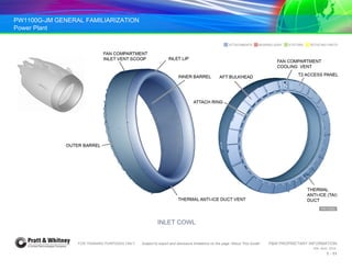
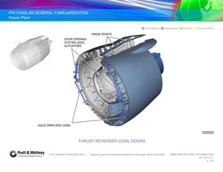
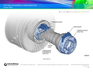
PW1100G-JM GENERAL FAMILIARIZATION
Power Plant
FOR TRAINING PURPOSES ONLY Subject to export and disclosure limitations on the page “About This Guide” P&W PROPRIETARY INFORMATION
934 AUG 2014
1 - 1
POWER PLANT
ATA 71
CHAPTER 1
FOR TRAINING PURPOSES ONLY Subject to export and disclosure limitations on the page “About This Guide” P&W PROPRIETARY INFORMATION
934 AUG 2014
1 - 1
PW1100G-JM GENERAL FAMILIARIZATION
Power Plant
FOR TRAINING PURPOSES ONLY Subject to export and disclosure limitations on the page “About This Guide” P&W PROPRIETARY INFORMATION
934 AUG 2014
1 - 2
PW1100G-JM GENERAL FAMILIARIZATION
Power Plant
FOR TRAINING PURPOSES ONLY Subject to export and disclosure limitations on the page “About This Guide” P&W PROPRIETARY INFORMATION
934 AUG 2014
1 - 3
OBJECTIVES
1. Identify the purpose of the power plant.
2. List the nacelle systems.
3. Identify the purpose of the Drainage System.
PW1100G-JM GENERAL FAMILIARIZATION
Power Plant
FOR TRAINING PURPOSES ONLY Subject to export and disclosure limitations on the page “About This Guide” P&W PROPRIETARY INFORMATION
934 AUG 2014
1 - 4
OVERVIEW
The PW1100G-JM turbofan engine powers the Airbus NEO (New
Engine Option) aircraft. It is an axial-flow, twin spool turbofan engine
with an ultra-high bypass ratio, low speed gear-driven fan. The
engine includes core-mounted Angle and Main gearboxes, and is
mounted on a pylon that extends below and forward of the wing
leading edge.
Also known as the power plant, the engine supplies propulsive
energy to the aircraft and supplies electrical power and hydraulic
pressure for aircraft systems. In addition it provides pressurized air
for the aircraft Environmental Control System (ECS) that includes
cabin pressurization, heating, and cooling.
The power plant includes the basic engine with its control
components, the nacelle, and the Engine Buildup Units (EBU). The
engine is controlled by the Full Authority Digital Electronic Control
(FADEC) system and is designed for safe and reliable operation.
Advantages of the PW1100G-JM Engine
Conventional gas turbine engines cannot perform as efficiently as
the PW1100G-JM. The low compressor and low turbine are
restricted to less than optimal operating speeds so that fan speed
can be maintained in a range most efficient for fan diameter.
The geared technology of the PW1100G-JM allows the fan and low rotor
to operate at their optimal speeds for peak efficiency. These
improvements in performance reduce fuel consumption, air pollution, and
noise. At the same time, operating costs and environmental impact are
drastically reduced.
PW1100G-JM GENERAL FAMILIARIZATION
Power Plant
FOR TRAINING PURPOSES ONLY Subject to export and disclosure limitations on the page “About This Guide” P&W PROPRIETARY INFORMATION
934 AUG 2014
1 - 5
Sample Naming Convention: A320 Family
PW Pratt & Whitney
1 Engine model 1000
1 Airbus airframe
33 Thrust in lbs x 1,000
G Geared Turbo Fan (GTF)
J Japanese Aero Engines Corporation (JAEC)
M Motoren-und-Turbinen-Union Aero Engines (MTU)
Aircraft and Engine
Specifications
PW1100G Designation
Thrust 24,000 – 33,000 lbs
Overall pressure ratio 47:1
Bypass ratio 12:1
Engine inlet diameter
Overall nacelle: 102 in. (259 cm)
Fan blade tip: 81 in. (205.7 cm)
Engine weight of
demountable power plant
7457 lb (3382 kg)
Aircraft models A319, A320, A321
Passenger capacity 124 – 235
AIRBUS NEO SPECIFICATIONS
PW1100G-JM GENERAL FAMILIARIZATION
Power Plant
FOR TRAINING PURPOSES ONLY Subject to export and disclosure limitations on the page “About This Guide” P&W PROPRIETARY INFORMATION
934 AUG 2014
1 - 6
PW1100G-JM GENERAL FAMILIARIZATION
Power Plant
FOR TRAINING PURPOSES ONLY Subject to export and disclosure limitations on the page “About This Guide” P&W PROPRIETARY INFORMATION
934 AUG 2014
1 - 7
BEARING ASSY STATORS ROTATING PARTS
ATTACHMENTS
ENGINE PROFILE
PW1100G-JM GENERAL FAMILIARIZATION
Power Plant
FOR TRAINING PURPOSES ONLY Subject to export and disclosure limitations on the page “About This Guide” P&W PROPRIETARY INFORMATION
934 AUG 2014
1 - 8
NACELLE SYSTEMS
Nacelle systems components are mounted to the engine and to the
pylon. They provide the engine with these capabilities:
• an aerodynamic and protective enclosure for engine-mounted
components
• collection and discharge of oil, fuel, and hydraulic fluid from
the engine and its components.
Systems and their components are listed in the table at right.
Nacelle System Components
Engine-mounted
nacelle components
• Inlet cowl
• Exhaust nozzle
• Exhaust plug
Pylon-mounted nacelle
components
• Fan cowl
• Thrust reverser
Engine mounting
• Front
• Rear
• Thrust link
PW1100G-JM GENERAL FAMILIARIZATION
Power Plant
FOR TRAINING PURPOSES ONLY Subject to export and disclosure limitations on the page “About This Guide” P&W PROPRIETARY INFORMATION
934 AUG 2014
1 - 9
BEARING ASSY STATORS ROTATING PARTS
ATTACHMENTS
COMPONENTS FOR NACELLE SYSTEMS
PW1100G-JM GENERAL FAMILIARIZATION
Power Plant
FOR TRAINING PURPOSES ONLY Subject to export and disclosure limitations on the page “About This Guide” P&W PROPRIETARY INFORMATION
934 AUG 2014
1 - 10
COMPONENTS
Inlet Cowl
Purpose:
The inlet cowl’s aerodynamic barrel smooths airflow, providing
uniform pressure as air reaches the fan.
The cowl’s outer skin provides even airflow across the engine
nacelle. The inner skin forms the engine inlet and acoustic
treatment.
Location:
The inlet cowl is secured to the engine fan case Flange A by the
aluminum inlet attach ring. The outer barrel is a two-piece assembly
extending from the inlet lip interface to the leading edge of the fan
cowl. The outer barrel has two splice joints located at 5:00 and 7:00.
Description:
The forward bulkhead and aft bulkhead provide impact protection
and structural support for the inlet assembly.
Lightning strike protection is provided by an expanded copper
screen layer impregnated into the outer barrel assembly.
A panel in the outer barrel provides access for maintenance of the
Thermal Anti-Ice (TAI) duct that supplies the inlet lip with hot air.
Anti-ice air exits the TAI vent located at 6:00 on the inlet lip.
Opening the right fan cowl on the aft bulkhead provides access to
the anti-ice supply line.
A second panel serves the T2 probe and the wiring harness and
sense line that are routed aft across the inner barrel to the aft
bulkhead mounted interface.
A small flush inlet vent scoop located on the inlet outer barrel
provides fan compartment cooling.
The inner barrel has gravity drainage holes embedded within the
core.
PW1100G-JM GENERAL FAMILIARIZATION
Power Plant
FOR TRAINING PURPOSES ONLY Subject to export and disclosure limitations on the page “About This Guide” P&W PROPRIETARY INFORMATION
934 AUG 2014
1 - 11
BEARING ASSY STATORS ROTATING PARTS
ATTACHMENTS
INLET COWL
PW1100G-JM GENERAL FAMILIARIZATION
Power Plant
FOR TRAINING PURPOSES ONLY Subject to export and disclosure limitations on the page “About This Guide” P&W PROPRIETARY INFORMATION
934 AUG 2014
1 - 12
COMPONENTS (Cont.)
Fan Cowl
Purpose:
The fan cowl provides aerodynamic smoothness and a protective
enclosure for the engine fan case and accessories. Fan cowl doors
provide maintenance access to components and systems below.
• Anti-ice temperature and pressure sensors
• Electronic Engine Control (EEC)
• Prognostics and Health Management Unit (PHMU)
• Pylon disconnects
• Ignition exciter box
• Thrust reverser torque box
• Thrust Reverser Actuation System (TRAS)
Location:
The fan cowl covers the engine fan cases and is positioned
between the inlet and reverser cowls.
Description:
Fan cowl doors are a one-piece structure. Two fan cowl axial
locators per door align the cowls as they close. A copper mesh is
embedded in the fan cowl laminate for lightning strike protection.
Cowl doors are manually opened, and held open with forward and
aft Hold Open Rods (HOR).
The fan cowl is secured to the pylon above the engine by pins
installed through the cowl door hinges and pylon fittings. The fan
cowls are also secured beneath the engine by three tension
latches. Visual indicators on the latch handles show when the
latches have not been properly secured.
An aerodynamic strake deflects airflow as required in certain
maneuvers related to aircraft performance. The strake is mounted
to the fan cowl outer surface on the inboard side.
A fan cowl vent provides overpressure protection in the event of a
burst anti-ice duct. Drain holes at the bottom of the fan cowls
provide fluid drainage.
Each door has three hoist provisions used for removal and
installation.
PW1100G-JM GENERAL FAMILIARIZATION
Power Plant
FOR TRAINING PURPOSES ONLY Subject to export and disclosure limitations on the page “About This Guide” P&W PROPRIETARY INFORMATION
934 AUG 2014
1 - 13
BEARING ASSY STATORS ROTATING PARTS
ATTACHMENTS
FAN COWL COMPONENTS (1 OF 2)
PW1100G-JM GENERAL FAMILIARIZATION
Power Plant
FOR TRAINING PURPOSES ONLY Subject to export and disclosure limitations on the page “About This Guide” P&W PROPRIETARY INFORMATION
934 AUG 2014
1 - 14
COMPONENTS
Fan Cowl
Description (Cont.)
A fan cowl assist side latch secures the right-hand side fan cowl half
to the inlet cowl. The side latch facilitates fan cowl closing by one
person only.
The Oil Tank Access Door (OTAD) provides quick access to the oil
tank, allowing oil service without opening the cowling. The OTAD is
hinged at the front edge and secured with two latches that provide
redundancy at the aft edge of the panel.
Each of three fan cowl door latches has a fan cowl door proximity
sensor to alert the ground crew to the fan cowls’ position. Each
sensor is able to detect whether the relative latch is locked in order
to avoid any fan cowl door loss in flight.
PW1100G-JM GENERAL FAMILIARIZATION
Power Plant
FOR TRAINING PURPOSES ONLY Subject to export and disclosure limitations on the page “About This Guide” P&W PROPRIETARY INFORMATION
934 AUG 2014
1 - 15
BEARING ASSY STATORS ROTATING PARTS
ATTACHMENTS
FAN COWL COMPONENTS (2 OF 2)
PW1100G-JM GENERAL FAMILIARIZATION
Power Plant
FOR TRAINING PURPOSES ONLY Subject to export and disclosure limitations on the page “About This Guide” P&W PROPRIETARY INFORMATION
934 AUG 2014
1 - 16
THRUST REVERSER COWL DOORS
Thrust reverser cowl doors are comprised of two halves that are
mechanically independent. The halves hinge at the pylon, latching
together along the bottom split line. They can be opened using the
Door Opening System (DOS) by means of a hydraulic hand pump.
Each door is equipped with a Hold Open Rod (HOR).
PW1100G-JM GENERAL FAMILIARIZATION
Power Plant
FOR TRAINING PURPOSES ONLY Subject to export and disclosure limitations on the page “About This Guide” P&W PROPRIETARY INFORMATION
934 AUG 2014
1 - 17
BEARING ASSY STATORS ROTATING PARTS
ATTACHMENTS
THRUST REVERSER COWL DOORS
PW1100G-JM GENERAL FAMILIARIZATION
Power Plant
FOR TRAINING PURPOSES ONLY Subject to export and disclosure limitations on the page “About This Guide” P&W PROPRIETARY INFORMATION
934 AUG 2014
1 - 18
ENGINE MOUNTING SYSTEM
The engine mounts transfer engine loads to the pylon.
Mount assemblies have four functions:
• support the weight of the engine
• transmit the thrust of the engine to the pylon
• make sure the engine does not turn around its axis
• hold lateral loads.
Two mount assemblies and one sub-assembly are located between
the engine and the pylon: the forward and aft mounts, and the thrust
links, respectively.
The forward mount assembly is connected at the top of the engine’s
Compressor Intermediate Case. The aft mount assembly is
connected at the top of the engine’s Turbine Exhaust Case.
The thrust link sub-assembly is connected to the Compressor
Intermediate Case at approximately 9:30 and at 2:30, and to the
forward mount through a balance beam.
PW1100G-JM GENERAL FAMILIARIZATION
Power Plant
FOR TRAINING PURPOSES ONLY Subject to export and disclosure limitations on the page “About This Guide” P&W PROPRIETARY INFORMATION
934 AUG 2014
1 - 19
BEARING ASSY STATORS ROTATING PARTS
ATTACHMENTS
MOUNTS
BEARING ASSY STATORS ROTATING PARTS
ATTACHMENTS
PW1100G-JM GENERAL FAMILIARIZATION
Power Plant
FOR TRAINING PURPOSES ONLY Subject to export and disclosure limitations on the page “About This Guide” P&W PROPRIETARY INFORMATION
934 AUG 2014
1 - 20
ENGINE BUILDUP UNIT (EBU) SYSTEM
Engine Drains
The Engine Drain System collects and discharges oil, fuel, and
hydraulic fluid from the engine and pylon, delivering residuals to the
lower bifurcation drain mast through dedicated drain tubes.
Drain components are located on the left and right sides, and at the
bottom of the engine.
Drain paths have gaps around the Latch Access Panel (LAP) and
eight drain holes in the lower bifurcation fixed/access panels. The
LAP has outlets that allow Main Gearbox, engine component and
pylon drain tubes to drain fluids overboard from the nacelle.
Related components from each of eight outlets are identified on the
pylon tube at the drain mast and at placards on the LAP.
Engine components that drain through the drain mast are listed
below.
• 2.5 bleed valve actuator
• HPC master and slave stator
vane actuators
• LPC stator vane actuator
• Integrated Drive Generator IDG
• Integrated Fuel Pump and
Control
IFPC
• Hydraulic Engine Driven Pump EDP
• Ecology collector tank
PW1100G-JM GENERAL FAMILIARIZATION
Power Plant
FOR TRAINING PURPOSES ONLY Subject to export and disclosure limitations on the page “About This Guide” P&W PROPRIETARY INFORMATION
934 AUG 2014
1 - 21
BEARING ASSY STATORS ROTATING PARTS
ATTACHMENTS
ENGINE DRAINS
PW1100G-JM GENERAL FAMILIARIZATION
Power Plant
FOR TRAINING PURPOSES ONLY Subject to export and disclosure limitations on the page “About This Guide” P&W PROPRIETARY INFORMATION
934 AUG 2014
1 - 22
PW1100G-JM GENERAL FAMILIARIZATION
Power Plant
FOR TRAINING PURPOSES ONLY Subject to export and disclosure limitations on the page “About This Guide” P&W PROPRIETARY INFORMATION
934 AUG 2014
1 - 23
ENGINE DRAINS

934 - 01_Power Plant.pdf

  • 1.
    PW1100G-JM GENERAL FAMILIARIZATION PowerPlant FOR TRAINING PURPOSES ONLY Subject to export and disclosure limitations on the page “About This Guide” P&W PROPRIETARY INFORMATION 934 AUG 2014 1 - 1 POWER PLANT ATA 71 CHAPTER 1 FOR TRAINING PURPOSES ONLY Subject to export and disclosure limitations on the page “About This Guide” P&W PROPRIETARY INFORMATION 934 AUG 2014 1 - 1
  • 2.
    PW1100G-JM GENERAL FAMILIARIZATION PowerPlant FOR TRAINING PURPOSES ONLY Subject to export and disclosure limitations on the page “About This Guide” P&W PROPRIETARY INFORMATION 934 AUG 2014 1 - 2
  • 3.
    PW1100G-JM GENERAL FAMILIARIZATION PowerPlant FOR TRAINING PURPOSES ONLY Subject to export and disclosure limitations on the page “About This Guide” P&W PROPRIETARY INFORMATION 934 AUG 2014 1 - 3 OBJECTIVES 1. Identify the purpose of the power plant. 2. List the nacelle systems. 3. Identify the purpose of the Drainage System.
  • 4.
    PW1100G-JM GENERAL FAMILIARIZATION PowerPlant FOR TRAINING PURPOSES ONLY Subject to export and disclosure limitations on the page “About This Guide” P&W PROPRIETARY INFORMATION 934 AUG 2014 1 - 4 OVERVIEW The PW1100G-JM turbofan engine powers the Airbus NEO (New Engine Option) aircraft. It is an axial-flow, twin spool turbofan engine with an ultra-high bypass ratio, low speed gear-driven fan. The engine includes core-mounted Angle and Main gearboxes, and is mounted on a pylon that extends below and forward of the wing leading edge. Also known as the power plant, the engine supplies propulsive energy to the aircraft and supplies electrical power and hydraulic pressure for aircraft systems. In addition it provides pressurized air for the aircraft Environmental Control System (ECS) that includes cabin pressurization, heating, and cooling. The power plant includes the basic engine with its control components, the nacelle, and the Engine Buildup Units (EBU). The engine is controlled by the Full Authority Digital Electronic Control (FADEC) system and is designed for safe and reliable operation. Advantages of the PW1100G-JM Engine Conventional gas turbine engines cannot perform as efficiently as the PW1100G-JM. The low compressor and low turbine are restricted to less than optimal operating speeds so that fan speed can be maintained in a range most efficient for fan diameter. The geared technology of the PW1100G-JM allows the fan and low rotor to operate at their optimal speeds for peak efficiency. These improvements in performance reduce fuel consumption, air pollution, and noise. At the same time, operating costs and environmental impact are drastically reduced.
  • 5.
    PW1100G-JM GENERAL FAMILIARIZATION PowerPlant FOR TRAINING PURPOSES ONLY Subject to export and disclosure limitations on the page “About This Guide” P&W PROPRIETARY INFORMATION 934 AUG 2014 1 - 5 Sample Naming Convention: A320 Family PW Pratt & Whitney 1 Engine model 1000 1 Airbus airframe 33 Thrust in lbs x 1,000 G Geared Turbo Fan (GTF) J Japanese Aero Engines Corporation (JAEC) M Motoren-und-Turbinen-Union Aero Engines (MTU) Aircraft and Engine Specifications PW1100G Designation Thrust 24,000 – 33,000 lbs Overall pressure ratio 47:1 Bypass ratio 12:1 Engine inlet diameter Overall nacelle: 102 in. (259 cm) Fan blade tip: 81 in. (205.7 cm) Engine weight of demountable power plant 7457 lb (3382 kg) Aircraft models A319, A320, A321 Passenger capacity 124 – 235 AIRBUS NEO SPECIFICATIONS
  • 6.
    PW1100G-JM GENERAL FAMILIARIZATION PowerPlant FOR TRAINING PURPOSES ONLY Subject to export and disclosure limitations on the page “About This Guide” P&W PROPRIETARY INFORMATION 934 AUG 2014 1 - 6
  • 7.
    PW1100G-JM GENERAL FAMILIARIZATION PowerPlant FOR TRAINING PURPOSES ONLY Subject to export and disclosure limitations on the page “About This Guide” P&W PROPRIETARY INFORMATION 934 AUG 2014 1 - 7 BEARING ASSY STATORS ROTATING PARTS ATTACHMENTS ENGINE PROFILE
  • 8.
    PW1100G-JM GENERAL FAMILIARIZATION PowerPlant FOR TRAINING PURPOSES ONLY Subject to export and disclosure limitations on the page “About This Guide” P&W PROPRIETARY INFORMATION 934 AUG 2014 1 - 8 NACELLE SYSTEMS Nacelle systems components are mounted to the engine and to the pylon. They provide the engine with these capabilities: • an aerodynamic and protective enclosure for engine-mounted components • collection and discharge of oil, fuel, and hydraulic fluid from the engine and its components. Systems and their components are listed in the table at right. Nacelle System Components Engine-mounted nacelle components • Inlet cowl • Exhaust nozzle • Exhaust plug Pylon-mounted nacelle components • Fan cowl • Thrust reverser Engine mounting • Front • Rear • Thrust link
  • 9.
    PW1100G-JM GENERAL FAMILIARIZATION PowerPlant FOR TRAINING PURPOSES ONLY Subject to export and disclosure limitations on the page “About This Guide” P&W PROPRIETARY INFORMATION 934 AUG 2014 1 - 9 BEARING ASSY STATORS ROTATING PARTS ATTACHMENTS COMPONENTS FOR NACELLE SYSTEMS
  • 10.
    PW1100G-JM GENERAL FAMILIARIZATION PowerPlant FOR TRAINING PURPOSES ONLY Subject to export and disclosure limitations on the page “About This Guide” P&W PROPRIETARY INFORMATION 934 AUG 2014 1 - 10 COMPONENTS Inlet Cowl Purpose: The inlet cowl’s aerodynamic barrel smooths airflow, providing uniform pressure as air reaches the fan. The cowl’s outer skin provides even airflow across the engine nacelle. The inner skin forms the engine inlet and acoustic treatment. Location: The inlet cowl is secured to the engine fan case Flange A by the aluminum inlet attach ring. The outer barrel is a two-piece assembly extending from the inlet lip interface to the leading edge of the fan cowl. The outer barrel has two splice joints located at 5:00 and 7:00. Description: The forward bulkhead and aft bulkhead provide impact protection and structural support for the inlet assembly. Lightning strike protection is provided by an expanded copper screen layer impregnated into the outer barrel assembly. A panel in the outer barrel provides access for maintenance of the Thermal Anti-Ice (TAI) duct that supplies the inlet lip with hot air. Anti-ice air exits the TAI vent located at 6:00 on the inlet lip. Opening the right fan cowl on the aft bulkhead provides access to the anti-ice supply line. A second panel serves the T2 probe and the wiring harness and sense line that are routed aft across the inner barrel to the aft bulkhead mounted interface. A small flush inlet vent scoop located on the inlet outer barrel provides fan compartment cooling. The inner barrel has gravity drainage holes embedded within the core.
  • 11.
    PW1100G-JM GENERAL FAMILIARIZATION PowerPlant FOR TRAINING PURPOSES ONLY Subject to export and disclosure limitations on the page “About This Guide” P&W PROPRIETARY INFORMATION 934 AUG 2014 1 - 11 BEARING ASSY STATORS ROTATING PARTS ATTACHMENTS INLET COWL
  • 12.
    PW1100G-JM GENERAL FAMILIARIZATION PowerPlant FOR TRAINING PURPOSES ONLY Subject to export and disclosure limitations on the page “About This Guide” P&W PROPRIETARY INFORMATION 934 AUG 2014 1 - 12 COMPONENTS (Cont.) Fan Cowl Purpose: The fan cowl provides aerodynamic smoothness and a protective enclosure for the engine fan case and accessories. Fan cowl doors provide maintenance access to components and systems below. • Anti-ice temperature and pressure sensors • Electronic Engine Control (EEC) • Prognostics and Health Management Unit (PHMU) • Pylon disconnects • Ignition exciter box • Thrust reverser torque box • Thrust Reverser Actuation System (TRAS) Location: The fan cowl covers the engine fan cases and is positioned between the inlet and reverser cowls. Description: Fan cowl doors are a one-piece structure. Two fan cowl axial locators per door align the cowls as they close. A copper mesh is embedded in the fan cowl laminate for lightning strike protection. Cowl doors are manually opened, and held open with forward and aft Hold Open Rods (HOR). The fan cowl is secured to the pylon above the engine by pins installed through the cowl door hinges and pylon fittings. The fan cowls are also secured beneath the engine by three tension latches. Visual indicators on the latch handles show when the latches have not been properly secured. An aerodynamic strake deflects airflow as required in certain maneuvers related to aircraft performance. The strake is mounted to the fan cowl outer surface on the inboard side. A fan cowl vent provides overpressure protection in the event of a burst anti-ice duct. Drain holes at the bottom of the fan cowls provide fluid drainage. Each door has three hoist provisions used for removal and installation.
  • 13.
    PW1100G-JM GENERAL FAMILIARIZATION PowerPlant FOR TRAINING PURPOSES ONLY Subject to export and disclosure limitations on the page “About This Guide” P&W PROPRIETARY INFORMATION 934 AUG 2014 1 - 13 BEARING ASSY STATORS ROTATING PARTS ATTACHMENTS FAN COWL COMPONENTS (1 OF 2)
  • 14.
    PW1100G-JM GENERAL FAMILIARIZATION PowerPlant FOR TRAINING PURPOSES ONLY Subject to export and disclosure limitations on the page “About This Guide” P&W PROPRIETARY INFORMATION 934 AUG 2014 1 - 14 COMPONENTS Fan Cowl Description (Cont.) A fan cowl assist side latch secures the right-hand side fan cowl half to the inlet cowl. The side latch facilitates fan cowl closing by one person only. The Oil Tank Access Door (OTAD) provides quick access to the oil tank, allowing oil service without opening the cowling. The OTAD is hinged at the front edge and secured with two latches that provide redundancy at the aft edge of the panel. Each of three fan cowl door latches has a fan cowl door proximity sensor to alert the ground crew to the fan cowls’ position. Each sensor is able to detect whether the relative latch is locked in order to avoid any fan cowl door loss in flight.
  • 15.
    PW1100G-JM GENERAL FAMILIARIZATION PowerPlant FOR TRAINING PURPOSES ONLY Subject to export and disclosure limitations on the page “About This Guide” P&W PROPRIETARY INFORMATION 934 AUG 2014 1 - 15 BEARING ASSY STATORS ROTATING PARTS ATTACHMENTS FAN COWL COMPONENTS (2 OF 2)
  • 16.
    PW1100G-JM GENERAL FAMILIARIZATION PowerPlant FOR TRAINING PURPOSES ONLY Subject to export and disclosure limitations on the page “About This Guide” P&W PROPRIETARY INFORMATION 934 AUG 2014 1 - 16 THRUST REVERSER COWL DOORS Thrust reverser cowl doors are comprised of two halves that are mechanically independent. The halves hinge at the pylon, latching together along the bottom split line. They can be opened using the Door Opening System (DOS) by means of a hydraulic hand pump. Each door is equipped with a Hold Open Rod (HOR).
  • 17.
    PW1100G-JM GENERAL FAMILIARIZATION PowerPlant FOR TRAINING PURPOSES ONLY Subject to export and disclosure limitations on the page “About This Guide” P&W PROPRIETARY INFORMATION 934 AUG 2014 1 - 17 BEARING ASSY STATORS ROTATING PARTS ATTACHMENTS THRUST REVERSER COWL DOORS
  • 18.
    PW1100G-JM GENERAL FAMILIARIZATION PowerPlant FOR TRAINING PURPOSES ONLY Subject to export and disclosure limitations on the page “About This Guide” P&W PROPRIETARY INFORMATION 934 AUG 2014 1 - 18 ENGINE MOUNTING SYSTEM The engine mounts transfer engine loads to the pylon. Mount assemblies have four functions: • support the weight of the engine • transmit the thrust of the engine to the pylon • make sure the engine does not turn around its axis • hold lateral loads. Two mount assemblies and one sub-assembly are located between the engine and the pylon: the forward and aft mounts, and the thrust links, respectively. The forward mount assembly is connected at the top of the engine’s Compressor Intermediate Case. The aft mount assembly is connected at the top of the engine’s Turbine Exhaust Case. The thrust link sub-assembly is connected to the Compressor Intermediate Case at approximately 9:30 and at 2:30, and to the forward mount through a balance beam.
  • 19.
    PW1100G-JM GENERAL FAMILIARIZATION PowerPlant FOR TRAINING PURPOSES ONLY Subject to export and disclosure limitations on the page “About This Guide” P&W PROPRIETARY INFORMATION 934 AUG 2014 1 - 19 BEARING ASSY STATORS ROTATING PARTS ATTACHMENTS MOUNTS BEARING ASSY STATORS ROTATING PARTS ATTACHMENTS
  • 20.
    PW1100G-JM GENERAL FAMILIARIZATION PowerPlant FOR TRAINING PURPOSES ONLY Subject to export and disclosure limitations on the page “About This Guide” P&W PROPRIETARY INFORMATION 934 AUG 2014 1 - 20 ENGINE BUILDUP UNIT (EBU) SYSTEM Engine Drains The Engine Drain System collects and discharges oil, fuel, and hydraulic fluid from the engine and pylon, delivering residuals to the lower bifurcation drain mast through dedicated drain tubes. Drain components are located on the left and right sides, and at the bottom of the engine. Drain paths have gaps around the Latch Access Panel (LAP) and eight drain holes in the lower bifurcation fixed/access panels. The LAP has outlets that allow Main Gearbox, engine component and pylon drain tubes to drain fluids overboard from the nacelle. Related components from each of eight outlets are identified on the pylon tube at the drain mast and at placards on the LAP. Engine components that drain through the drain mast are listed below. • 2.5 bleed valve actuator • HPC master and slave stator vane actuators • LPC stator vane actuator • Integrated Drive Generator IDG • Integrated Fuel Pump and Control IFPC • Hydraulic Engine Driven Pump EDP • Ecology collector tank
  • 21.
    PW1100G-JM GENERAL FAMILIARIZATION PowerPlant FOR TRAINING PURPOSES ONLY Subject to export and disclosure limitations on the page “About This Guide” P&W PROPRIETARY INFORMATION 934 AUG 2014 1 - 21 BEARING ASSY STATORS ROTATING PARTS ATTACHMENTS ENGINE DRAINS
  • 22.
    PW1100G-JM GENERAL FAMILIARIZATION PowerPlant FOR TRAINING PURPOSES ONLY Subject to export and disclosure limitations on the page “About This Guide” P&W PROPRIETARY INFORMATION 934 AUG 2014 1 - 22
  • 23.
    PW1100G-JM GENERAL FAMILIARIZATION PowerPlant FOR TRAINING PURPOSES ONLY Subject to export and disclosure limitations on the page “About This Guide” P&W PROPRIETARY INFORMATION 934 AUG 2014 1 - 23 ENGINE DRAINS