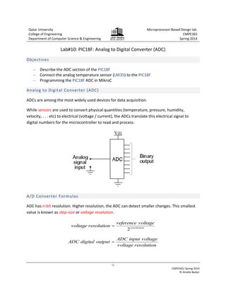
-1-
CMPE365/ Spring 2014
© Amelle Bedair
Qatar University
College of Engineering
Department of Computer Science & Engineering
Microprocessor Based Design lab.
CMPE365
Spring 2014
Lab#10: PIC18F: Analog to Digital Converter (ADC)
Objectives
‒ Describe the ADC section of the PIC18F
‒ Connect the analog temperature sensor (LM35) to the PIC18F
‒ Programming the PIC18F ADC in MikroC
Analog to Digital Converter (ADC)
ADCs are among the most widely used devices for data acquisition.
While sensors are used to convert physical quantities (temperature, pressure, humidity,
velocity, . . . etc) to electrical (voltage / current), the ADCs translate this electrical signal to
digital numbers for the microcontroller to read and process.
A/D Converter Formulas
ADC has n-bit resolution. Higher resolution, the ADC can detect smaller changes. This smallest
value is known as step-size or voltage resolution.
resolution
voltage
reference
resolution
voltage
2

resolution
voltage
voltage
input
ADC
output
digital
ADC 
-2-
CMPE365/ Spring 2014
© Amelle Bedair
What’s so important about voltage resolution?
Most important specification of ADCs is the voltage resolution. This specifies how accurately the
ADC measures the analog input signals. Common ADC are 8 bit, 10 bit and 12 bit. For example if
the reference voltage of ADC is 5V then:
‒ For an 8-bit ADC, voltage resolution = 528
 19 mV/bit
‒ For a 10-bit ADC, voltage resolution = 5210
 4.8mV/bit
So you can see that the 8-bit ADC can't tell the difference between 1mV and 18mV.
PIC18F ADC Features
 PIC18F45k22 includes 28 analog input channels
 The ADC allows conversion of an analog input signal to a 10-bit binary representation of
that signal.
For more information; refer to Section 17 in the datasheet
LM35 – Analog Temperature Sensor
The LM35 is a low-cost precision integrated-circuit temperature sensor, whose output voltage is
linearly proportional to the Celsius (Centigrade) temperature. It has a linear +10.0 mV/°C scale
factor and less than 60 μA current drain.
EasyPIC™ v7 board provides a separate socket (TS2) for the LM35 sensor in TO-92 plastic
packaging. Readings are done with microcontroller using single analog input line, which is
selected with jumper J25. Jumper connects the sensor with either RE2 or RE1 microcontroller
pins.
-3-
CMPE365/ Spring 2014
© Amelle Bedair
Task#1: The ADC module in PIC18F
In this task, you’ll program the PIC18F to read the voltage signal from the temperature sensor;
LM35 and display the ADC output through the 7-segment display units.
Task#1
1. Insert the LM35 in TS2 socket. Make sure that half-circle on the board’s silkscreen markings
matches the rounded part of the LM35 sensor. If you accidently connect the sensor the
other way, it can be permanently damaged and you might need to replace it with another
one.
2. Connect the J25 jumper so that the reading of LM35 is read by RE2 which is the same as
AN7. Make sure that no other device uses the selected analog line, because it may interfere
with the readings.
LM35 not connected LM35 connected to RE2 pin
Pin Number Pin Name Pin Details Pin Type Description
9 RE1/P3B/AN6
RE1 I Digital Input
AN6 I Analog Input
10 RE2/CCP5/AN7
RE2 I/O Digital I/O
AN7 I Analog Input
Source: Data sheet page#26
-4-
CMPE365/ Spring 2014
© Amelle Bedair
Task#2
Write the PIC18F C-code where the ADC takes the measurement of the temperature sensor
connected to RE2 (AN7) and displays the result (in binary format) through the eight LEDs
connected to PORTD. Finally, A press on RC0 turns-off the LEDs and the ADC after exiting the
while() loop.
Step#1
1. Open the Help (F1). In the Index tab, type in the keyword: adc_read and press the
Enter key.
An example. Taken from the help document
unsigned tmp; // A two byte integer 0 to 65535
...
tmp = ADC_Read(2); // Read analog value from channel 2
Begin
1) Set RC0 as digital input
2) Set PORTD as output
3) Set RE2 as analog input
Display through PORTD
Is RC0 push button pressed?
Turn off PORTD
End
Get the ADC reading
No Yes
-5-
CMPE365/ Spring 2014
© Amelle Bedair
2. Answer the following:
a. Prototype? unsigned adc_read(unsigned short channel);
b. Returned value? 10-bit unsigned value read from the specified channel .
c. What is meant by the channel? Parameter channel represents the channel from
which the analog value is to be acquired.
d. How many channels are there in PIC18F45k22? 28 (mentioned on page 2)
e. Which channel will you use? Either 6 (RE1) or 7 (RE2)
f. Program requirement before using the function? Be sure to configure the appropriate
TRISx bits to designate pins as inputs.
g. What is the adc_init function for?
This routine initializes PIC’s internal ADC module
h. How can you display this 10-bit value through PORTD (8-bit)?
If you say; PORTD=ADC_read(. . .); then only the first eight-bits are sent to
PORTD. The two leftmost bits coming from the 10-bit ADC are ignored.
i. Is that convenient for such an application? Yes. 8-bits are enough to measure
environmental temperatures.
3. Complete the following using the comments as reference:
1.
2.
3.
4.
5.
6.
7.
8.
9.
10.
11.
12.
13.
14.
15.
16.
17.
18.
void main()
{
unsigned from_adc; // A 16-bit variable
TRISD = _____ ; // PORTD direction: Out
TRISE.B2 = __ ; // RE2 direction: In
ANSELE.B2 = __ ; // RE2 input type: Analog
TRISC.B0 = __ ; // RC0 Direction: In
ANSELC.B0 = __ ; // RC0 input type : Digital
adc_init(); // Initialize the A/D converter
while(1)
{
if( __________ ) break; // Is the push-button is pressed?
from_adc=adc_read(____); // convert from analog to digital
__________________ ; // Display through PORTD
delay_ms(20); // A short pause
}
_________________ ; // turn off all LEDs
}
-6-
CMPE365/ Spring 2014
© Amelle Bedair
4. On the Library Manager, check as shown:
Step#2: Run & Read
Condition PORTD in hex Calculated Temperature
At room temperature
Between two figures
To fill the 3rd
column, you need to get the conversion formula. Look at the following figure:
10
4.8
from_adc
C)
e(
Temperatur



Step#2: Discuss
Can from the code you have getting as shown? Can you use PORTD = display(from_adc)
command? Justify.
LM35
10mv/C
ADC
4.8 mv/bit
28C
280 mv 58
CPU
0011:1110
0100:1000
62*4.8/10
we need to make the function and convert it to the real temprature and then
display it on the 7 segment display

lab_ADC.pdf

  • 1.
    -1- CMPE365/ Spring 2014 ©Amelle Bedair Qatar University College of Engineering Department of Computer Science & Engineering Microprocessor Based Design lab. CMPE365 Spring 2014 Lab#10: PIC18F: Analog to Digital Converter (ADC) Objectives ‒ Describe the ADC section of the PIC18F ‒ Connect the analog temperature sensor (LM35) to the PIC18F ‒ Programming the PIC18F ADC in MikroC Analog to Digital Converter (ADC) ADCs are among the most widely used devices for data acquisition. While sensors are used to convert physical quantities (temperature, pressure, humidity, velocity, . . . etc) to electrical (voltage / current), the ADCs translate this electrical signal to digital numbers for the microcontroller to read and process. A/D Converter Formulas ADC has n-bit resolution. Higher resolution, the ADC can detect smaller changes. This smallest value is known as step-size or voltage resolution. resolution voltage reference resolution voltage 2  resolution voltage voltage input ADC output digital ADC 
  • 2.
    -2- CMPE365/ Spring 2014 ©Amelle Bedair What’s so important about voltage resolution? Most important specification of ADCs is the voltage resolution. This specifies how accurately the ADC measures the analog input signals. Common ADC are 8 bit, 10 bit and 12 bit. For example if the reference voltage of ADC is 5V then: ‒ For an 8-bit ADC, voltage resolution = 528  19 mV/bit ‒ For a 10-bit ADC, voltage resolution = 5210  4.8mV/bit So you can see that the 8-bit ADC can't tell the difference between 1mV and 18mV. PIC18F ADC Features  PIC18F45k22 includes 28 analog input channels  The ADC allows conversion of an analog input signal to a 10-bit binary representation of that signal. For more information; refer to Section 17 in the datasheet LM35 – Analog Temperature Sensor The LM35 is a low-cost precision integrated-circuit temperature sensor, whose output voltage is linearly proportional to the Celsius (Centigrade) temperature. It has a linear +10.0 mV/°C scale factor and less than 60 μA current drain. EasyPIC™ v7 board provides a separate socket (TS2) for the LM35 sensor in TO-92 plastic packaging. Readings are done with microcontroller using single analog input line, which is selected with jumper J25. Jumper connects the sensor with either RE2 or RE1 microcontroller pins.
  • 3.
    -3- CMPE365/ Spring 2014 ©Amelle Bedair Task#1: The ADC module in PIC18F In this task, you’ll program the PIC18F to read the voltage signal from the temperature sensor; LM35 and display the ADC output through the 7-segment display units. Task#1 1. Insert the LM35 in TS2 socket. Make sure that half-circle on the board’s silkscreen markings matches the rounded part of the LM35 sensor. If you accidently connect the sensor the other way, it can be permanently damaged and you might need to replace it with another one. 2. Connect the J25 jumper so that the reading of LM35 is read by RE2 which is the same as AN7. Make sure that no other device uses the selected analog line, because it may interfere with the readings. LM35 not connected LM35 connected to RE2 pin Pin Number Pin Name Pin Details Pin Type Description 9 RE1/P3B/AN6 RE1 I Digital Input AN6 I Analog Input 10 RE2/CCP5/AN7 RE2 I/O Digital I/O AN7 I Analog Input Source: Data sheet page#26
  • 4.
    -4- CMPE365/ Spring 2014 ©Amelle Bedair Task#2 Write the PIC18F C-code where the ADC takes the measurement of the temperature sensor connected to RE2 (AN7) and displays the result (in binary format) through the eight LEDs connected to PORTD. Finally, A press on RC0 turns-off the LEDs and the ADC after exiting the while() loop. Step#1 1. Open the Help (F1). In the Index tab, type in the keyword: adc_read and press the Enter key. An example. Taken from the help document unsigned tmp; // A two byte integer 0 to 65535 ... tmp = ADC_Read(2); // Read analog value from channel 2 Begin 1) Set RC0 as digital input 2) Set PORTD as output 3) Set RE2 as analog input Display through PORTD Is RC0 push button pressed? Turn off PORTD End Get the ADC reading No Yes
  • 5.
    -5- CMPE365/ Spring 2014 ©Amelle Bedair 2. Answer the following: a. Prototype? unsigned adc_read(unsigned short channel); b. Returned value? 10-bit unsigned value read from the specified channel . c. What is meant by the channel? Parameter channel represents the channel from which the analog value is to be acquired. d. How many channels are there in PIC18F45k22? 28 (mentioned on page 2) e. Which channel will you use? Either 6 (RE1) or 7 (RE2) f. Program requirement before using the function? Be sure to configure the appropriate TRISx bits to designate pins as inputs. g. What is the adc_init function for? This routine initializes PIC’s internal ADC module h. How can you display this 10-bit value through PORTD (8-bit)? If you say; PORTD=ADC_read(. . .); then only the first eight-bits are sent to PORTD. The two leftmost bits coming from the 10-bit ADC are ignored. i. Is that convenient for such an application? Yes. 8-bits are enough to measure environmental temperatures. 3. Complete the following using the comments as reference: 1. 2. 3. 4. 5. 6. 7. 8. 9. 10. 11. 12. 13. 14. 15. 16. 17. 18. void main() { unsigned from_adc; // A 16-bit variable TRISD = _____ ; // PORTD direction: Out TRISE.B2 = __ ; // RE2 direction: In ANSELE.B2 = __ ; // RE2 input type: Analog TRISC.B0 = __ ; // RC0 Direction: In ANSELC.B0 = __ ; // RC0 input type : Digital adc_init(); // Initialize the A/D converter while(1) { if( __________ ) break; // Is the push-button is pressed? from_adc=adc_read(____); // convert from analog to digital __________________ ; // Display through PORTD delay_ms(20); // A short pause } _________________ ; // turn off all LEDs }
  • 6.
    -6- CMPE365/ Spring 2014 ©Amelle Bedair 4. On the Library Manager, check as shown: Step#2: Run & Read Condition PORTD in hex Calculated Temperature At room temperature Between two figures To fill the 3rd column, you need to get the conversion formula. Look at the following figure: 10 4.8 from_adc C) e( Temperatur    Step#2: Discuss Can from the code you have getting as shown? Can you use PORTD = display(from_adc) command? Justify. LM35 10mv/C ADC 4.8 mv/bit 28C 280 mv 58 CPU 0011:1110 0100:1000 62*4.8/10 we need to make the function and convert it to the real temprature and then display it on the 7 segment display