This document provides standards for electrical engineering systems in GSA public buildings. It discusses general design approaches, applicable codes and standards, commissioning requirements, and guidelines for placing electrical and communications systems within buildings. Standards are provided for horizontal and vertical distribution of power and communications infrastructure, including separate pathways for different systems. Commissioning practices are to be coordinated between the electrical engineer and other project roles to test programmed performance goals.
![E L E C T R I C A L E N G I N E E R I N G
Revised March 2003 – PBS-P100 Site Distribution 6.8
191
Where it is necessary to run communication cables
alongside power cables, two separate systems must be
provided with separate manhole compartments. The
same holds true for normal and emergency power cables.
Ductbanks should be spaced at least 300 mm (1 foot)
apart. Site entrance facilities including ductbanks and
manholes must comply with requirements stated in
Federal Information Processing Standard 175: Federal
Building Standard for Telecommunication Pathways and
Spaces (see also EIA/TIA [Electronic Industrial
Association/Telecommunication Industry Association]
Standard 568-A and related bulletins)
Electrical and communication ducts should be kept clear
of all other underground utilities, especially high
temperature water or steam.
Duct Sizes. Ducts should be sized as required for the
number and size of cables. Inner ducts must be provided
inside communication ducts wherever fiber optic cables
will be used. A sufficient number of spare ducts should be
included for planned future expansion; in addition, a
minimum of 25 percent spare ducts must be provided for
unknown future expansion.
Manholes. Manholes should be spaced no farther than
150 m (500 feet) apart for straight runs. The distance
between the service entrance and the first manhole should
not exceed 30 m (100 feet). Double manholes should be
used where electric power and communication lines
follow the same route. Separate manholes should be
provided for low and medium voltage systems. Manholes
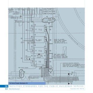
6.8 Site Distribution
Exterior distribution systems must be either direct buried
conduit or concrete encased conduit systems. Cable
selection should be based on all aspects of cable operation
and the installation environment, including corrosion,
ambient heat, rodent attack, pulling tensions, and
potential mechanical abuse and seismic activity.
Direct Buried Conduit. Direct buried PVC, coated
intermediate metallic conduit (IMC) or rigid galvanized
steel (RGS) is appropriate for the distribution of branch
circuits. Direct buried cable should not be used.
Concrete-Encased Ductbank. Concrete-encased
ductbanks should be used where many circuits follow the
same route, for runs under permanent hard pavements
and where service reliability is paramount, such as service
entrances.
Duct line routes should be selected to balance maximum
flexibility with minimum cost and to avoid foundations
of other buildings and other structures. Ducts should be
provided with a cover of at least 600 mm (24 inches).
Ductbanks under railroads should be reinforced. Ducts
should slope 4 percent toward manholes. Changes in
direction should be by sweeps with a radius of 7.5 m
(25 feet) or more. Stub-ups into electrical equipment may
be installed with manufactured elbows. Duct line routes
should be selected to balance maximum flexibility with
minimum cost and to avoid foundations of other buildings
and other structures.](https://image.slidesharecdn.com/6electricalengineeringr2-e-n1u0z5rdz-i34k-pr-151118204215-lva1-app6892/85/6-electrical-engineering_r2-e-n1_u_0z5rdz-i34k-pr-13-320.jpg)