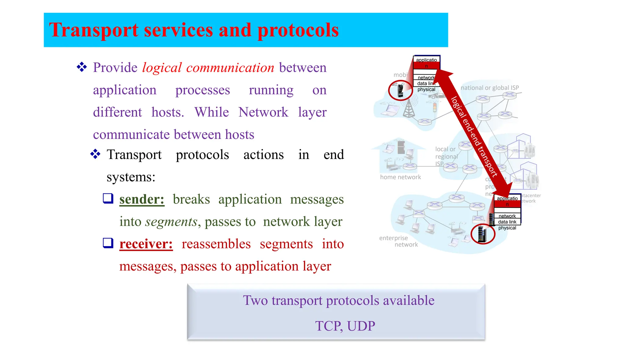
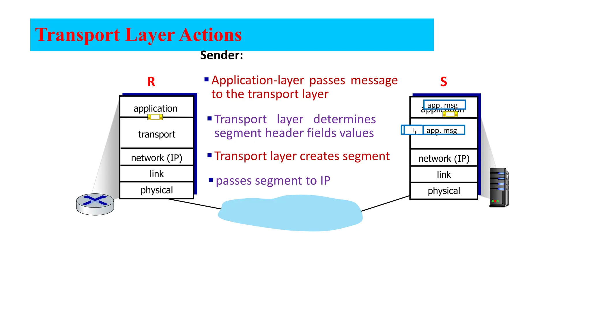
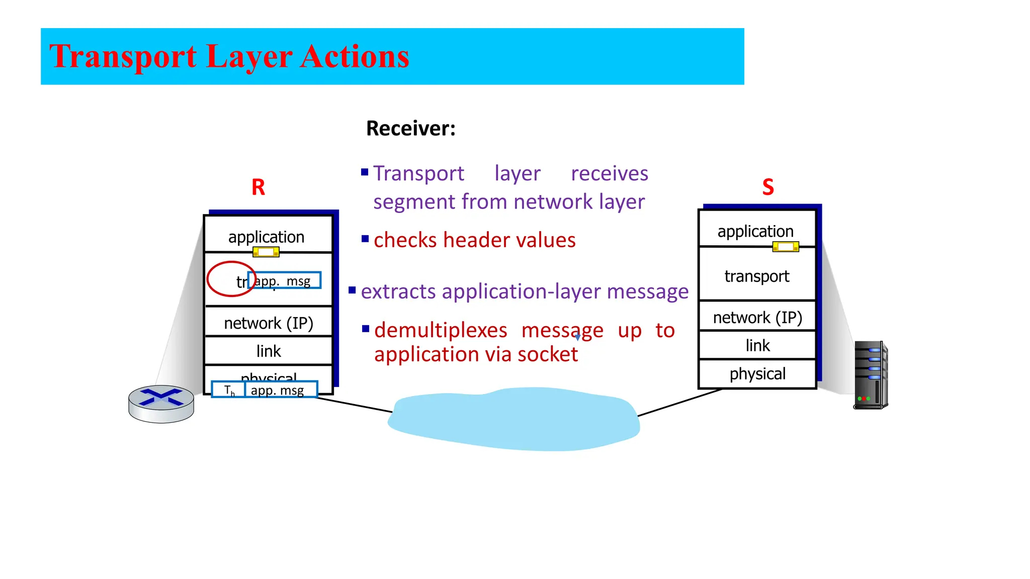
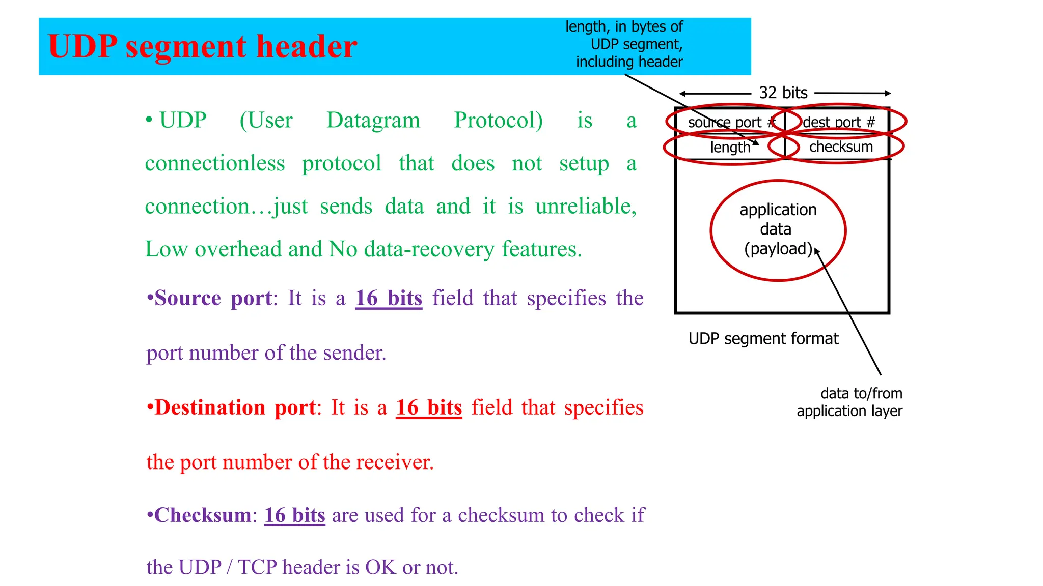
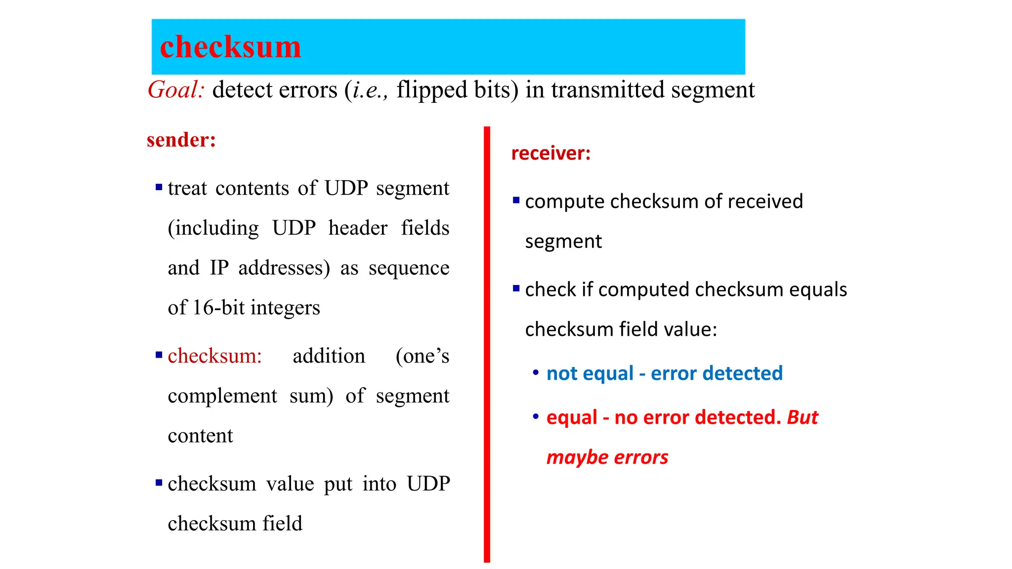
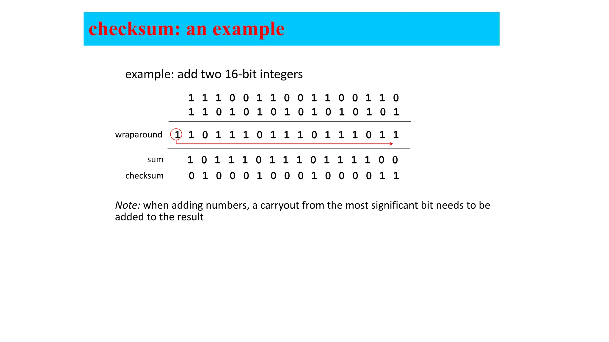
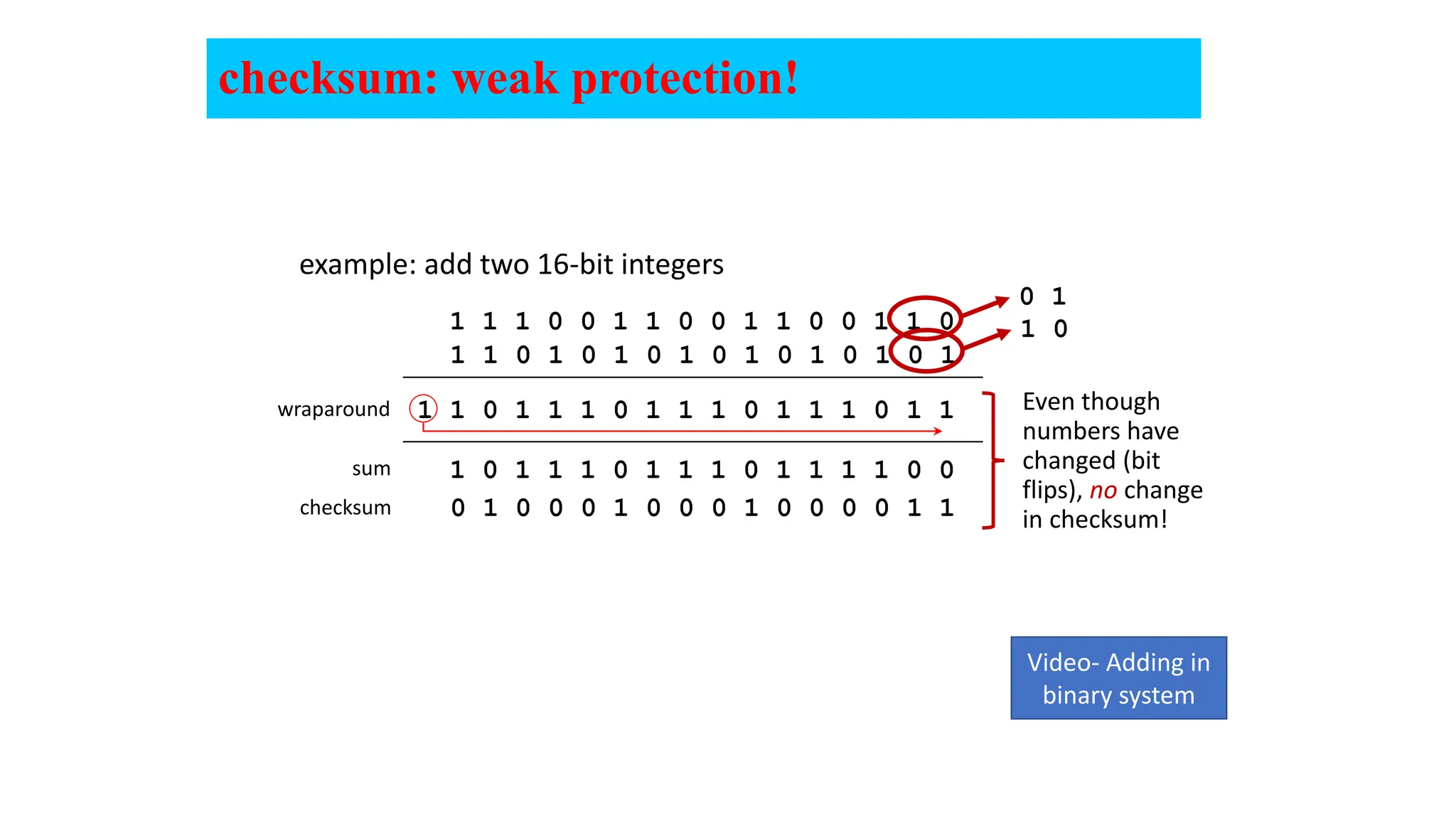
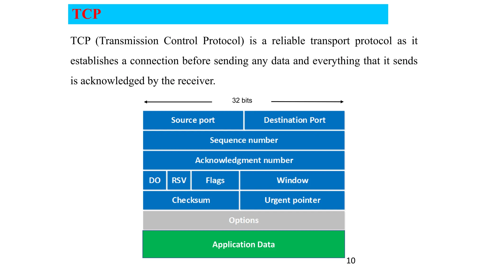
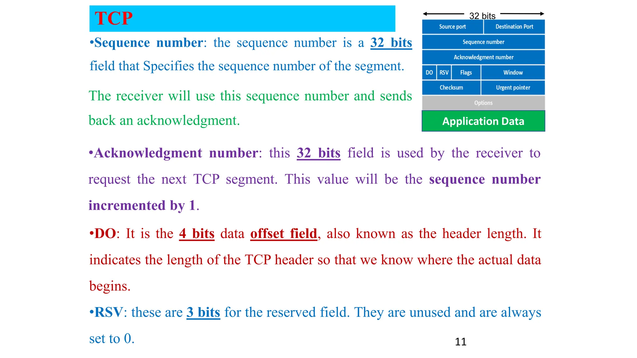
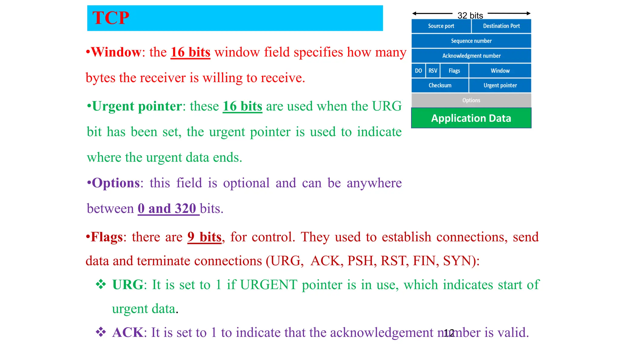
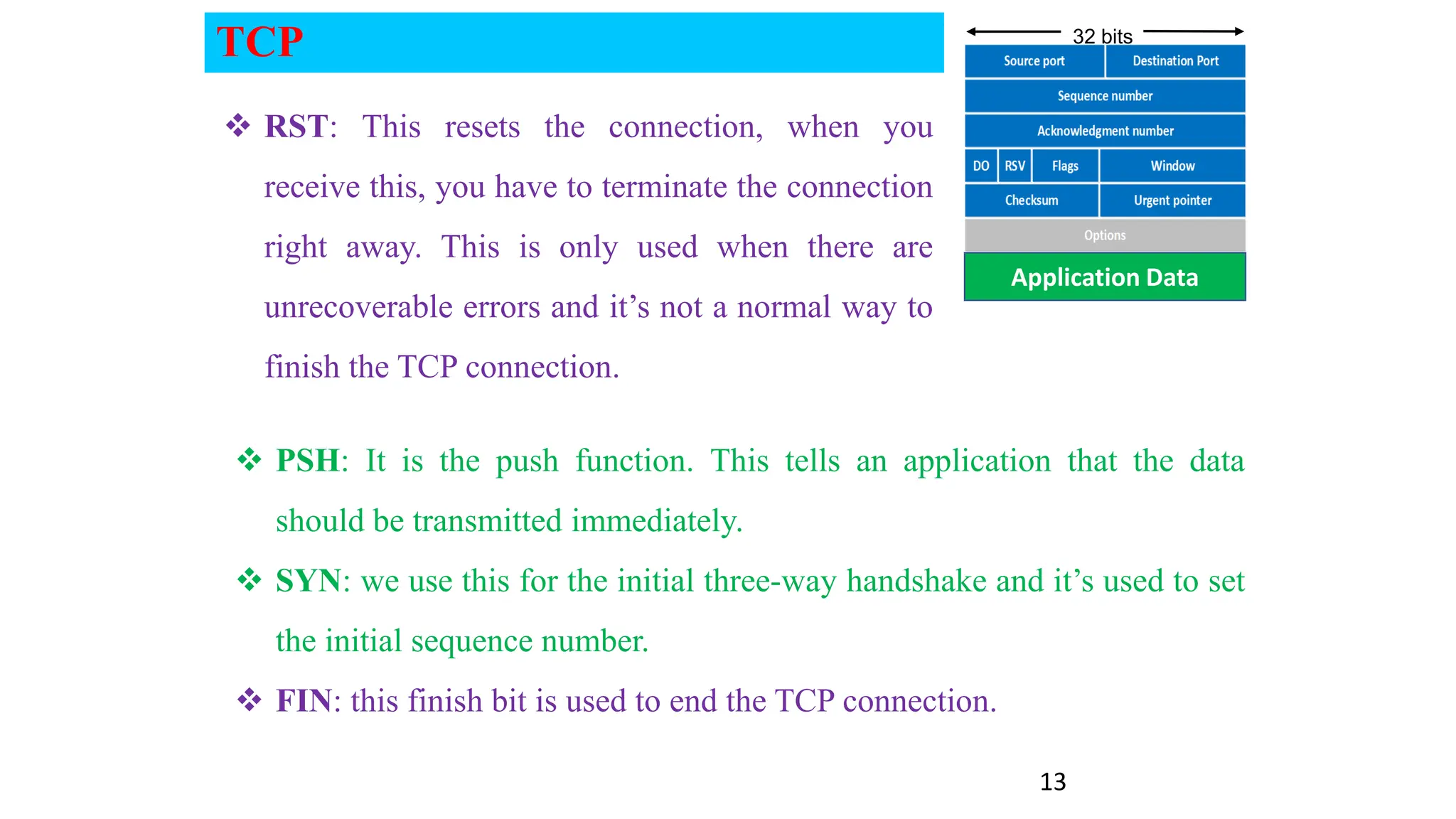
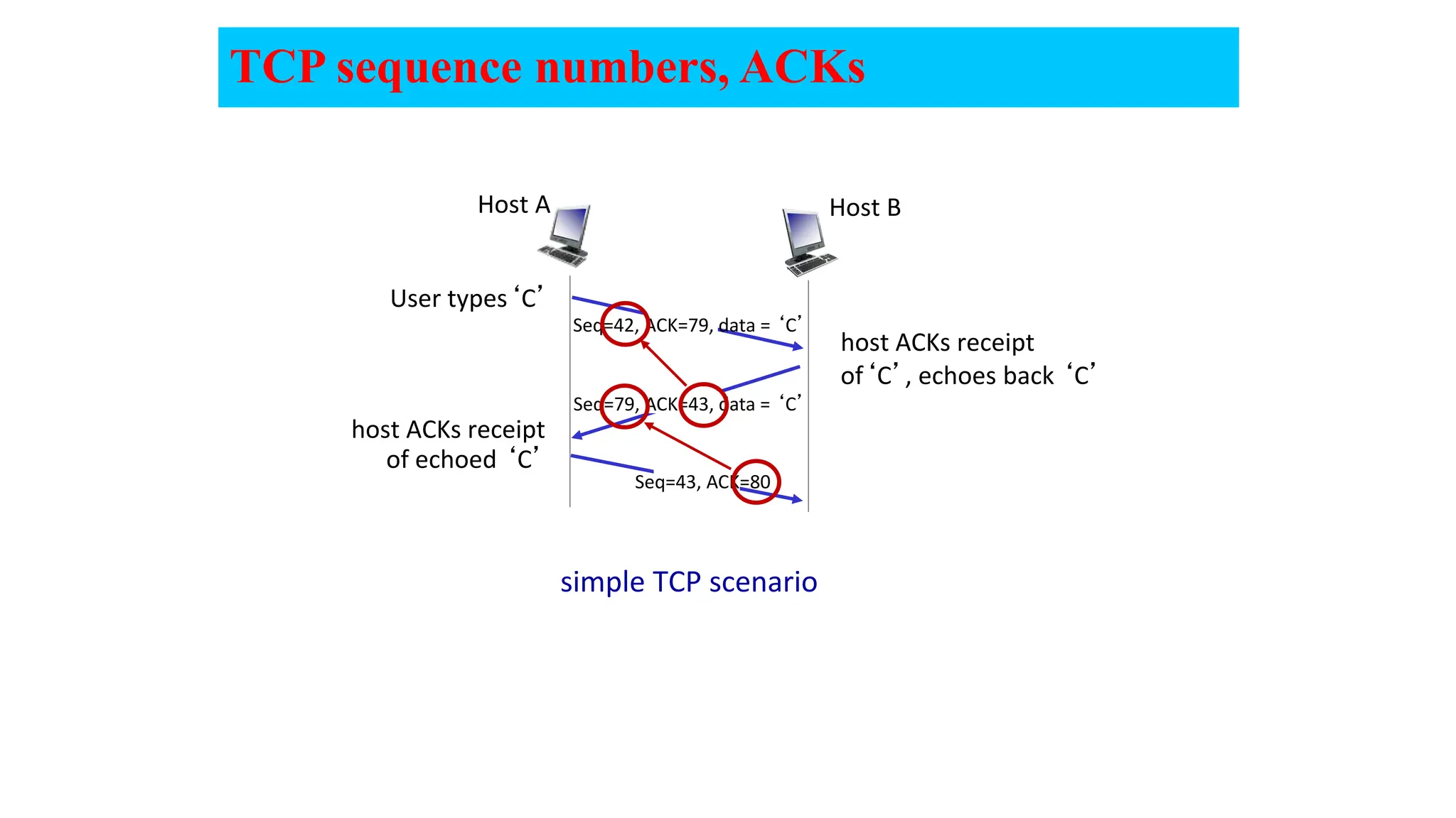
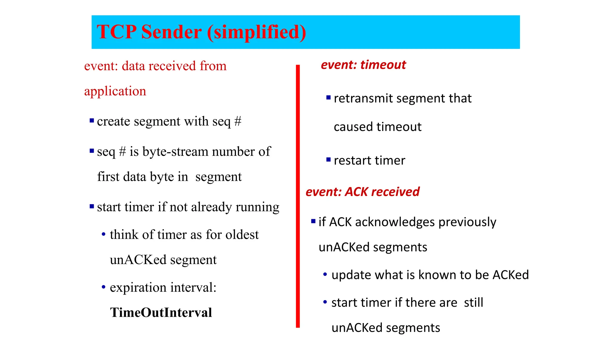
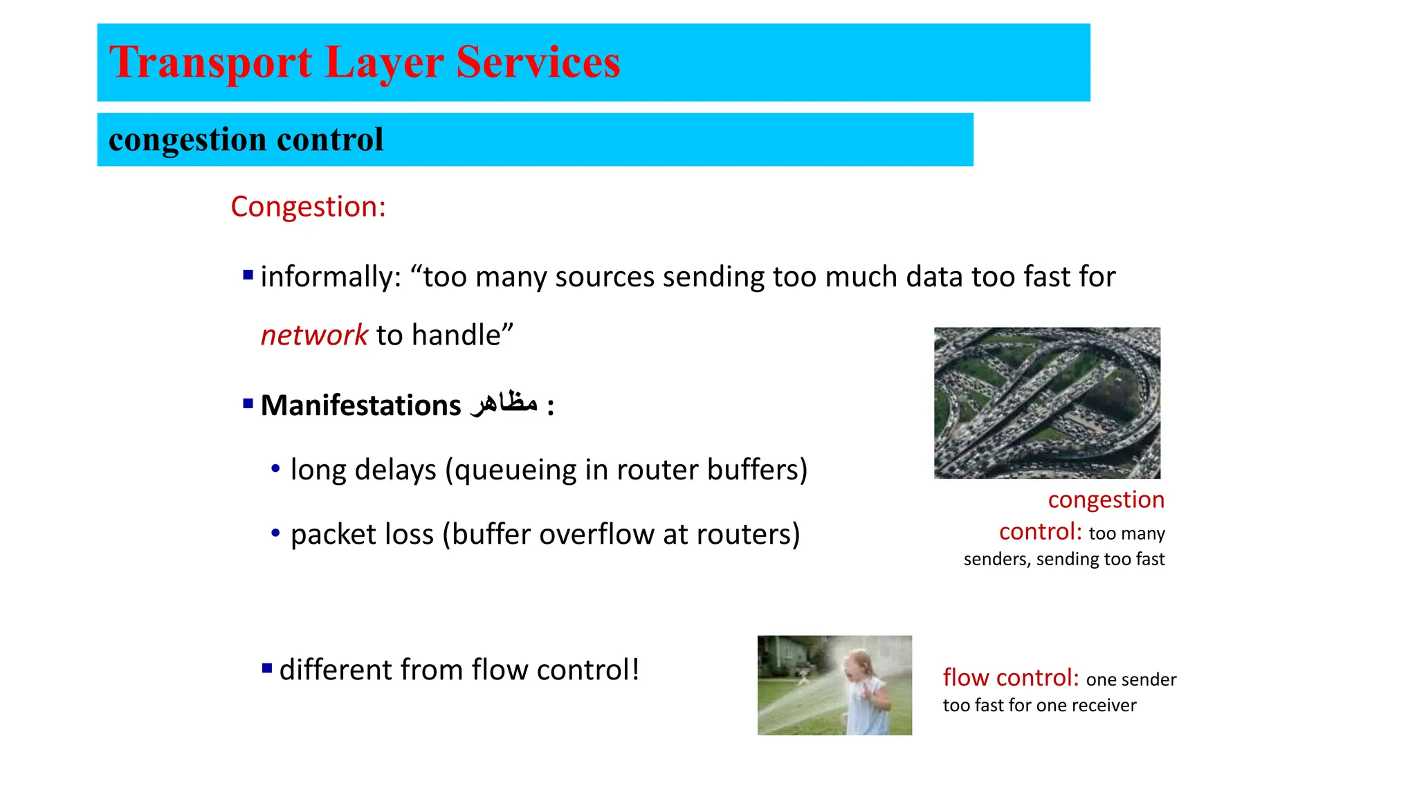
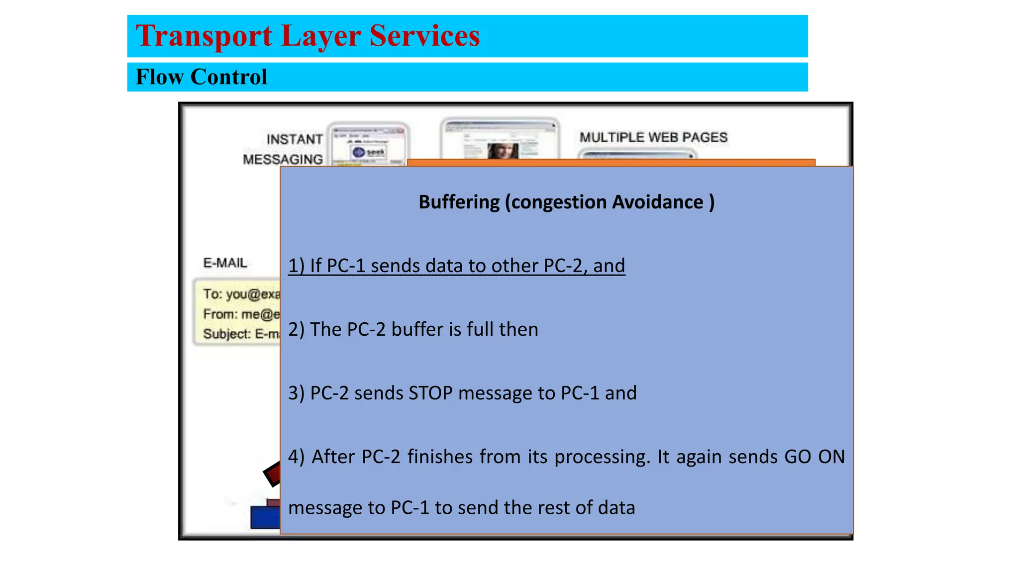
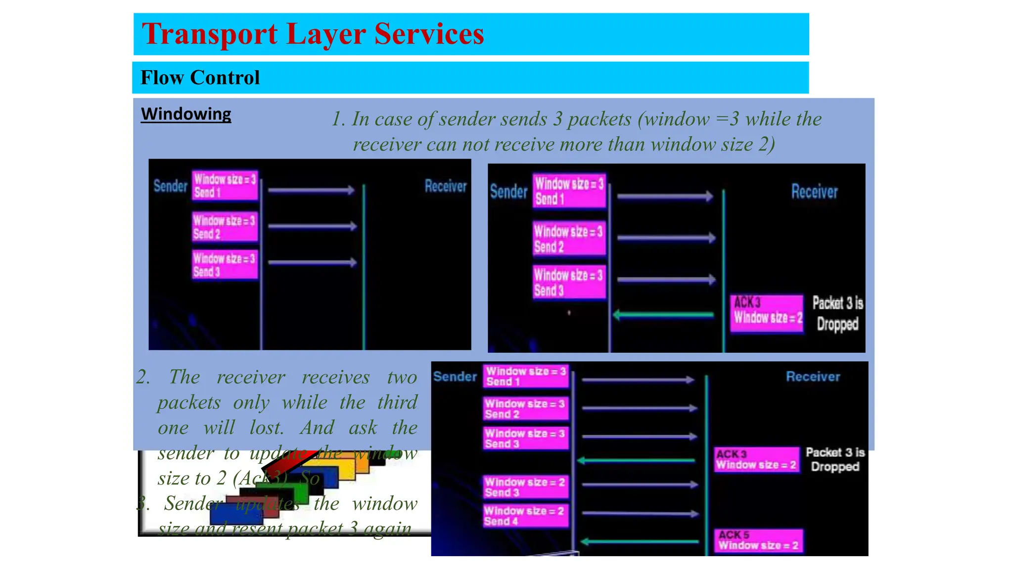
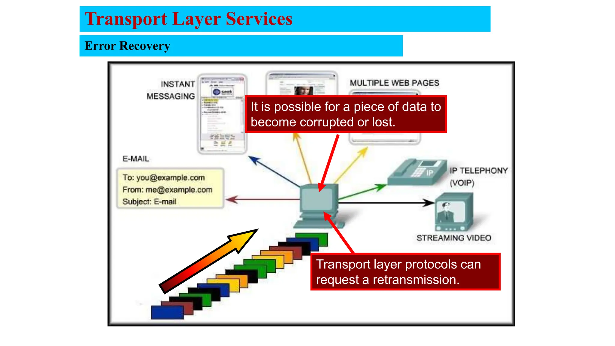
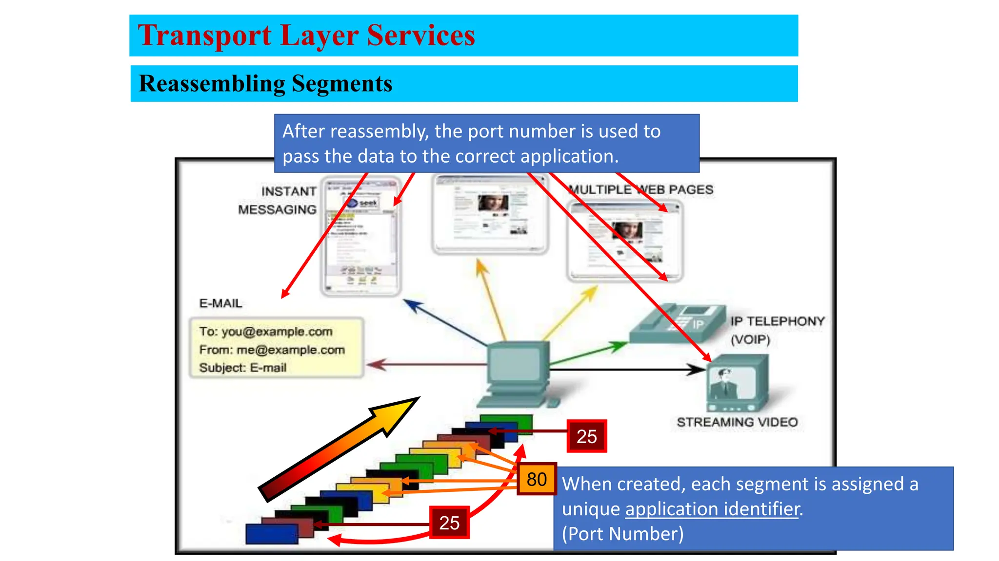
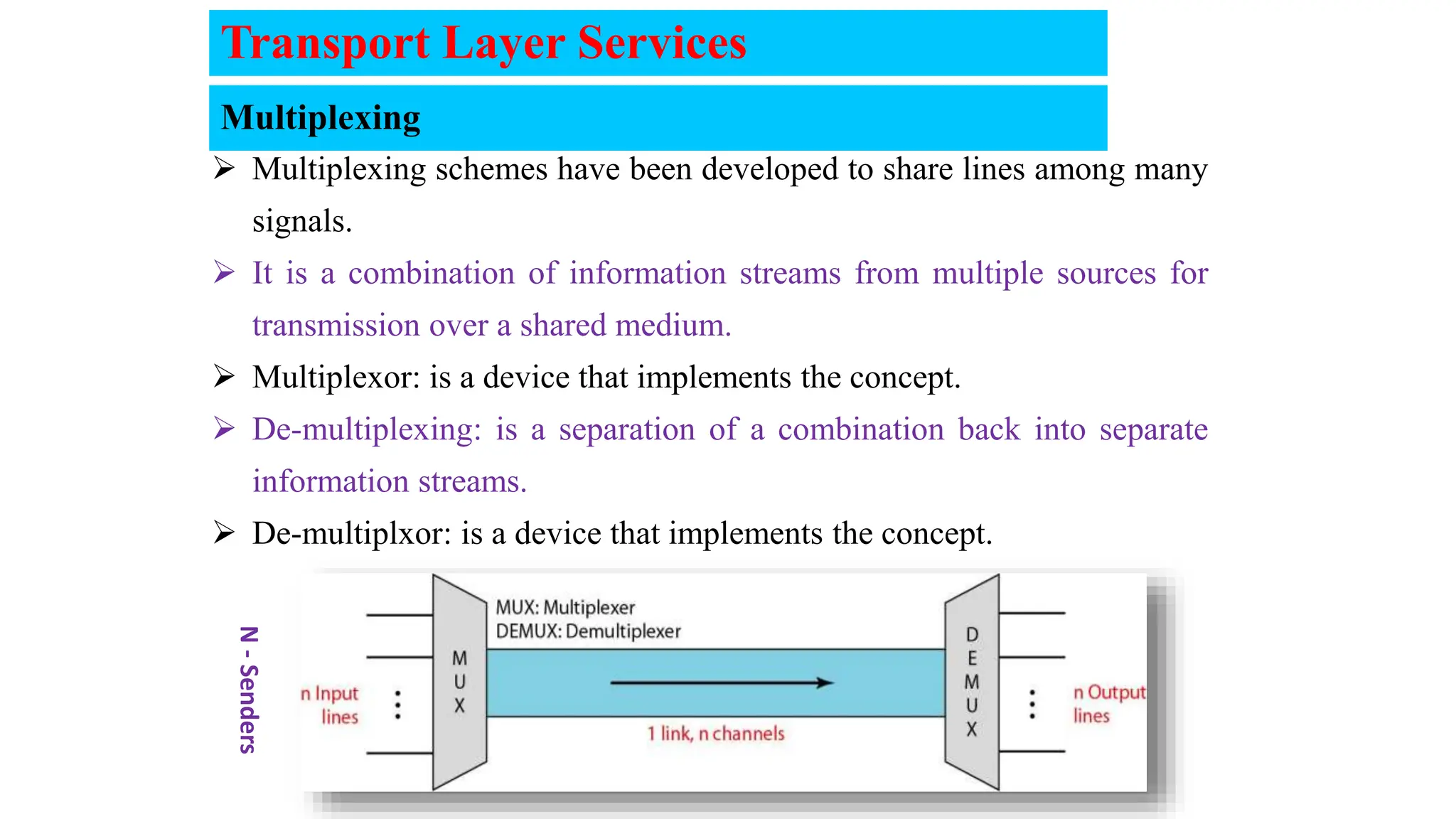
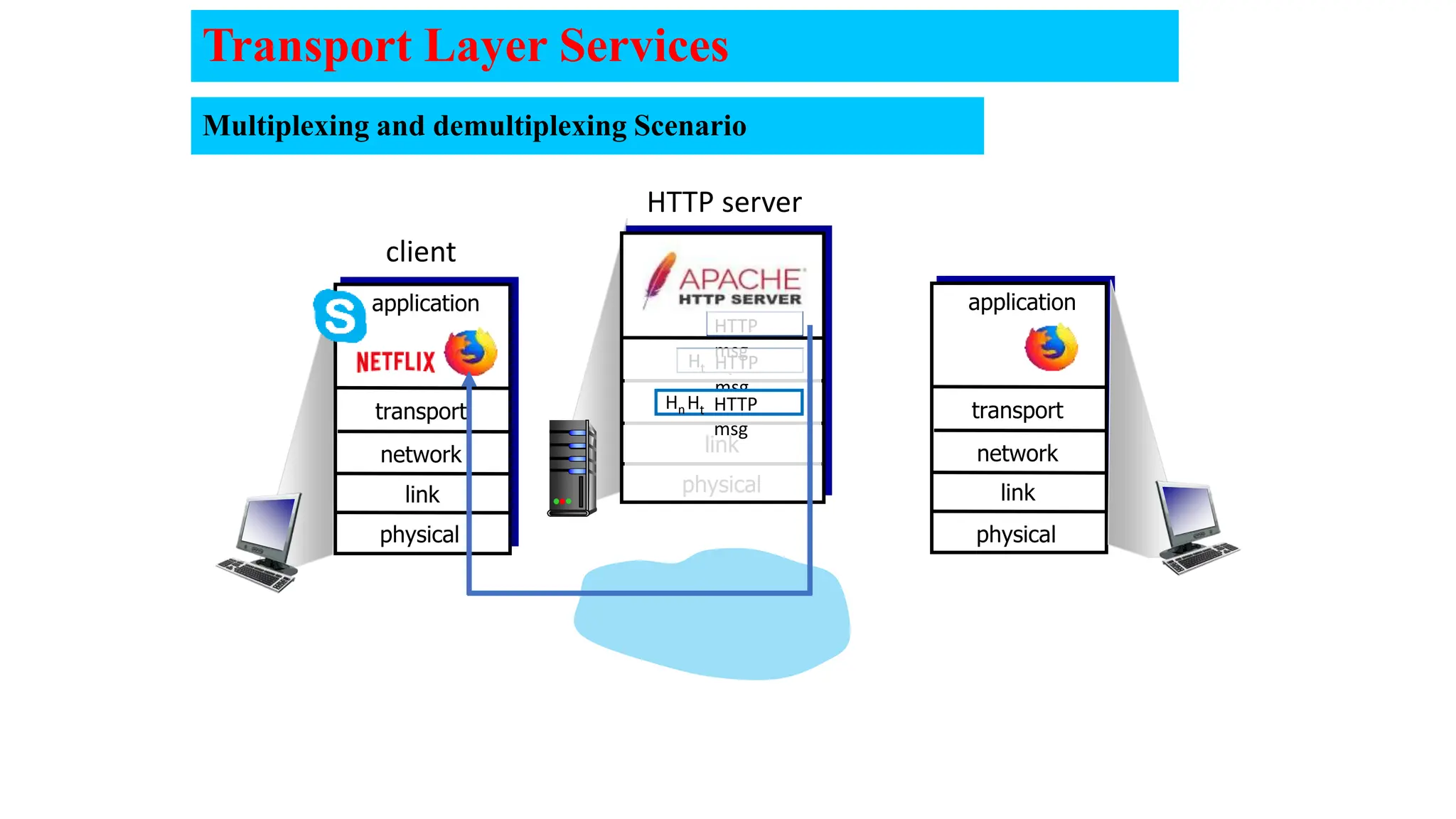
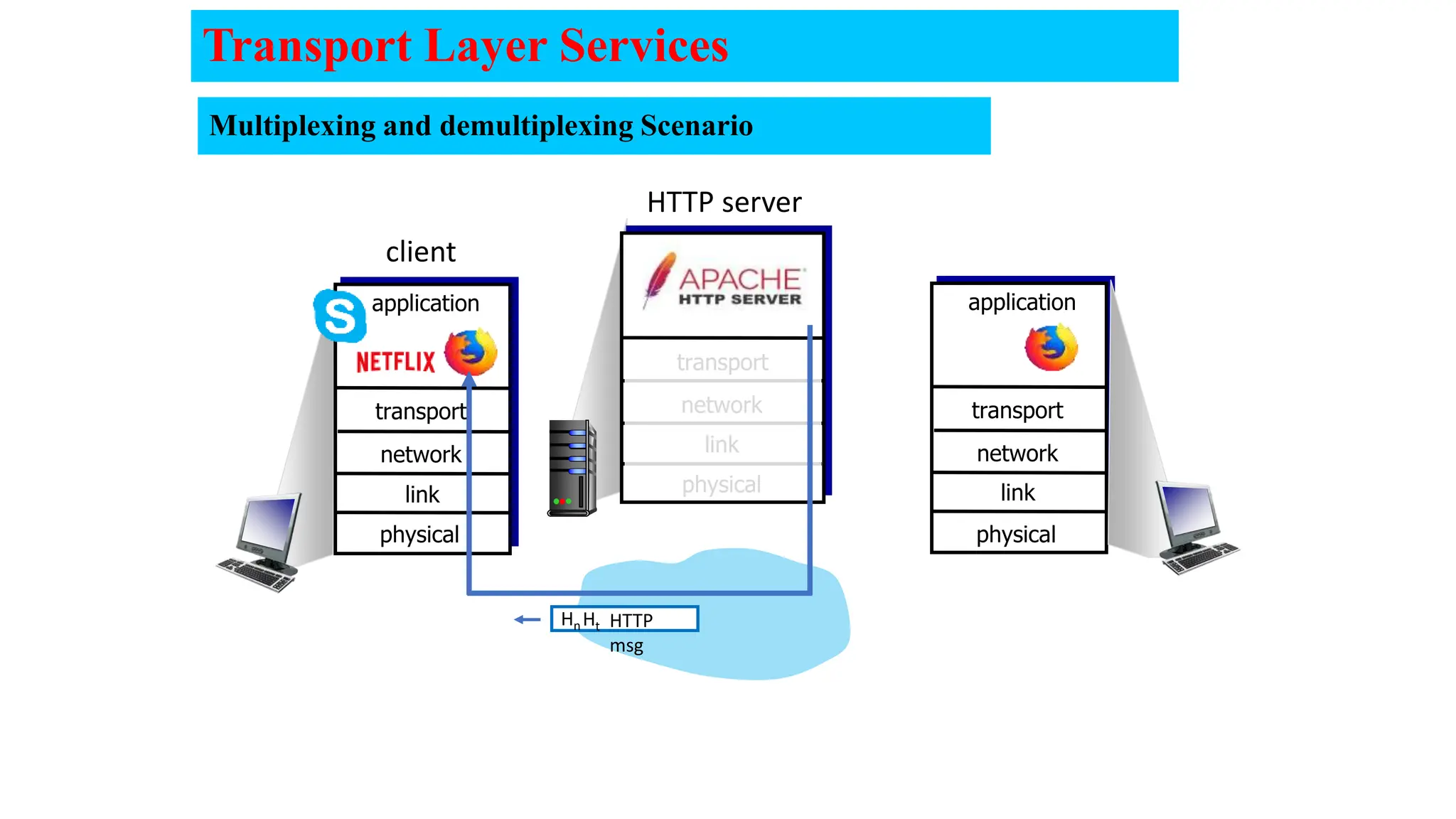
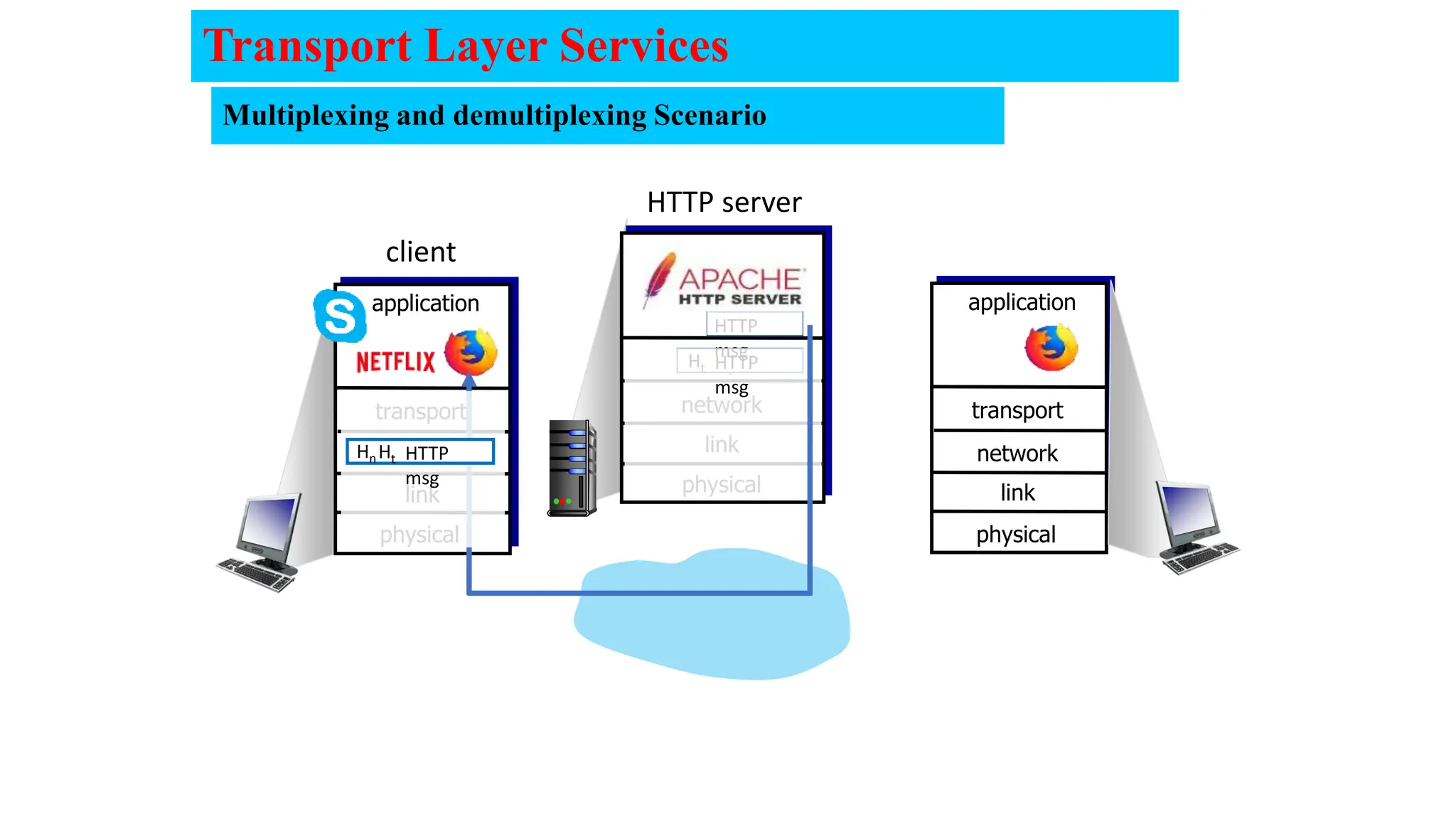
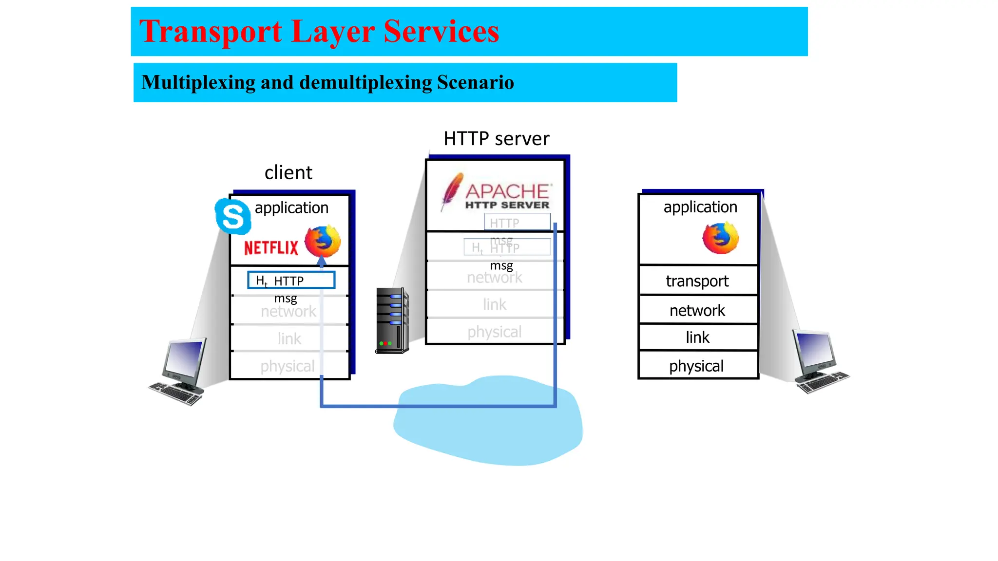
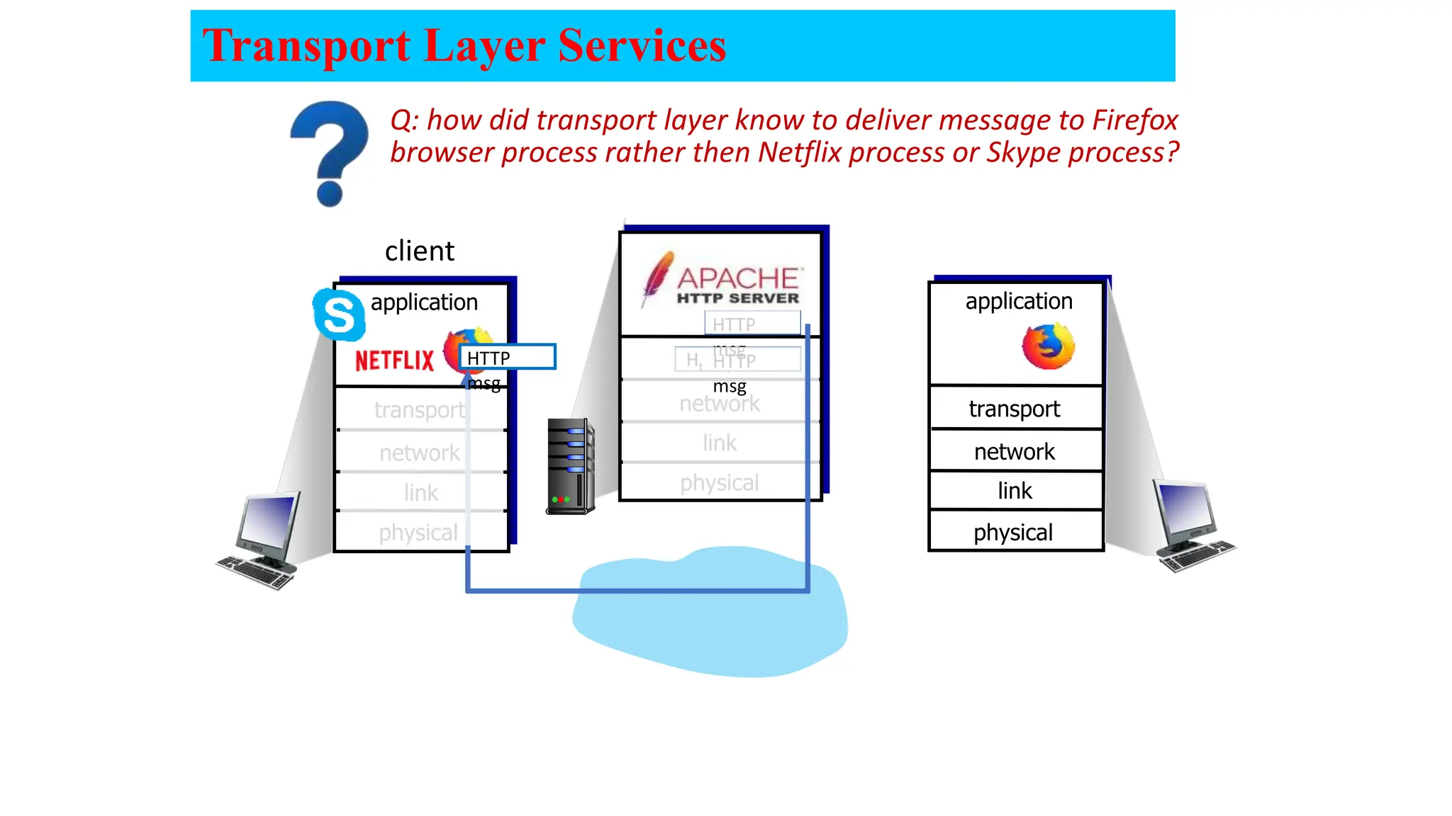
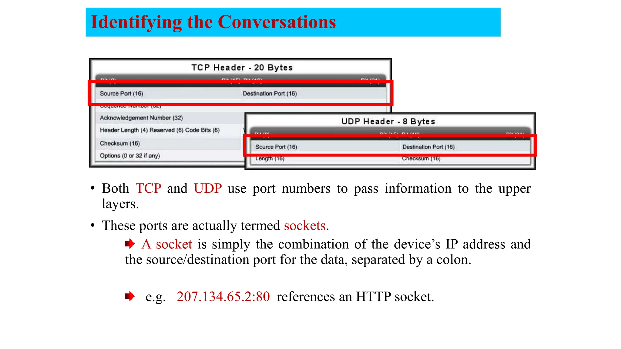
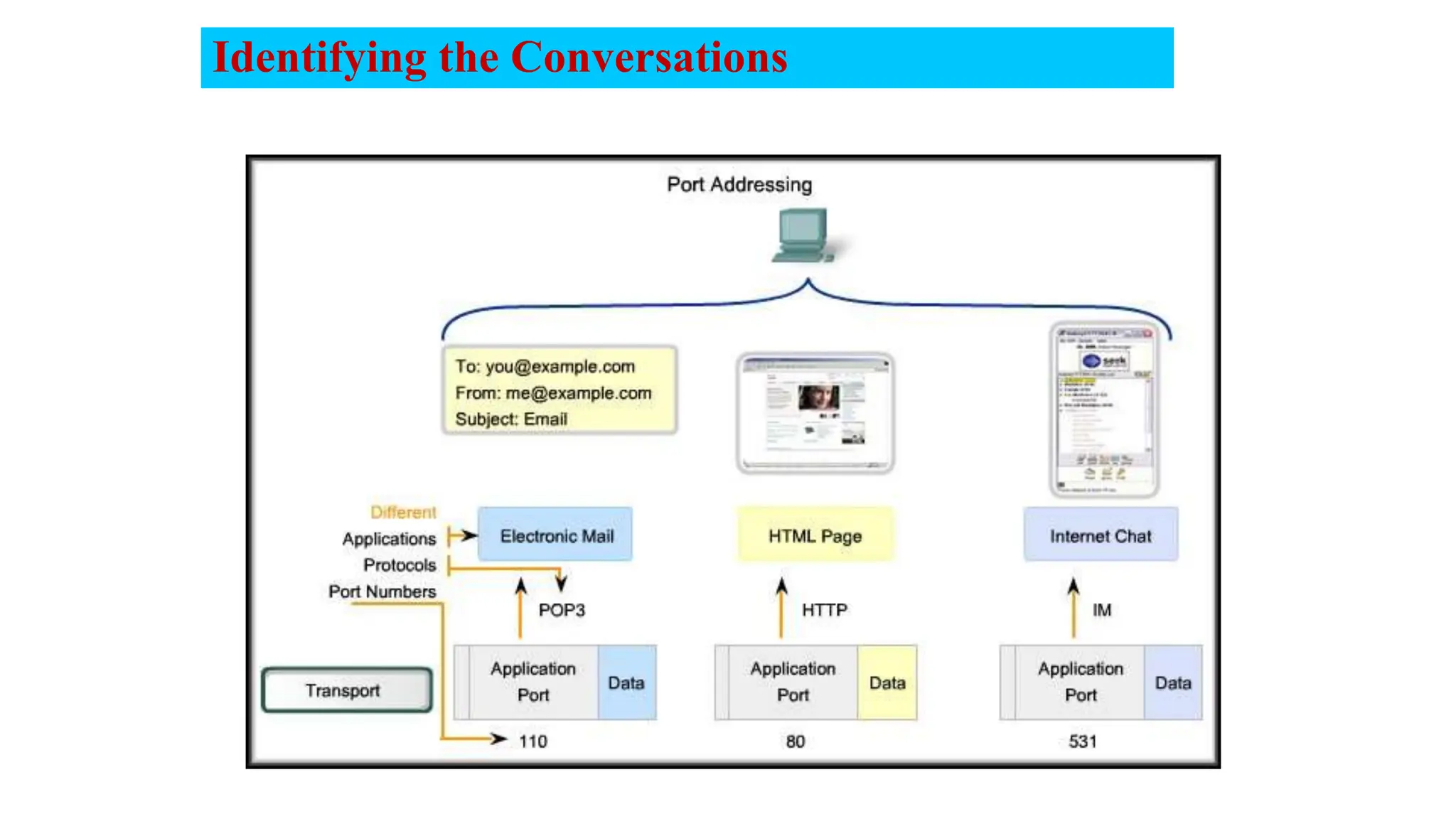
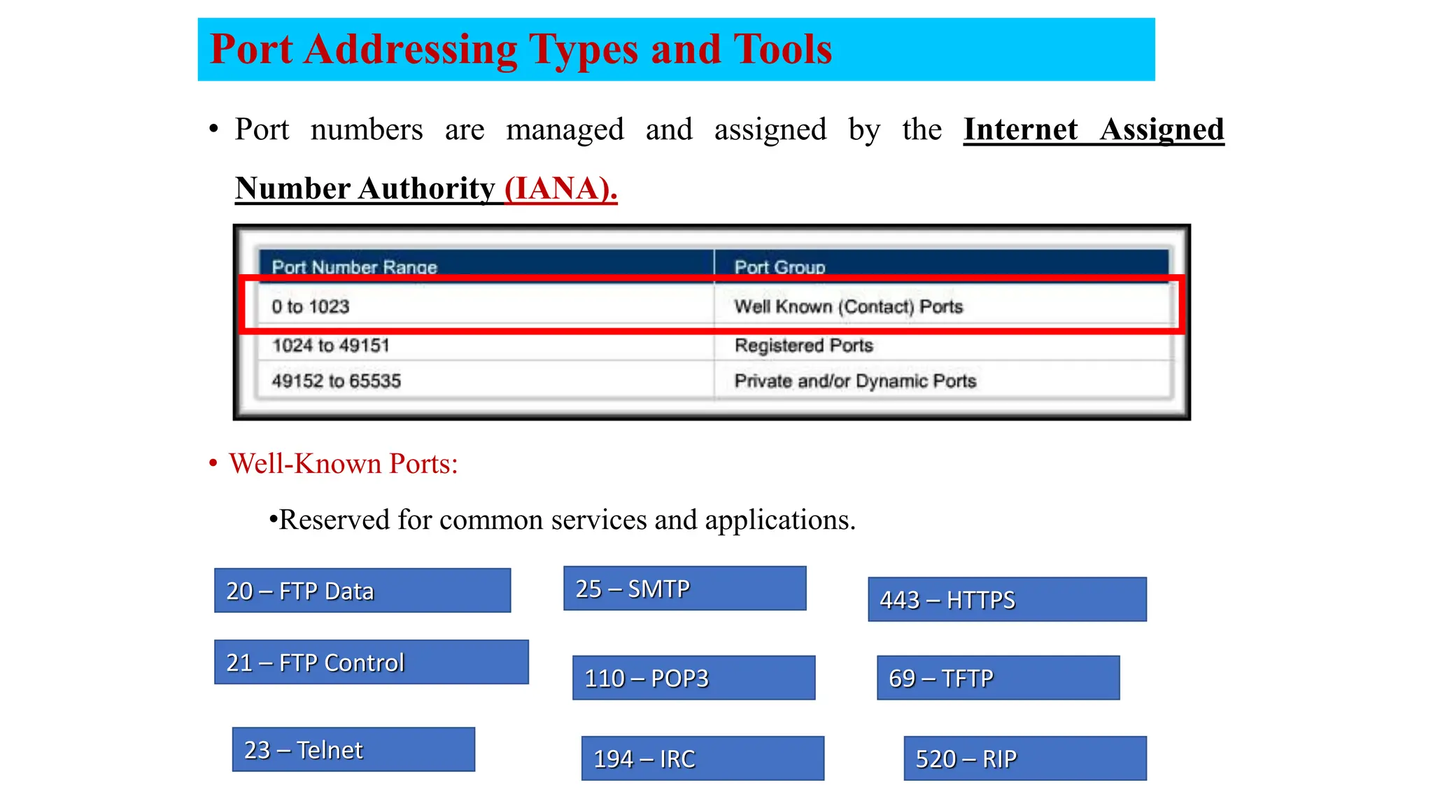
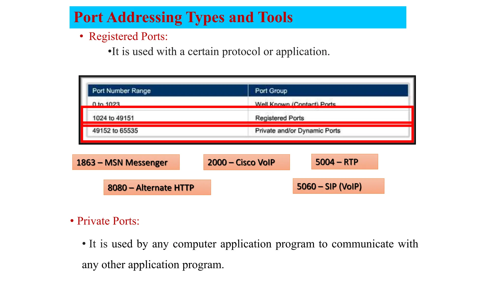
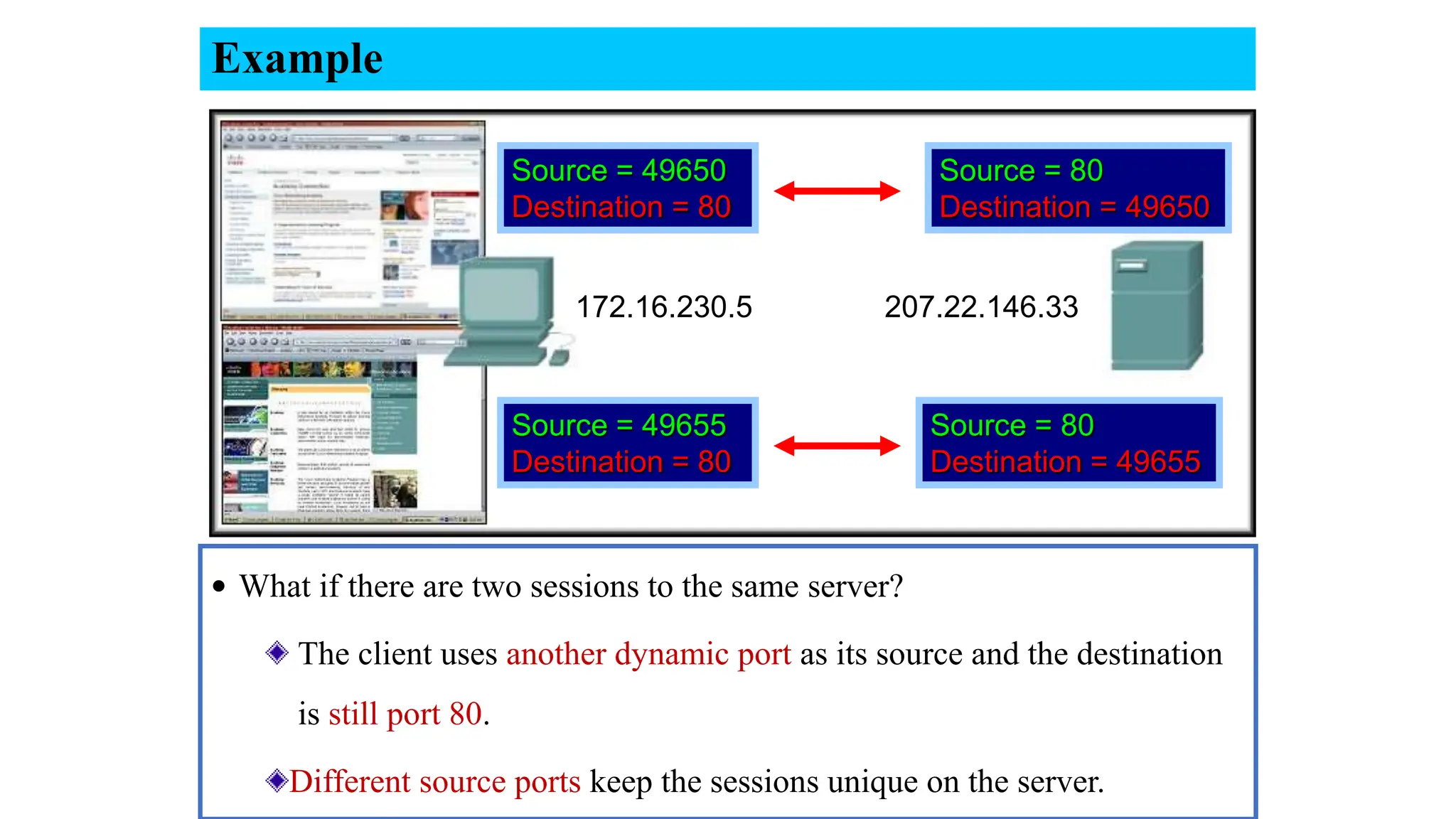
Computer Networks
LEC #2
Communicating Over the
Network
Computer Networks
LEC #5
Transport Layer
Lecture
Outlines
 Transport Layer.
 Transport Layer Protocols
Transport services and protocols
 Provide logical communication between
application processes running on
different hosts. While Network layer
communicate between hosts
mobile network
home network
enterprise
network
national or global ISP
local or
regional
ISP
datacenter
network
content
provider
network
applicatio
n
transport
network
data link
physical
applicatio
n
transport
network
data link
physical
 Transport protocols actions in end
systems:
 sender: breaks application messages
into segments, passes to network layer
 receiver: reassembles segments into
messages, passes to application layer
Two transport protocols available
TCP, UDP
physical
link
network (IP)
application
physical
link
network (IP)
application
transport
Transport Layer Actions
Sender:
app. msg
Application-layer passes message
to the transport layer
Transport layer determines
segment header fields values
Transport layer creates segment
passes segment to IP
transport
Th
Th app. msg
S
R
physical
link
network (IP)
application
physical
link
network (IP)
application
transport
transport
Receiver:
app. msg
extracts application-layer message
checks header values
Transport layer receives
segment from network layer
Th app. msg
demultiplexes message up to
application via socket
Transport Layer Actions
S
R
UDP segment header
source port # dest port #
32 bits
application
data
(payload)
UDP segment format
length checksum
length, in bytes of
UDP segment,
including header
data to/from
application layer
•Source port: It is a 16 bits field that specifies the
port number of the sender.
•Destination port: It is a 16 bits field that specifies
the port number of the receiver.
•Checksum: 16 bits are used for a checksum to check if
the UDP / TCP header is OK or not.
• UDP (User Datagram Protocol) is a
connectionless protocol that does not setup a
connection…just sends data and it is unreliable,
Low overhead and No data-recovery features.
checksum
sender:
 treat contents of UDP segment
(including UDP header fields
and IP addresses) as sequence
of 16-bit integers
 checksum: addition (one’s
complement sum) of segment
content
 checksum value put into UDP
checksum field
receiver:
 compute checksum of received
segment
 check if computed checksum equals
checksum field value:
• not equal - error detected
• equal - no error detected. But
maybe errors
Goal: detect errors (i.e., flipped bits) in transmitted segment
checksum: an example
example: add two 16-bit integers
sum
checksum
Note: when adding numbers, a carryout from the most significant bit needs to be
added to the result
1 1 1 0 0 1 1 0 0 1 1 0 0 1 1 0
1 1 0 1 0 1 0 1 0 1 0 1 0 1 0 1
1 1 0 1 1 1 0 1 1 1 0 1 1 1 0 1 1
wraparound
1 0 1 1 1 0 1 1 1 0 1 1 1 1 0 0
0 1 0 0 0 1 0 0 0 1 0 0 0 0 1 1
checksum: weak protection!
example: add two 16-bit integers
sum
checksum
1 1 1 0 0 1 1 0 0 1 1 0 0 1 1 0
1 1 0 1 0 1 0 1 0 1 0 1 0 1 0 1
1 1 0 1 1 1 0 1 1 1 0 1 1 1 0 1 1
wraparound
1 0 1 1 1 0 1 1 1 0 1 1 1 1 0 0
0 1 0 0 0 1 0 0 0 1 0 0 0 0 1 1
0 1
1 0
Even though
numbers have
changed (bit
flips), no change
in checksum!
Video- Adding in
binary system
10
TCP (Transmission Control Protocol) is a reliable transport protocol as it
establishes a connection before sending any data and everything that it sends
is acknowledged by the receiver.
Application Data
32 bits
TCP
TCP
11
Application Data
32 bits
•Sequence number: the sequence number is a 32 bits
field that Specifies the sequence number of the segment.
•Acknowledgment number: this 32 bits field is used by the receiver to
request the next TCP segment. This value will be the sequence number
incremented by 1.
The receiver will use this sequence number and sends
back an acknowledgment.
•DO: It is the 4 bits data offset field, also known as the header length. It
indicates the length of the TCP header so that we know where the actual data
begins.
•RSV: these are 3 bits for the reserved field. They are unused and are always
set to 0.
12
Application Data
32 bits
•Window: the 16 bits window field specifies how many
bytes the receiver is willing to receive.
•Urgent pointer: these 16 bits are used when the URG
bit has been set, the urgent pointer is used to indicate
where the urgent data ends.
•Options: this field is optional and can be anywhere
between 0 and 320 bits.
•Flags: there are 9 bits, for control. They used to establish connections, send
data and terminate connections (URG, ACK, PSH, RST, FIN, SYN):
 URG: It is set to 1 if URGENT pointer is in use, which indicates start of
urgent data.
 ACK: It is set to 1 to indicate that the acknowledgement number is valid.
TCP
13
Application Data
32 bits
 PSH: It is the push function. This tells an application that the data
should be transmitted immediately.
 SYN: we use this for the initial three-way handshake and it’s used to set
the initial sequence number.
 FIN: this finish bit is used to end the TCP connection.
 RST: This resets the connection, when you
receive this, you have to terminate the connection
right away. This is only used when there are
unrecoverable errors and it’s not a normal way to
finish the TCP connection.
TCP
TCP sequence numbers, ACKs
simple TCP scenario
User types‘C’
Seq=42, ACK=79, data = ‘C’
host ACKs receipt
of echoed ‘C’
host ACKs receipt
of‘C’, echoes back ‘C’
Host B
Host A
Seq=79, ACK=43, data = ‘C’
Seq=43, ACK=80
TCP Sender (simplified)
event: data received from
application
create segment with seq #
seq # is byte-stream number of
first data byte in segment
start timer if not already running
• think of timer as for oldest
unACKed segment
• expiration interval:
TimeOutInterval
event: timeout
retransmit segment that
caused timeout
restart timer
event: ACK received
if ACK acknowledges previously
unACKed segments
• update what is known to be ACKed
• start timer if there are still
unACKed segments
Congestion:
informally: “too many sources sending too much data too fast for
network to handle”
Manifestations ‫مظاهر‬ :
• long delays (queueing in router buffers)
• packet loss (buffer overflow at routers)
different from flow control!
Transport Layer Services
congestion
control: too many
senders, sending too fast
flow control: one sender
too fast for one receiver
congestion control
Flow Control
Network hosts have limited resources.
(Memory, Bandwidth)
Regulating the amount that
can be transmitted or
received is flow control.
Buffering (congestion Avoidance )
1) If PC-1 sends data to other PC-2, and
2) The PC-2 buffer is full then
3) PC-2 sends STOP message to PC-1 and
4) After PC-2 finishes from its processing. It again sends GO ON
message to PC-1 to send the rest of data
Transport Layer Services
Flow Control
Windowing 1. In case of sender sends 3 packets (window =3 while the
receiver can not receive more than window size 2)
2. The receiver receives two
packets only while the third
one will lost. And ask the
sender to update the window
size to 2 (Ack3). So
3. Sender updates the window
size and resent packet 3 again
Transport Layer Services
Error Recovery
It is possible for a piece of data to
become corrupted or lost.
Transport layer protocols can
request a retransmission.
Transport Layer Services
Reassembling Segments
When created, each segment is assigned a
unique application identifier.
(Port Number)
After reassembly, the port number is used to
pass the data to the correct application.
25
25
80
Transport Layer Services
Multiplexing
21
 Multiplexing schemes have been developed to share lines among many
signals.
 It is a combination of information streams from multiple sources for
transmission over a shared medium.
 Multiplexor: is a device that implements the concept.
 De-multiplexing: is a separation of a combination back into separate
information streams.
 De-multiplxor: is a device that implements the concept.
N
-
Senders
Transport Layer Services
transport
physical
link
network transport
application
physical
link
network
transport
application
physical
link
network
HTTP server
client
HTTP
msg
Multiplexing and demultiplexing Scenario
Transport Layer Services
transport
physical
link
network transport
application
physical
link
network
transport
application
physical
link
network
HTTP server
client
HTTP
msg
Ht
HTTP
msg
Transport Layer Services
Multiplexing and demultiplexing Scenario
transport
physical
link
network transport
application
physical
link
network
transport
application
physical
link
network
HTTP server
client
HTTP
msg
Ht
HTTP
msg
Ht
Hn
HTTP
msg
Transport Layer Services
Multiplexing and demultiplexing Scenario
transport
physical
link
network transport
application
physical
link
network
transport
application
physical
link
network
HTTP server
client
HTTP
msg
Ht
Hn
Transport Layer Services
Multiplexing and demultiplexing Scenario
transport
physical
link
network transport
application
physical
link
network
transport
application
physical
link
network
HTTP server
client
HTTP
msg
Ht
HTTP
msg
HTTP
msg
Ht
Hn
Transport Layer Services
Multiplexing and demultiplexing Scenario
transport
physical
link
network transport
application
physical
link
network
transport
application
physical
link
network
HTTP server
client
HTTP
msg
Ht
HTTP
msg
HTTP
msg
Ht
Transport Layer Services
Multiplexing and demultiplexing Scenario
transport
physical
link
network transport
application
physical
link
network
transport
application
physical
link
network
client
HTTP
msg
Ht
HTTP
msg
HTTP
msg
Q: how did transport layer know to deliver message to Firefox
browser process rather then Netflix process or Skype process?
Transport Layer Services
Identifying the Conversations
• Both TCP and UDP use port numbers to pass information to the upper
layers.
• These ports are actually termed sockets.
A socket is simply the combination of the device’s IP address and
the source/destination port for the data, separated by a colon.
e.g. 207.134.65.2:80 references an HTTP socket.
Identifying the Conversations
Port Addressing Types and Tools
• Port numbers are managed and assigned by the Internet Assigned
Number Authority (IANA).
21 – FTP Control
23 – Telnet
25 – SMTP
194 – IRC
110 – POP3
20 – FTP Data 443 – HTTPS
520 – RIP
69 – TFTP
• Well-Known Ports:
•Reserved for common services and applications.
• Registered Ports:
•It is used with a certain protocol or application.
1863 – MSN Messenger
8080 – Alternate HTTP
2000 – Cisco VoIP 5004 – RTP
5060 – SIP (VoIP)
Port Addressing Types and Tools
• Private Ports:
• It is used by any computer application program to communicate with
any other application program.
Example
• What if there are two sessions to the same server?
The client uses another dynamic port as its source and the destination
is still port 80.
Different source ports keep the sessions unique on the server.
Source = 49650
Destination = 80
Source = 49655
Destination = 80
Source = 80
Destination = 49650
Source = 80
Destination = 49655
172.16.230.5 207.22.146.33
34

5-LEC- 5.pptxTransport Layer. Transport Layer Protocols

  • 1.
    Computer Networks LEC #2 CommunicatingOver the Network Computer Networks LEC #5 Transport Layer
  • 2.
  • 3.
    Transport services andprotocols  Provide logical communication between application processes running on different hosts. While Network layer communicate between hosts mobile network home network enterprise network national or global ISP local or regional ISP datacenter network content provider network applicatio n transport network data link physical applicatio n transport network data link physical  Transport protocols actions in end systems:  sender: breaks application messages into segments, passes to network layer  receiver: reassembles segments into messages, passes to application layer Two transport protocols available TCP, UDP
  • 4.
    physical link network (IP) application physical link network (IP) application transport TransportLayer Actions Sender: app. msg Application-layer passes message to the transport layer Transport layer determines segment header fields values Transport layer creates segment passes segment to IP transport Th Th app. msg S R
  • 5.
    physical link network (IP) application physical link network (IP) application transport transport Receiver: app.msg extracts application-layer message checks header values Transport layer receives segment from network layer Th app. msg demultiplexes message up to application via socket Transport Layer Actions S R
  • 6.
    UDP segment header sourceport # dest port # 32 bits application data (payload) UDP segment format length checksum length, in bytes of UDP segment, including header data to/from application layer •Source port: It is a 16 bits field that specifies the port number of the sender. •Destination port: It is a 16 bits field that specifies the port number of the receiver. •Checksum: 16 bits are used for a checksum to check if the UDP / TCP header is OK or not. • UDP (User Datagram Protocol) is a connectionless protocol that does not setup a connection…just sends data and it is unreliable, Low overhead and No data-recovery features.
  • 7.
    checksum sender:  treat contentsof UDP segment (including UDP header fields and IP addresses) as sequence of 16-bit integers  checksum: addition (one’s complement sum) of segment content  checksum value put into UDP checksum field receiver:  compute checksum of received segment  check if computed checksum equals checksum field value: • not equal - error detected • equal - no error detected. But maybe errors Goal: detect errors (i.e., flipped bits) in transmitted segment
  • 8.
    checksum: an example example:add two 16-bit integers sum checksum Note: when adding numbers, a carryout from the most significant bit needs to be added to the result 1 1 1 0 0 1 1 0 0 1 1 0 0 1 1 0 1 1 0 1 0 1 0 1 0 1 0 1 0 1 0 1 1 1 0 1 1 1 0 1 1 1 0 1 1 1 0 1 1 wraparound 1 0 1 1 1 0 1 1 1 0 1 1 1 1 0 0 0 1 0 0 0 1 0 0 0 1 0 0 0 0 1 1
  • 9.
    checksum: weak protection! example:add two 16-bit integers sum checksum 1 1 1 0 0 1 1 0 0 1 1 0 0 1 1 0 1 1 0 1 0 1 0 1 0 1 0 1 0 1 0 1 1 1 0 1 1 1 0 1 1 1 0 1 1 1 0 1 1 wraparound 1 0 1 1 1 0 1 1 1 0 1 1 1 1 0 0 0 1 0 0 0 1 0 0 0 1 0 0 0 0 1 1 0 1 1 0 Even though numbers have changed (bit flips), no change in checksum! Video- Adding in binary system
  • 10.
    10 TCP (Transmission ControlProtocol) is a reliable transport protocol as it establishes a connection before sending any data and everything that it sends is acknowledged by the receiver. Application Data 32 bits TCP
  • 11.
    TCP 11 Application Data 32 bits •Sequencenumber: the sequence number is a 32 bits field that Specifies the sequence number of the segment. •Acknowledgment number: this 32 bits field is used by the receiver to request the next TCP segment. This value will be the sequence number incremented by 1. The receiver will use this sequence number and sends back an acknowledgment. •DO: It is the 4 bits data offset field, also known as the header length. It indicates the length of the TCP header so that we know where the actual data begins. •RSV: these are 3 bits for the reserved field. They are unused and are always set to 0.
  • 12.
    12 Application Data 32 bits •Window:the 16 bits window field specifies how many bytes the receiver is willing to receive. •Urgent pointer: these 16 bits are used when the URG bit has been set, the urgent pointer is used to indicate where the urgent data ends. •Options: this field is optional and can be anywhere between 0 and 320 bits. •Flags: there are 9 bits, for control. They used to establish connections, send data and terminate connections (URG, ACK, PSH, RST, FIN, SYN):  URG: It is set to 1 if URGENT pointer is in use, which indicates start of urgent data.  ACK: It is set to 1 to indicate that the acknowledgement number is valid. TCP
  • 13.
    13 Application Data 32 bits PSH: It is the push function. This tells an application that the data should be transmitted immediately.  SYN: we use this for the initial three-way handshake and it’s used to set the initial sequence number.  FIN: this finish bit is used to end the TCP connection.  RST: This resets the connection, when you receive this, you have to terminate the connection right away. This is only used when there are unrecoverable errors and it’s not a normal way to finish the TCP connection. TCP
  • 14.
    TCP sequence numbers,ACKs simple TCP scenario User types‘C’ Seq=42, ACK=79, data = ‘C’ host ACKs receipt of echoed ‘C’ host ACKs receipt of‘C’, echoes back ‘C’ Host B Host A Seq=79, ACK=43, data = ‘C’ Seq=43, ACK=80
  • 15.
    TCP Sender (simplified) event:data received from application create segment with seq # seq # is byte-stream number of first data byte in segment start timer if not already running • think of timer as for oldest unACKed segment • expiration interval: TimeOutInterval event: timeout retransmit segment that caused timeout restart timer event: ACK received if ACK acknowledges previously unACKed segments • update what is known to be ACKed • start timer if there are still unACKed segments
  • 16.
    Congestion: informally: “too manysources sending too much data too fast for network to handle” Manifestations ‫مظاهر‬ : • long delays (queueing in router buffers) • packet loss (buffer overflow at routers) different from flow control! Transport Layer Services congestion control: too many senders, sending too fast flow control: one sender too fast for one receiver congestion control
  • 17.
    Flow Control Network hostshave limited resources. (Memory, Bandwidth) Regulating the amount that can be transmitted or received is flow control. Buffering (congestion Avoidance ) 1) If PC-1 sends data to other PC-2, and 2) The PC-2 buffer is full then 3) PC-2 sends STOP message to PC-1 and 4) After PC-2 finishes from its processing. It again sends GO ON message to PC-1 to send the rest of data Transport Layer Services
  • 18.
    Flow Control Windowing 1.In case of sender sends 3 packets (window =3 while the receiver can not receive more than window size 2) 2. The receiver receives two packets only while the third one will lost. And ask the sender to update the window size to 2 (Ack3). So 3. Sender updates the window size and resent packet 3 again Transport Layer Services
  • 19.
    Error Recovery It ispossible for a piece of data to become corrupted or lost. Transport layer protocols can request a retransmission. Transport Layer Services
  • 20.
    Reassembling Segments When created,each segment is assigned a unique application identifier. (Port Number) After reassembly, the port number is used to pass the data to the correct application. 25 25 80 Transport Layer Services
  • 21.
    Multiplexing 21  Multiplexing schemeshave been developed to share lines among many signals.  It is a combination of information streams from multiple sources for transmission over a shared medium.  Multiplexor: is a device that implements the concept.  De-multiplexing: is a separation of a combination back into separate information streams.  De-multiplxor: is a device that implements the concept. N - Senders Transport Layer Services
  • 22.
  • 23.
  • 24.
  • 25.
  • 26.
  • 27.
  • 28.
    transport physical link network transport application physical link network transport application physical link network client HTTP msg Ht HTTP msg HTTP msg Q: howdid transport layer know to deliver message to Firefox browser process rather then Netflix process or Skype process? Transport Layer Services
  • 29.
    Identifying the Conversations •Both TCP and UDP use port numbers to pass information to the upper layers. • These ports are actually termed sockets. A socket is simply the combination of the device’s IP address and the source/destination port for the data, separated by a colon. e.g. 207.134.65.2:80 references an HTTP socket.
  • 30.
  • 31.
    Port Addressing Typesand Tools • Port numbers are managed and assigned by the Internet Assigned Number Authority (IANA). 21 – FTP Control 23 – Telnet 25 – SMTP 194 – IRC 110 – POP3 20 – FTP Data 443 – HTTPS 520 – RIP 69 – TFTP • Well-Known Ports: •Reserved for common services and applications.
  • 32.
    • Registered Ports: •Itis used with a certain protocol or application. 1863 – MSN Messenger 8080 – Alternate HTTP 2000 – Cisco VoIP 5004 – RTP 5060 – SIP (VoIP) Port Addressing Types and Tools • Private Ports: • It is used by any computer application program to communicate with any other application program.
  • 33.
    Example • What ifthere are two sessions to the same server? The client uses another dynamic port as its source and the destination is still port 80. Different source ports keep the sessions unique on the server. Source = 49650 Destination = 80 Source = 49655 Destination = 80 Source = 80 Destination = 49650 Source = 80 Destination = 49655 172.16.230.5 207.22.146.33
  • 34.

Editor's Notes

  • #15 The key thing to note here is that the ACK number (43) on the B-to-A segment is one more than the sequence number (42) on the A-toB segment that triggered that ACK Similarly, the ACK number (80) on the last A-to-B segment is one more than the sequence number (79) on the B-to-A segment that triggered that ACK
  • #16  Given these details of TCP sequence numbers, acks, and timers, we can now describe the big picture view of how the TCP sender and receiver operate You can check out FSMs in book; let’s just give an English text description here and let’s start with the sender.