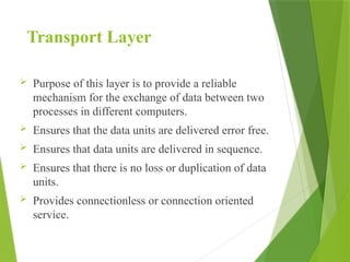
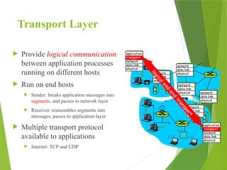
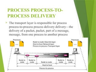
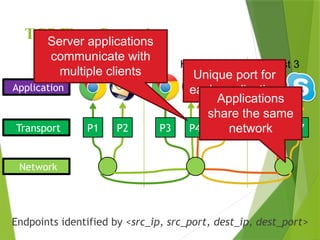
UNIT V
TRANSPORT LAYER
1
Transport Layer
 Purpose of this layer is to provide a reliable
mechanism for the exchange of data between two
processes in different computers.
 Ensures that the data units are delivered error free.
 Ensures that data units are delivered in sequence.
 Ensures that there is no loss or duplication of data
units.
 Provides connectionless or connection oriented
service.
Transport Layer
 Provide logical communication
between application processes
running on different hosts
 Run on end hosts
 Sender: breaks application messages into
segments, and passes to network layer
 Receiver: reassembles segments into
messages, passes to application layer
 Multiple transport protocol
available to applications
 Internet: TCP and UDP
application
transport
network
data link
physical
application
transport
network
data link
physical
network
data link
physical
network
data link
physical
network
data link
physical
network
data link
physical
network
data link
physical
l
o
g
i
c
a
l
e
n
d
-
e
n
d
t
r
a
n
s
p
o
r
t
Transport Layer
 Responsibility
 Process to process delivery
 End-to-end Connection between hosts
 Multiplexing and Demultiplexing
PROCESS PROCESS-TO-
PROCESS DELIVERY
 The transport layer is responsible for process
process-to-process process delivery delivery—the
delivery of a packet, packet, part of a message,
message, from one process to another process
PROCESS PROCESS-TO-
PROCESS DELIVERY
 Data Link Layer requires the MAC address of source-
destination hosts to correctly deliver a frame
 Network layer requires the IP address for appropriate routing
of packets
 In a similar way Transport Layer requires a Port number to
correctly deliver the segments of data to the correct process
amongst the multiple processes running on a particular host.
PROCESS PROCESS-TO-
PROCESS DELIVERY
PROCESS PROCESS-TO-
PROCESS DELIVERY
 Process-to-process delivery needs two identifiers, IP address
and the port number, at each end to make a connection.
 The combination of an IP address and a port number is called
a socket address.
 The client socket address defines the client process uniquely
just as the server socket address defines the server process
uniquely.
UDP: User Datagram Protocol
 In TCP/IP protocol suite, using IP to transport datagram
(similar to IP datagram).
 Allows a application to send datagram to other application on
the remote machine.
 Delivery and duplicate detection are not guaranteed.
UDP: Characteristics
 End-to-End: an application sends/receives data to/from
another application.
 Connectionless: Application does not need to pre-establish
communication before sending data; application does not
need to terminate communication when finished.
 Message-oriented: application sends/receives individual
messages (UDP datagram), not packets.
 Best-effort: same best-effort delivery semantics as IP. I.e.
message can be lost, duplicated, and corrupted.
 Arbitrary interaction: application communicates with many
or one other applications.
 Operating system independent: identifying application does
not depend on O/S
UDP: Datagram Format
 Source Port - 16 bit port number
 Destination Port - 16 bit port number.
 Length (of UDP header + data) - 16 bit count of octets
 UDP checksum - 16 bit field. if 0, then there is no checksum, else it
is a checksum over a pseudo header + UDP data area
 UDP uses a pseudo-header to verify that the UDP message has
arrived at both the correct machine and the correct port
UDP: Encapsulation and
Layering
 UDP message is encapsulated into an IP datagram
 IP datagram in turn is encapsulated into a physical frame for
actually delivery.
Transmission Control Protocol
(TCP)
 Connection oriented
 Explicit set-up and tear-down of TCP session
 Stream-of-bytes service
 Sends and receives a stream of bytes, not messages
 Reliable, in-order delivery
 Checksums to detect corrupted data
 Acknowledgments & retransmissions for reliable delivery
 Sequence numbers to detect losses and reorder data
 Flow control
 Prevent overflow of the receiver’s buffer space
 Congestion control
 Adapt to network congestion for the greater good
TCP: Reliable Delivery
 Acknowledgments from receiver
 Positive: “okay” or “ACK”
 Negative: “please repeat that” or “NACK”
 Timeout by the sender (“stop and wait”)
 Don’t wait indefinitely without receiving some response
 … whether a positive or a negative acknowledgment
 Retransmission by the sender
 After receiving a “NACK” from the receiver
 After receiving no feedback from the receiver
TCP: Reliable Delivery
 Checksum
 Used to detect corrupted data at the receiver
 …leading the receiver to drop the packet
 Sequence numbers
 Used to detect missing data
 ... and for putting the data back in order
 Retransmission
 Sender retransmits lost or corrupted data
 Timeout based on estimates of round-trip time
 Fast retransmit algorithm for rapid retransmission
TCP : Segment
S R
Send SYN Receive SYN
SYN_SEND Time out
SYN_RCV Time out
Receive SYN_ACK Send SYN_ACK
Send ACK Receive ACK
Connection
Established
Data Transfer
TCP Connection Established
S R
Send FIN Receive FIN
SYN_WAIT Time out
Receive ACK Send ACK
Receive FIN Send FIN
Close_wait Timeout
Close Time out
TCP Connection Terminate
Send ACK Receive ACK
TCP Segments
Byte
0
Byte
1
Byte
2
Byte
3
Byte
0
Byte
1
Byte
2
Byte
3
Host A
Host B
Byte
80
Byte
80
TCP Segments
Byte
0
Byte
1
Byte
2
Byte
3
Byte
0
Byte
1
Byte
2
Byte
3
Host A
Host B
Byte
80
TCP Data
TCP Data
Byte
80
Segment sent when:
1. Segment full (Max Segment Size),
2. Not full, but times out, or
3. “Pushed” by application.
TCP Segments
 IP packet
 No bigger than Maximum Transmission Unit (MTU)
 E.g., up to 1500 bytes on an Ethernet
 TCP packet
 IP packet with a TCP header and data inside
 TCP header is typically 20 bytes long
 TCP segment
 No more than Maximum Segment Size (MSS) bytes
 E.g., up to 1460 consecutive bytes from the stream
IP Hdr
IP Data
TCP Hdr
TCP Data (segment)
TCP: Initial Sequence Number
(ISN)
 Sequence number for the very first byte
 E.g., Why not ISN is 0?
 Practical issue
 IP addresses and port #s uniquely identify a connection
 Eventually, though, these port #s do get used again
 … and there is a chance an old packet is still in flight
 … and might be associated with the new connection
 So, TCP requires changing the ISN over time
 Set from a 32-bit clock that ticks every 4 microseconds
 … which only wraps around once every 4.55 hours!
 But, this means the hosts need to exchange ISN
TCP : Sequence Numbers
Host A
Host B
TCP Data TCP
HDR
ISN (initial sequence number)
Sequence
number = 1st
byte ACK sequence
number = next
expected byte
TCP Data TCP
HDR
TCP : Segment
TCP segment structure
S R
Send SYN Receive SYN
SYN_SEND Time
out
SYN_RCV Time out
Receive
SYN_ACK
Send
SYN_ACK
Send ACK Receive ACK
Connection
Established
Data Transfer
TCP Connection
Established
S R
Send FIN Receive FIN
SYN_WAIT Time
out
Receive
ACK Send ACK
Receive FIN Send FIN
Close_wait Timeout
Close Time out
TCP Connection
Terminate
Send ACK Receive ACK
TCP : Segment
TCP : three-way handshaking
Stream Control Transmission Protocol
Process-to-Process Communication
 Multiple Streams
 Multihoming
 Full-Duplex Communication
 Connection-Oriented Service
 Reliable Service
Message-oriented
Stream Control Transmission Protocol
 UDP: Message-oriented, Unreliable
 TCP: Byte-oriented, Reliable
 SCTP
 Message-oriented, Reliable
 Other innovative features
Association, Data transfer/Delivery
Fragmentation, Error/Congestion Control
Stream Control Transmission Protocol
Multiple Streams
If one of the streams is blocked,
the other streams can still deliver
their data.
Stream Control Transmission Protocol
Multi-Homing
 Two fundamental concepts in SCTP:
 Endpoints (communicating parties)
 Associations (communicating relationships)
 SCTP Associations allows multiple IP addresses for each end
point.
TCP Flow Control
Endpoints identified by <src_ip, src_port, dest_ip, dest_port>
Network
Transport
Application
P1 P2 P3 P4 P6 P7
P5
Host 1 Host 2 Host 3
Unique port for
each application
Applications
share the same
network
Server applications
communicate with
multiple clients
TCP Flow Control
 Receive side of TCP
connection has a receive
buffer:
 speed-matching
service: matching
the send rate to
the receiving
app’s drain rate
app process may be slow at
reading from buffer
sender won’t overflow
receiver’s buffer by
transmitting too
much,
too fast
flow control
TCP Flow Control
 Each side:
 Notifies the other of starting sequence number
 ACKs the other side’s starting sequence
number
Client Server
SYN <SeqC, 0>
SYN/ACK <SeqS, SeqC+1>
ACK <SeqC+1, SeqS+1>
Why
Sequence # +1?
 Important TCP flags (1 bit
each)
 SYN –
synchronization, used
for connection setup
 ACK – acknowledge
received data
 FIN – finish, used to
tear down connection
TCP Flow Control
 Either side can initiate tear
down
 Other side may continue
sending data
 Half open connection
 shutdown()
 Acknowledge the last FIN
 Sequence number + 1
 What happens if 2nd
FIN is
lost?
Client Server
FIN <SeqA, *>
ACK <*, SeqA+1>
ACK
Data
FIN <SeqB, *>
ACK <*, SeqB+1>
TCP Flow Control
 Each side of the connection can send and receive
 Different sequence numbers for each direction
Client Server
Data (1460 bytes)
Data/ACK (730 bytes)
Data/ACK (1460 bytes)
Seq. Ack. Seq. Ack.
1 23
23 1461
1461 753
753 2921
Data and ACK in
the same packet
23 1
TCP Flow Control
 Problem: how many packets should a sender transmit?
 Too many packets may overwhelm the receiver
 Size of the receivers buffers may change over time
 Solution: sliding window
 Receiver tells the sender how big their buffer is
 Called the advertised window
 For window size n, sender may transmit n bytes without receiving
an ACK
 After each ACK, the window slides forward
 Window may go to zero!
TCP Flow Control
Sequence Number
Src. Port
Acknowledgement Number
Window
Urgent Pointer
Flags
Checksum
HL
Packet Sent
Dest. Port
Src. Port
Acknowledgement Number
Window
Urgent Pointer
Flags
Checksum
HL
Packet Received
Dest. Port
Sequence Number
ACKed Sent To Be Sent Outside Window
Window
Must be buffered
until ACKed
TCP Flow Control
1
2
3
4
5
6
7
5
6
7
Time Time
TCP is ACK Clocked
• Short RTT  quick ACK  window slides quickly
• Long RTT  slow ACK  window slides slowly
TCP Flow Control
1. ACK every packet
2. Use cumulative ACK, where an ACK for sequence n
implies ACKS for all k < n
3. Use negative ACKs (NACKs), indicating which packet
did not arrive
4. Use selective ACKs (SACKs), indicating those that did
arrive, even if not in order
 SACK is an actual TCP extension
TCP Flow Control
 The bursty traffic in the network
results in congestion
 Traffic shaping reduces congestion
and thus helps the carrier live up to
its guarantees
 Traffic shaping is about regulating
the average rate (and burstiness) of
data transmission
TCP Flow Control
 Traffic shaping controls the rate at
which packets are sent (not just
how many)
 At connection set-up time, the
sender and carrier negotiate a
traffic pattern (shape)
 Two traffic shaping algorithms
are:
 Leaky Bucket
 Token Bucket
The Leaky Bucket Algorithm
 The Leaky Bucket Algorithm
used to control rate in a network.
It is implemented as a single-
server queue with constant service
time. If the bucket (buffer)
overflows then packets are
discarded.
The Leaky Bucket Algorithm
(a) A leaky bucket with water (b) a leaky bucket with packets.
The Leaky Bucket Algorithm
 The leaky bucket enforces a constant output
rate regardless of the burstiness of the input.
Does nothing when input is idle.
 The host injects one packet per clock tick onto
the network. This results in a uniform flow of
packets, smoothing out bursts and reducing
congestion.
 When packets are the same size, the one
packet per tick is okay. For variable length
packets though, it is better to allow a fixed
number of bytes per tick.
The Leaky Bucket Algorithm
 Step - 1 : Initialize the counter to ‘n’ at every
tick of clock.
 Step - 2 : If n is greater than the size of packet
in the front of queue send the packet into the
network and decrement the counter by size of
packet. Repeat the step until n is less than the
size of packet.
 Step - 3 : Reset the counter and go to Step - 1.
The Leaky Bucket Algorithm
 Let n = 1000
 Packet =. 200 700 500 450 400 200
 Since n > front of Queue i.e. n>200
Therefore, n= 1000-200 = 800
Packet size of 200 is sent to the network
 Packet=200 700 500 450 400
 Now Again n > front of queue i.e. n > 400
Therefore, n= 800-400 = 400
Packet size of 400 is sent to the network
 Packet=200 700 500 450
 Since n < front of queue .
 There fore, the procedure is stop. And we initialize n = 1000 on another
tick of clock.
 This procedure is repeated until all the packets is sent to the network.
Token Bucket Algorithm
 In contrast to the LB, the Token Bucket (TB)
algorithm, allows the output rate to vary,
depending on the size of the burst.
 In the TB algorithm, the bucket holds tokens.
To transmit a packet, the host must capture
and destroy one token.
 Tokens are generated by a clock at the rate of
one token every t sec.
 Idle hosts can capture and save up tokens (up
to the max. size of the bucket) in order to send
larger bursts later.
Token Bucket Algorithm
 TB accumulates fixed size tokens in a token
bucket
 Transmits a packet (from data buffer, if any are
there) or arriving packet if the sum of the token
sizes in the bucket add up to packet size
 More tokens are periodically added to the bucket
(at rate t). If tokens are to be added when the
bucket is full, they are discarded
 Does not bound the peak rate of small bursts,
because bucket may contain enough token to cover
a complete burst size
 Performance depends only on the sum of the data
buffer size and the token bucket size
Choke Packet
 Choke packets are used for congestion and flow
control over a network
 A choke packet is used in network maintenance
and quality management
 Use to inform a specific node or transmitter that its
transmitted traffic is creating congestion over the
network.
 This forces the node or transmitter to reduce its
output rate.
 he source node is addressed directly by the router,
forcing it to decrease its sending rate
 The source node acknowledges this by reducing
the sending rate by some percentage.
What is Congestion?
 Load on the network is higher than capacity
 Capacity is not uniform across networks
 Modem vs. Cellular vs. Cable vs. Fiber Optics
 There are multiple flows competing for bandwidth
 Residential cable modem vs. corporate datacenter
 Load is not uniform over time
 10pm, Saturday night = Heavy Load
Why is Congestion Bad?
 Results in packet loss
Routers have finite buffers
Internet traffic is self similar, no buffer can prevent all
drops
When routers get overloaded, packets will be dropped
 Practical consequences
Router queues build up, delay increases
Wasted bandwidth from retransmissions
Low network
The Danger of Increasing Load
 Knee – point after which
 Throughput increases very slow
 Delay increases fast
 In an M/M/1 queue
 Delay = 1/(1 – utilization)
 Cliff – point after which
 Throughput  0

Delay  ∞
Congestion
Collapse
Load
Load
Goodput
Delay
Knee Cliff
Ideal point
Cong. Control vs. Cong. Avoidance
Congestion
Collapse
Goodput
Knee Cliff
Load
Congestion Avoidance:
Stay left of the knee
Congestion Control:
Stay left of the cliff
Goals of Congestion Control
1. Adjusting to the bottleneck bandwidth
2. Adjusting to variations in bandwidth
3. Sharing bandwidth between flows
4. Maximizing throughput
General Approaches
 Do nothing, send packets indiscriminately
 Many packets will drop, totally unpredictable performance
 May lead to congestion collapse
 Reservations
 Pre-arrange bandwidth allocations for flows
 Requires negotiation before sending packets
 Must be supported by the network
 Dynamic adjustment
 Use probes to estimate level of congestion
 Speed up when congestion is low
 Slow down when congestion increases
 Messy dynamics, requires distributed coordination
TCP
MN
(S)
Internet Host MN
(R)
Internet
Transceiver Transceiver
Router Router
HA
FA
Home Network Foreign Network
I-TCP
 No changes to the TCP protocol for hosts connected to the
wired Internet, millions of computers use (variants of) this
protocol
 Optimized TCP protocol for mobile hosts
 Splitting of the TCP connection.
How does your mobile phone work
I-TCP
MN Internet Host MN
Internet
Wireless
Transceiver
Wireless
Transceiver
Router Router
HA
FA
Home Network Foreign Network
I-TCP
 No changes to the TCP protocol for hosts connected to the
wired Internet, millions of computers use (variants of) this
protocol
 optimized TCP protocol for mobile hosts
 Splitting of the TCP connection.
 Internet hosts in the fixed part of the net do not notice the
characteristics of the wireless part
I-TCP
 Advantage-
 Transmission errors on the wireless link do not propagate into the
fixed network
 Simple to control, mobile TCP is used only for one hop, between
a Foreign agent and a mobile host.
 Disadvantage-
 Loss of end-to-end semantics.
 Higher Latency
 High trust at foreign agent; end-to-end encryption impossible
Snooping TCP
 Buffering of packets sent to the mobile host.
 Lost packets on the wireless link (both directions!) will be
retransmitted immediately by the mobile host or foreign agent,
respectively (so called “local” retransmission).
 The foreign agent therefore “snoops” the packet flow and
recognizes acknowledgements in both directions, it also filters
ACKs.
 Changes of TCP only within the foreign agent
Snooping TCP
 Data transfer to the mobile host
 FA buffers data until it receives ACK of the
MH, FA detects packet loss via duplicated
ACKs or time-out.
 Fast retransmission possible, transparent for the
fixed network.
 Data transfer from the mobile host
 FA detects packet loss on the wireless link via
sequence numbers, FA answers directly with a
NACK to the MH.
 MH can now retransmit data with only a very
short delay.
M-TCP
 M-TCP splits as I-TCP does
 Unmodified TCP fixed network to
supervisory host (SH)
 Optimized TCP SH to MH
 Supervisory host
 No caching, No retransmission
 Monitors all packets, if disconnection
detects
 set sender window size to 0
 sender automatically goes into
persistent mode
 old or new SH reopen the window
M-TCP
 Advantage-
 Maintains semantics, supports disconnection, no buffer
forwarding
 Disadvantage-
 Loss on wireless link propagated into fixed network.
Fast retransmit/fast recovery
 As soon as the mobile host has registered with a new foreign agent,
the MH sends duplicated acknowledgements on purpose
Fast retransmit/fast recovery
 As soon as the mobile host has registered with a new foreign agent,
the MH sends duplicated acknowledgements on purpose
 This forces the fast retransmit mode at the communication partners
 The TCP on the MH is forced to continue sending with the Half-of-
window size and not to go into slow-start after registration
Fast retransmit/fast recovery
S R
X1
X2
X3
X3
X1’ X2
X3’X4
X4’X5
T1
T2
T3
X2’X3
X3’X4
X4
T4
T3
8
6
3
2
1
12
Transmission/time-out freezing
 TCP sends an acknowledgement only after receiving a packet.
 No packet exchange possible
 e.g., in a tunnel, disconnection due to overloaded cells or mux, with
higher priority traffic. This forces the fast retransmit mode at the
communication partners
 TCP disconnects after time-out completely
Transmission/time-out freezing
S R
X1
X2
X3
X4
X1’ X2
X3’X4
X4’X5
T1
T2
T4
T3
X2’X3
Transmission/time-out freezing
S R
X1
X2
X3
X4
X1’ X2
X3’X4
X4’X5
T1
T2
T4
T3
X2’X3
8
6
3
2
1
12
Transmission/time-out freezing
S R
X1
X2
X3
X3
X1’ X2
X3’X4
X4’X5
T1
T2
T3
X2’X3
X3’X4
X4
T4
T3
8
6
3
2
1
12
Transmission/time-out freezing
 If a sender receives several acknowledgements for the same packet, this is
due to a gap in received packets at the receiver
Transmission/time-out freezing
S R
X1
X2
X3
X3
X1’ X2
X3’X4
X4’X5
T1
T2
T3
X2’X3
X3’X4
X4
T4
T3
8
6
3
2
1
1
2
Transmission/time-out freezing
 If a sender receives several acknowledgements for the same packet, this is
due to a gap in received packets at the receiver
 Therefore, packet loss is not due to congestion, continue with current
congestion window
 DO NOT USE SLOW-START
Transmission/time-out freezing
 MAC layer is often able to detect interruption in advance
 MAC can inform TCP layer of upcoming loss of connection
 TCP stops sending, but does now not assume a congested link
 MAC layer signals again if reconnected
Selective retransmission
S R
X1
X2
X3
X4
X1’ X2
X3’X4 X2
X4’X5 X2
T1
T2
T4
T3
X2’X3
X2
T2
8
6
3
2
1
12
X1 X2 X3 X4 X5
Selective retransmission
S R
X1
X2
X3
X4
X1’ X2
X3’X4 X2
X4’X5 X2
T1
T2
T4
T3
X2’X3
X2
T2
8
6
3
2
1
1
2
X1 X2 X3 X4 X5 X2 X6
Selective retransmission
 ACK n acknowledges correct and in-sequence receipt of packets up
to n
 if single packets are missing quite often a whole packet sequence
beginning at the gap has to be retransmitted (go-back-n), thus
wasting bandwidth
 sender can now retransmit only the missing packets
Transaction oriented TCP
 ACK n acknowledges correct and in-sequence receipt of packets up
to n
 if single packets are missing quite often a whole packet sequence
beginning at the gap has to be retransmitted (go-back-n), thus
wasting bandwidth
 sender can now retransmit only the missing packets

Unit V computer network notes for study.

  • 1.
  • 2.
    Transport Layer  Purposeof this layer is to provide a reliable mechanism for the exchange of data between two processes in different computers.  Ensures that the data units are delivered error free.  Ensures that data units are delivered in sequence.  Ensures that there is no loss or duplication of data units.  Provides connectionless or connection oriented service.
  • 3.
    Transport Layer  Providelogical communication between application processes running on different hosts  Run on end hosts  Sender: breaks application messages into segments, and passes to network layer  Receiver: reassembles segments into messages, passes to application layer  Multiple transport protocol available to applications  Internet: TCP and UDP application transport network data link physical application transport network data link physical network data link physical network data link physical network data link physical network data link physical network data link physical l o g i c a l e n d - e n d t r a n s p o r t
  • 4.
    Transport Layer  Responsibility Process to process delivery  End-to-end Connection between hosts  Multiplexing and Demultiplexing
  • 5.
    PROCESS PROCESS-TO- PROCESS DELIVERY The transport layer is responsible for process process-to-process process delivery delivery—the delivery of a packet, packet, part of a message, message, from one process to another process
  • 6.
    PROCESS PROCESS-TO- PROCESS DELIVERY Data Link Layer requires the MAC address of source- destination hosts to correctly deliver a frame  Network layer requires the IP address for appropriate routing of packets  In a similar way Transport Layer requires a Port number to correctly deliver the segments of data to the correct process amongst the multiple processes running on a particular host.
  • 7.
  • 8.
    PROCESS PROCESS-TO- PROCESS DELIVERY Process-to-process delivery needs two identifiers, IP address and the port number, at each end to make a connection.  The combination of an IP address and a port number is called a socket address.  The client socket address defines the client process uniquely just as the server socket address defines the server process uniquely.
  • 9.
    UDP: User DatagramProtocol  In TCP/IP protocol suite, using IP to transport datagram (similar to IP datagram).  Allows a application to send datagram to other application on the remote machine.  Delivery and duplicate detection are not guaranteed.
  • 10.
    UDP: Characteristics  End-to-End:an application sends/receives data to/from another application.  Connectionless: Application does not need to pre-establish communication before sending data; application does not need to terminate communication when finished.  Message-oriented: application sends/receives individual messages (UDP datagram), not packets.  Best-effort: same best-effort delivery semantics as IP. I.e. message can be lost, duplicated, and corrupted.  Arbitrary interaction: application communicates with many or one other applications.  Operating system independent: identifying application does not depend on O/S
  • 11.
    UDP: Datagram Format Source Port - 16 bit port number  Destination Port - 16 bit port number.  Length (of UDP header + data) - 16 bit count of octets  UDP checksum - 16 bit field. if 0, then there is no checksum, else it is a checksum over a pseudo header + UDP data area  UDP uses a pseudo-header to verify that the UDP message has arrived at both the correct machine and the correct port
  • 12.
    UDP: Encapsulation and Layering UDP message is encapsulated into an IP datagram  IP datagram in turn is encapsulated into a physical frame for actually delivery.
  • 13.
    Transmission Control Protocol (TCP) Connection oriented  Explicit set-up and tear-down of TCP session  Stream-of-bytes service  Sends and receives a stream of bytes, not messages  Reliable, in-order delivery  Checksums to detect corrupted data  Acknowledgments & retransmissions for reliable delivery  Sequence numbers to detect losses and reorder data  Flow control  Prevent overflow of the receiver’s buffer space  Congestion control  Adapt to network congestion for the greater good
  • 14.
    TCP: Reliable Delivery Acknowledgments from receiver  Positive: “okay” or “ACK”  Negative: “please repeat that” or “NACK”  Timeout by the sender (“stop and wait”)  Don’t wait indefinitely without receiving some response  … whether a positive or a negative acknowledgment  Retransmission by the sender  After receiving a “NACK” from the receiver  After receiving no feedback from the receiver
  • 15.
    TCP: Reliable Delivery Checksum  Used to detect corrupted data at the receiver  …leading the receiver to drop the packet  Sequence numbers  Used to detect missing data  ... and for putting the data back in order  Retransmission  Sender retransmits lost or corrupted data  Timeout based on estimates of round-trip time  Fast retransmit algorithm for rapid retransmission
  • 16.
    TCP : Segment SR Send SYN Receive SYN SYN_SEND Time out SYN_RCV Time out Receive SYN_ACK Send SYN_ACK Send ACK Receive ACK Connection Established Data Transfer TCP Connection Established S R Send FIN Receive FIN SYN_WAIT Time out Receive ACK Send ACK Receive FIN Send FIN Close_wait Timeout Close Time out TCP Connection Terminate Send ACK Receive ACK
  • 17.
  • 18.
    TCP Segments Byte 0 Byte 1 Byte 2 Byte 3 Byte 0 Byte 1 Byte 2 Byte 3 Host A HostB Byte 80 TCP Data TCP Data Byte 80 Segment sent when: 1. Segment full (Max Segment Size), 2. Not full, but times out, or 3. “Pushed” by application.
  • 19.
    TCP Segments  IPpacket  No bigger than Maximum Transmission Unit (MTU)  E.g., up to 1500 bytes on an Ethernet  TCP packet  IP packet with a TCP header and data inside  TCP header is typically 20 bytes long  TCP segment  No more than Maximum Segment Size (MSS) bytes  E.g., up to 1460 consecutive bytes from the stream IP Hdr IP Data TCP Hdr TCP Data (segment)
  • 20.
    TCP: Initial SequenceNumber (ISN)  Sequence number for the very first byte  E.g., Why not ISN is 0?  Practical issue  IP addresses and port #s uniquely identify a connection  Eventually, though, these port #s do get used again  … and there is a chance an old packet is still in flight  … and might be associated with the new connection  So, TCP requires changing the ISN over time  Set from a 32-bit clock that ticks every 4 microseconds  … which only wraps around once every 4.55 hours!  But, this means the hosts need to exchange ISN
  • 21.
    TCP : SequenceNumbers Host A Host B TCP Data TCP HDR ISN (initial sequence number) Sequence number = 1st byte ACK sequence number = next expected byte TCP Data TCP HDR
  • 22.
  • 23.
    TCP segment structure SR Send SYN Receive SYN SYN_SEND Time out SYN_RCV Time out Receive SYN_ACK Send SYN_ACK Send ACK Receive ACK Connection Established Data Transfer TCP Connection Established S R Send FIN Receive FIN SYN_WAIT Time out Receive ACK Send ACK Receive FIN Send FIN Close_wait Timeout Close Time out TCP Connection Terminate Send ACK Receive ACK
  • 24.
  • 25.
    TCP : three-wayhandshaking
  • 26.
    Stream Control TransmissionProtocol Process-to-Process Communication  Multiple Streams  Multihoming  Full-Duplex Communication  Connection-Oriented Service  Reliable Service Message-oriented
  • 27.
    Stream Control TransmissionProtocol  UDP: Message-oriented, Unreliable  TCP: Byte-oriented, Reliable  SCTP  Message-oriented, Reliable  Other innovative features Association, Data transfer/Delivery Fragmentation, Error/Congestion Control
  • 28.
    Stream Control TransmissionProtocol Multiple Streams If one of the streams is blocked, the other streams can still deliver their data.
  • 29.
    Stream Control TransmissionProtocol Multi-Homing  Two fundamental concepts in SCTP:  Endpoints (communicating parties)  Associations (communicating relationships)  SCTP Associations allows multiple IP addresses for each end point.
  • 30.
    TCP Flow Control Endpointsidentified by <src_ip, src_port, dest_ip, dest_port> Network Transport Application P1 P2 P3 P4 P6 P7 P5 Host 1 Host 2 Host 3 Unique port for each application Applications share the same network Server applications communicate with multiple clients
  • 31.
    TCP Flow Control Receive side of TCP connection has a receive buffer:  speed-matching service: matching the send rate to the receiving app’s drain rate app process may be slow at reading from buffer sender won’t overflow receiver’s buffer by transmitting too much, too fast flow control
  • 32.
    TCP Flow Control Each side:  Notifies the other of starting sequence number  ACKs the other side’s starting sequence number Client Server SYN <SeqC, 0> SYN/ACK <SeqS, SeqC+1> ACK <SeqC+1, SeqS+1> Why Sequence # +1?  Important TCP flags (1 bit each)  SYN – synchronization, used for connection setup  ACK – acknowledge received data  FIN – finish, used to tear down connection
  • 33.
    TCP Flow Control Either side can initiate tear down  Other side may continue sending data  Half open connection  shutdown()  Acknowledge the last FIN  Sequence number + 1  What happens if 2nd FIN is lost? Client Server FIN <SeqA, *> ACK <*, SeqA+1> ACK Data FIN <SeqB, *> ACK <*, SeqB+1>
  • 34.
    TCP Flow Control Each side of the connection can send and receive  Different sequence numbers for each direction Client Server Data (1460 bytes) Data/ACK (730 bytes) Data/ACK (1460 bytes) Seq. Ack. Seq. Ack. 1 23 23 1461 1461 753 753 2921 Data and ACK in the same packet 23 1
  • 35.
    TCP Flow Control Problem: how many packets should a sender transmit?  Too many packets may overwhelm the receiver  Size of the receivers buffers may change over time  Solution: sliding window  Receiver tells the sender how big their buffer is  Called the advertised window  For window size n, sender may transmit n bytes without receiving an ACK  After each ACK, the window slides forward  Window may go to zero!
  • 36.
    TCP Flow Control SequenceNumber Src. Port Acknowledgement Number Window Urgent Pointer Flags Checksum HL Packet Sent Dest. Port Src. Port Acknowledgement Number Window Urgent Pointer Flags Checksum HL Packet Received Dest. Port Sequence Number ACKed Sent To Be Sent Outside Window Window Must be buffered until ACKed
  • 37.
    TCP Flow Control 1 2 3 4 5 6 7 5 6 7 TimeTime TCP is ACK Clocked • Short RTT  quick ACK  window slides quickly • Long RTT  slow ACK  window slides slowly
  • 38.
    TCP Flow Control 1.ACK every packet 2. Use cumulative ACK, where an ACK for sequence n implies ACKS for all k < n 3. Use negative ACKs (NACKs), indicating which packet did not arrive 4. Use selective ACKs (SACKs), indicating those that did arrive, even if not in order  SACK is an actual TCP extension
  • 39.
    TCP Flow Control The bursty traffic in the network results in congestion  Traffic shaping reduces congestion and thus helps the carrier live up to its guarantees  Traffic shaping is about regulating the average rate (and burstiness) of data transmission
  • 40.
    TCP Flow Control Traffic shaping controls the rate at which packets are sent (not just how many)  At connection set-up time, the sender and carrier negotiate a traffic pattern (shape)  Two traffic shaping algorithms are:  Leaky Bucket  Token Bucket
  • 41.
    The Leaky BucketAlgorithm  The Leaky Bucket Algorithm used to control rate in a network. It is implemented as a single- server queue with constant service time. If the bucket (buffer) overflows then packets are discarded.
  • 42.
    The Leaky BucketAlgorithm (a) A leaky bucket with water (b) a leaky bucket with packets.
  • 43.
    The Leaky BucketAlgorithm  The leaky bucket enforces a constant output rate regardless of the burstiness of the input. Does nothing when input is idle.  The host injects one packet per clock tick onto the network. This results in a uniform flow of packets, smoothing out bursts and reducing congestion.  When packets are the same size, the one packet per tick is okay. For variable length packets though, it is better to allow a fixed number of bytes per tick.
  • 44.
    The Leaky BucketAlgorithm  Step - 1 : Initialize the counter to ‘n’ at every tick of clock.  Step - 2 : If n is greater than the size of packet in the front of queue send the packet into the network and decrement the counter by size of packet. Repeat the step until n is less than the size of packet.  Step - 3 : Reset the counter and go to Step - 1.
  • 45.
    The Leaky BucketAlgorithm  Let n = 1000  Packet =. 200 700 500 450 400 200  Since n > front of Queue i.e. n>200 Therefore, n= 1000-200 = 800 Packet size of 200 is sent to the network  Packet=200 700 500 450 400  Now Again n > front of queue i.e. n > 400 Therefore, n= 800-400 = 400 Packet size of 400 is sent to the network  Packet=200 700 500 450  Since n < front of queue .  There fore, the procedure is stop. And we initialize n = 1000 on another tick of clock.  This procedure is repeated until all the packets is sent to the network.
  • 46.
    Token Bucket Algorithm In contrast to the LB, the Token Bucket (TB) algorithm, allows the output rate to vary, depending on the size of the burst.  In the TB algorithm, the bucket holds tokens. To transmit a packet, the host must capture and destroy one token.  Tokens are generated by a clock at the rate of one token every t sec.  Idle hosts can capture and save up tokens (up to the max. size of the bucket) in order to send larger bursts later.
  • 47.
  • 48.
    Token Bucket Algorithm TB accumulates fixed size tokens in a token bucket  Transmits a packet (from data buffer, if any are there) or arriving packet if the sum of the token sizes in the bucket add up to packet size  More tokens are periodically added to the bucket (at rate t). If tokens are to be added when the bucket is full, they are discarded  Does not bound the peak rate of small bursts, because bucket may contain enough token to cover a complete burst size  Performance depends only on the sum of the data buffer size and the token bucket size
  • 49.
    Choke Packet  Chokepackets are used for congestion and flow control over a network  A choke packet is used in network maintenance and quality management  Use to inform a specific node or transmitter that its transmitted traffic is creating congestion over the network.  This forces the node or transmitter to reduce its output rate.  he source node is addressed directly by the router, forcing it to decrease its sending rate  The source node acknowledges this by reducing the sending rate by some percentage.
  • 50.
    What is Congestion? Load on the network is higher than capacity  Capacity is not uniform across networks  Modem vs. Cellular vs. Cable vs. Fiber Optics  There are multiple flows competing for bandwidth  Residential cable modem vs. corporate datacenter  Load is not uniform over time  10pm, Saturday night = Heavy Load
  • 51.
    Why is CongestionBad?  Results in packet loss Routers have finite buffers Internet traffic is self similar, no buffer can prevent all drops When routers get overloaded, packets will be dropped  Practical consequences Router queues build up, delay increases Wasted bandwidth from retransmissions Low network
  • 52.
    The Danger ofIncreasing Load  Knee – point after which  Throughput increases very slow  Delay increases fast  In an M/M/1 queue  Delay = 1/(1 – utilization)  Cliff – point after which  Throughput  0  Delay  ∞ Congestion Collapse Load Load Goodput Delay Knee Cliff Ideal point
  • 53.
    Cong. Control vs.Cong. Avoidance Congestion Collapse Goodput Knee Cliff Load Congestion Avoidance: Stay left of the knee Congestion Control: Stay left of the cliff
  • 54.
    Goals of CongestionControl 1. Adjusting to the bottleneck bandwidth 2. Adjusting to variations in bandwidth 3. Sharing bandwidth between flows 4. Maximizing throughput
  • 55.
    General Approaches  Donothing, send packets indiscriminately  Many packets will drop, totally unpredictable performance  May lead to congestion collapse  Reservations  Pre-arrange bandwidth allocations for flows  Requires negotiation before sending packets  Must be supported by the network  Dynamic adjustment  Use probes to estimate level of congestion  Speed up when congestion is low  Slow down when congestion increases  Messy dynamics, requires distributed coordination
  • 56.
    TCP MN (S) Internet Host MN (R) Internet TransceiverTransceiver Router Router HA FA Home Network Foreign Network
  • 57.
    I-TCP  No changesto the TCP protocol for hosts connected to the wired Internet, millions of computers use (variants of) this protocol  Optimized TCP protocol for mobile hosts  Splitting of the TCP connection. How does your mobile phone work
  • 58.
    I-TCP MN Internet HostMN Internet Wireless Transceiver Wireless Transceiver Router Router HA FA Home Network Foreign Network
  • 59.
    I-TCP  No changesto the TCP protocol for hosts connected to the wired Internet, millions of computers use (variants of) this protocol  optimized TCP protocol for mobile hosts  Splitting of the TCP connection.  Internet hosts in the fixed part of the net do not notice the characteristics of the wireless part
  • 60.
    I-TCP  Advantage-  Transmissionerrors on the wireless link do not propagate into the fixed network  Simple to control, mobile TCP is used only for one hop, between a Foreign agent and a mobile host.  Disadvantage-  Loss of end-to-end semantics.  Higher Latency  High trust at foreign agent; end-to-end encryption impossible
  • 61.
    Snooping TCP  Bufferingof packets sent to the mobile host.  Lost packets on the wireless link (both directions!) will be retransmitted immediately by the mobile host or foreign agent, respectively (so called “local” retransmission).  The foreign agent therefore “snoops” the packet flow and recognizes acknowledgements in both directions, it also filters ACKs.  Changes of TCP only within the foreign agent
  • 62.
    Snooping TCP  Datatransfer to the mobile host  FA buffers data until it receives ACK of the MH, FA detects packet loss via duplicated ACKs or time-out.  Fast retransmission possible, transparent for the fixed network.  Data transfer from the mobile host  FA detects packet loss on the wireless link via sequence numbers, FA answers directly with a NACK to the MH.  MH can now retransmit data with only a very short delay.
  • 63.
    M-TCP  M-TCP splitsas I-TCP does  Unmodified TCP fixed network to supervisory host (SH)  Optimized TCP SH to MH  Supervisory host  No caching, No retransmission  Monitors all packets, if disconnection detects  set sender window size to 0  sender automatically goes into persistent mode  old or new SH reopen the window
  • 64.
    M-TCP  Advantage-  Maintainssemantics, supports disconnection, no buffer forwarding  Disadvantage-  Loss on wireless link propagated into fixed network.
  • 65.
    Fast retransmit/fast recovery As soon as the mobile host has registered with a new foreign agent, the MH sends duplicated acknowledgements on purpose
  • 66.
    Fast retransmit/fast recovery As soon as the mobile host has registered with a new foreign agent, the MH sends duplicated acknowledgements on purpose  This forces the fast retransmit mode at the communication partners  The TCP on the MH is forced to continue sending with the Half-of- window size and not to go into slow-start after registration
  • 67.
    Fast retransmit/fast recovery SR X1 X2 X3 X3 X1’ X2 X3’X4 X4’X5 T1 T2 T3 X2’X3 X3’X4 X4 T4 T3 8 6 3 2 1 12
  • 68.
    Transmission/time-out freezing  TCPsends an acknowledgement only after receiving a packet.  No packet exchange possible  e.g., in a tunnel, disconnection due to overloaded cells or mux, with higher priority traffic. This forces the fast retransmit mode at the communication partners  TCP disconnects after time-out completely
  • 69.
    Transmission/time-out freezing S R X1 X2 X3 X4 X1’X2 X3’X4 X4’X5 T1 T2 T4 T3 X2’X3
  • 70.
    Transmission/time-out freezing S R X1 X2 X3 X4 X1’X2 X3’X4 X4’X5 T1 T2 T4 T3 X2’X3 8 6 3 2 1 12
  • 71.
    Transmission/time-out freezing S R X1 X2 X3 X3 X1’X2 X3’X4 X4’X5 T1 T2 T3 X2’X3 X3’X4 X4 T4 T3 8 6 3 2 1 12
  • 72.
    Transmission/time-out freezing  Ifa sender receives several acknowledgements for the same packet, this is due to a gap in received packets at the receiver
  • 73.
    Transmission/time-out freezing S R X1 X2 X3 X3 X1’X2 X3’X4 X4’X5 T1 T2 T3 X2’X3 X3’X4 X4 T4 T3 8 6 3 2 1 1 2
  • 74.
    Transmission/time-out freezing  Ifa sender receives several acknowledgements for the same packet, this is due to a gap in received packets at the receiver  Therefore, packet loss is not due to congestion, continue with current congestion window  DO NOT USE SLOW-START
  • 75.
    Transmission/time-out freezing  MAClayer is often able to detect interruption in advance  MAC can inform TCP layer of upcoming loss of connection  TCP stops sending, but does now not assume a congested link  MAC layer signals again if reconnected
  • 76.
    Selective retransmission S R X1 X2 X3 X4 X1’X2 X3’X4 X2 X4’X5 X2 T1 T2 T4 T3 X2’X3 X2 T2 8 6 3 2 1 12 X1 X2 X3 X4 X5
  • 77.
    Selective retransmission S R X1 X2 X3 X4 X1’X2 X3’X4 X2 X4’X5 X2 T1 T2 T4 T3 X2’X3 X2 T2 8 6 3 2 1 1 2 X1 X2 X3 X4 X5 X2 X6
  • 78.
    Selective retransmission  ACKn acknowledges correct and in-sequence receipt of packets up to n  if single packets are missing quite often a whole packet sequence beginning at the gap has to be retransmitted (go-back-n), thus wasting bandwidth  sender can now retransmit only the missing packets
  • 79.
    Transaction oriented TCP ACK n acknowledges correct and in-sequence receipt of packets up to n  if single packets are missing quite often a whole packet sequence beginning at the gap has to be retransmitted (go-back-n), thus wasting bandwidth  sender can now retransmit only the missing packets