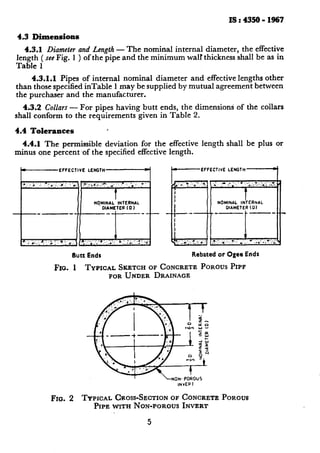
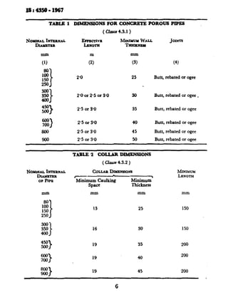
This document provides the specifications for concrete porous pipes used for under drainage. It outlines the materials, shapes and dimensions, manufacturing requirements, and testing procedures for such pipes. Key points include:
- Cement must conform to Indian Standards IS 269 or IS 455, or high alumina cement if required. Aggregates must pass a 20mm sieve and be retained on a 4.75mm sieve.
- Pipes can have uniform diameters and thicknesses with butt ends, or rebated/ogee ends for joints. Dimensions and tolerances are provided in tables.
- Manufacturing must result in accurate dimensions. Non-porous inverts may be included.
- Tests include a load
This document outlines specifications for precast concrete coping blocks. It specifies requirements for materials used in manufacturing coping blocks such as cement, aggregates, additives, and concrete strength. It also provides dimensions and tolerances for the cross-section and length of coping blocks. The specifications are intended to ensure coping blocks effectively prevent water penetration, direct water away from walls, resist displacement forces, allow for movement, and provide durability.
This document provides the specification for reinforced concrete fence posts according to Indian Standard IS:4996-1984. It outlines the materials, manufacturing process, shape and dimensions, and fixing of fencing wires for reinforced concrete fence posts. Some key points include:
- Cement, water, aggregates and reinforcement materials must meet standards specified.
- Posts are to be manufactured through mixing, placing and compacting concrete to be dense and free of voids.
- Reinforcement is to be properly positioned and anchored with minimum concrete cover requirements.
- Posts must cure for a minimum of 7 days and achieve a strength threshold before handling.
- Dimensions and tolerances are provided, with recommendations for line, strainer
This document is the Indian Standard specification for coarse and fine aggregates from natural sources for use in concrete. It outlines the requirements and limits for quality parameters like deleterious materials, aggregate crushing value, impact value, abrasion value and soundness. It defines terms related to aggregates and specifies four grading zones for fine aggregates of progressively finer sizes. The standard is intended to cover aggregates commonly available in India for general structural and mass concrete construction.
This document is the Indian Standard Specification for Mild Steel and Medium Tensile Steel Bars and Hard-Drawn Steel Wire for Concrete Reinforcement. It outlines requirements for mild steel and medium tensile steel reinforcement bars in round and square sections. The standard covers physical and mechanical properties of the bars, methods for testing, welding requirements, and provides definitions for key terminology. It aims to standardize specifications for reinforcement bars used in concrete structures in India.
This document outlines specifications for reinforced concrete dust bins in India, including:
- Dimensions and reinforcement requirements for circular and square bins of various sizes
- Minimum concrete thicknesses and reinforcement based on bin size
- Door, lid, and drainage hole requirements
- Marking information to be included on each bin
The specifications are intended to standardize dust bin construction across municipalities and organizations in India. Precise dimensions, materials, and construction details are provided to guide manufacturers.
This document provides standards for testing the strength of concrete in India. It outlines procedures for making and curing compression test specimens in a laboratory setting, including sampling materials, mixing, compacting, and curing the concrete specimens. It specifies that test specimens should be 150mm cubes or 150mm diameter cylinders for compressive strength testing. The document also references other Indian standards for materials used in concrete like cement, aggregates, and sieves.
This document provides guidelines for designing foundations for rotary machines of low frequency (below 1,500 rpm), such as crushers, pumps, motor generators, compressors, and rolling mill stands. It discusses typical foundation designs for a crushing mill, primary air fan, and instrument air compressor. The document also lists necessary data that should be obtained from machine manufacturers, such as mass, loading points, anchor bolt details, speeds, and unbalanced forces. Foundation design requires coordination between different engineering disciplines to achieve satisfactory performance, operation, economy, and appearance.
This document is the Indian Standard Specification for Concrete Masonry Units Part I: Hollow and Solid Concrete Blocks. It outlines specifications for the production of hollow and solid concrete blocks used in load-bearing and non-load-bearing walls. The standard specifies dimensions, tolerances, classifications based on density and compressive strength, and physical properties for the blocks. It provides requirements for hollow and solid concrete blocks to ensure quality, durability and structural integrity in masonry construction.
This document provides the standard test method for evaluating the performance of screed board concrete vibrators by measuring their ability to compact concrete. The test involves vibrating a 180mm thick concrete slab with a vibrator and taking density measurements from cores cut from the slab. If the density from each core is at least 93% of the maximum theoretical density, the vibrator passes the test. This direct measurement of compaction achieved provides a better assessment of a vibrator's quality than indirect measurements of vibration characteristics alone.
This document provides the code of practice for external cement concrete facings (Part II). It outlines the necessary information, materials, design considerations, and types of facings and attachment methods for concrete facing work. Some key points include:
- Precast concrete facing blocks must conform to IS 2185-1962 and have special treatment for durability, color, and surface texture. Common facing slab size is 60x40x3 cm.
- Materials for cramps and metal angle supports must resist corrosion. Mortar materials include cement, sand, lime, and surkhi.
- Structural design must consider wind loads per IS 875-1964 and stresses from facing weight.
- There are two
This document provides unit weights for various building materials and stored materials. It contains 3 tables: Table 1 lists unit weights of individual building materials alphabetically, ranging from acoustical materials to timber. Table 2 lists unit weights of building parts/components such as ceilings, floors, and walls. The Appendix lists unit weights of stored materials including agricultural products, chemicals, fuels, metals and textiles. The document aims to provide weight information to aid in structural design calculations for dead loads in buildings.
This document provides the specification for precast reinforced concrete door and window frames. It outlines the requirements for the shape and dimensions of frames, acceptable materials, manufacturing process, and curing. Frames can be single-piece or assembled from separate vertical and horizontal members. Reinforcement is required and specifications are provided for concrete mix design, aggregates, and curing. Tolerances and options for decorative finishes are also included. The specification is intended to provide guidance for manufacturers and users of precast concrete door and window frames.
This document provides standards for hollow and solid lightweight concrete blocks used in construction. It specifies:
1) Two grades (A and B) for load-bearing blocks based on intended use and weather protection.
2) Nominal dimensions for blocks ranging from 100-600mm in length, 50-300mm in width, and 100-200mm in height.
3) Tolerances of +/-5mm for length and +/-3mm for height and width.
4) Requirements for block density, compressive strength, water absorption, and drying shrinkage that vary based on grade.
This document provides the code of practice for constructing hollow concrete block masonry walls in India. It outlines the materials used such as hollow concrete blocks, cement, lime, sand and water. It provides specifications for mortar mixes and concrete fills. It also covers design considerations such as the thickness of load-bearing versus non-load-bearing walls. The code is intended to guide builders on the proper construction techniques and details to ensure successful performance of hollow concrete block masonry.
This document provides guidelines for the preparation and use of lime-pozzolana mixture concrete in buildings and roads. It discusses recommended mix proportions, materials, design considerations, strength characteristics, and preparation methods. Lime-pozzolana concrete has desirable properties such as low shrinkage, good workability, durability, and bond strength comparable to lean cement concrete. It can be used in foundations, floors, roofs, blocks, and as a base layer in composite road pavements. Compressive strength requirements vary from 1-4 MPa depending on the application.
This document provides guidelines for laying in-situ cement concrete flooring, including different types of floor finishes and their recommended thicknesses. It discusses monolithic and bonded floor finishes, noting that monolithic finishes provide better bonding but can be more difficult to construct and repair. It also outlines important considerations for materials, mix design, and construction methods to ensure satisfactory performance of cement concrete flooring.
This document is the Indian Standard Code of Practice for Plain and Reinforced Concrete. It provides guidelines for the design, materials, construction and quality control of concrete structures. The summary highlights:
1) This is the fourth revision of the standard which was originally published in 1953 and revised in 1957, 1964, and 1978.
2) Major changes in this revision include expanded guidance on durability design, simplified acceptance criteria aligned with international standards, and additional concrete grades and exposure conditions.
3) The revision aims to keep up with developments in concrete technology and incorporate improvements based on experience using earlier versions.
This document provides information about ready-mix concrete from an educational presentation. It introduces the topic and defines ready-mix concrete. It then discusses the main ingredients of concrete - cement, sand, coarse aggregate, water and admixtures - describing each in more detail. The document also covers the manufacturing process of ready-mix concrete, advantages, status and challenges in India, as well as some common quality problems and their causes.
This document summarizes a research study on strengthening reinforced concrete one-way slabs. It tested 21 slab specimens with different strengthening schemes including concrete overlay with various thicknesses and strengths, as well as the addition of carbon fiber reinforced polymer sheets. The experimental results showed that thicker and stronger concrete overlays increased cracking and ultimate loads compared to control specimens. Using bonding materials between the old and new concrete further improved load capacity. The best performing specimens combined a concrete overlay with externally bonded CFRP sheets, increasing ultimate load by 164% compared to controls.
This document is the Indian Standard for prestressed concrete pipes and specials. It specifies requirements for materials, dimensions, design criteria, and testing of prestressed concrete cylinder pipes and non-cylinder pipes. The standard covers pipes with nominal diameters between 200-2500 mm. It provides definitions of key terms, references other standards, and outlines design considerations and permissible stress limits for the longitudinal and circumferential prestressing of non-cylinder pressure pipes.
Punching Shear Strength of High Strength Fibre Reinforced Concrete SlabsIJMER
The experimental study of punching shear behavior of High Strength fiber reinforced
concrete slabs is carried out in the present work. Each of 24 square slabs was simply supported along
four edges and loaded to failure under a concentrated load over a square area at the center. The test
parameters were the effective span to depth aid ratio, volume fraction of 3 types of steel fibers, slab
thickness h, concrete strength fck, and size of load-bearing plate r. Test results indicate that the load
Flexural characteristics of sfrscc and sfrnc one way slabseSAT Journals
Abstract Fibre reinforced concrete with steel fibres attracted the attention of engineers and researchers during the last five decades. In recent times self-compacting concrete has been accepted as a quality product and are widely used. A large number of studies are available with respect to several parameters viz., load deflection behavior, toughness, flexural strength, ductility, effects of beam dimensions, concrete filling sequence, flexural toughness parameters, crack control etc. of fibre Reinforced Concrete. The present study aims to study the flexural behavior of SFRSCC and SFRNC slabs with steel fibres. Keywords: Self compacting concrete1, Fibre reinforced concrete2, Steel fibre reinforce normal concrete3, Steel fibre reinforce4, Self-compacting concrete5.
IJRET : International Journal of Research in Engineering and Technology is an international peer reviewed, online journal published by eSAT Publishing House for the enhancement of research in various disciplines of Engineering and Technology. The aim and scope of the journal is to provide an academic medium and an important reference for the advancement and dissemination of research results that support high-level learning, teaching and research in the fields of Engineering and Technology. We bring together Scientists, Academician, Field Engineers, Scholars and Students of related fields of Engineering and Technology.
This document summarizes a research study on the characteristics of concrete with partial replacements of cement with fly ash and rice husk ash. The study aimed to evaluate the compressive, tensile, and flexural strengths of concrete mixes containing varying percentages of fly ash and rice husk ash, both individually and combined, as a replacement for cement. The results showed that compressive strength increased up to a 12% replacement of cement with fly ash or rice husk ash. Combining the two ash materials in concrete generally resulted in lower strengths compared to the individual ash mixes. The study concluded that rice husk ash and fly ash can be effectively used to partially replace cement in concrete to improve properties and reduce costs.
This document provides specifications for precast concrete kerbs, channels, edgings, quadrants, and gutter aprons. It outlines materials requirements including cement, aggregates, and concrete strength. It describes standard section dimensions and tolerances. Finish and color can be specified by the purchaser, with natural being default. The document aims to incorporate revisions from updated related standards to align with current Indian precast concrete industry practices.
Experimental Evaluation of Metal Composite Multi Bolt Radial Joint on Laminat...IJERA Editor
Longitudinal tensile load exerted due to internal hydraulic pressure, on bolted radial joints between large size PAN carbon epoxy filament wound composite cylindrical section and small size 15CDV6 steel cylindrical sections, were simulated and tested on flat laminate level, mainly to check the strength of PAN carbon epoxy helical wound laminate made by wet winding method. Small segmental portion of circumference of cylindrical sections was considered as width of composite laminate and of metallic plates, necessary to accommodate 5 rows of fasteners in transverse direction with specified pitch distance. Bolted radial joints between carbon epoxy helical wound flat laminate and 15CDV6 steel plates were realized with 8 numbers of steel fasteners distributed in 3 longitudinal and 5 transverse rows at each joint. Helical angle of winding, length and thickness of carbon epoxy laminate was ±22.5°, 458mm and 11mm respectively. Length and structural thickness of radial joints, total length and width of assembly test specimen were 98mm, 18mm, 870mm and 169.43mm respectively. Joints were tested under uni-axial tensile load up to failure. Joints failed at 18 tonnes (1.7 times of design load). Failure mode was observed as initiation of bearing failure at all 8, countersink fastener holes in laminate and shear out failure at edge hole. Strains in fibre direction, at 45°and at transverse to fibre direction were found very less. Maximum compressive strain and residual strain, near fastener holes were found as -1423 and -136 micro strain respectively. Test was successful.
This document provides the specifications for precast reinforced concrete street lighting poles. It outlines the materials, design considerations, testing requirements and more. Some key points:
- Poles must be a minimum of 5.2m in length, with mounting heights of at least 4m and planting depths of at least 1.2m.
- Concrete grade shall be at minimum M20. Reinforcement can be mild steel, medium tensile steel or deformed steel bars.
- Poles shall be designed to resist a maximum bending moment from loads like wind pressure and the weight of fixtures applied 600mm below the light source.
- Testing includes determining the ultimate transverse load at which the pole fails under a load
The document provides specifications for precast prestressed concrete street lighting poles. It outlines requirements for materials, design, testing, and other technical details. Key points include:
- It specifies requirements for cement, aggregates, reinforcement, concrete, and admixtures to be used in manufacturing the poles.
- Design specifications include minimum pole length, depth of planting, distances from luminaire to light source, and standard outreach lengths. Poles must be designed not to fail due to compression of concrete.
- Technical details covered include tolerances on dimensions, sampling and inspection procedures, marking requirements, and other quality control aspects.
This document is the Indian Standard specification for coarse and fine aggregates from natural sources for use in concrete. It outlines various requirements for aggregates including limits on deleterious materials, aggregate crushing value, impact value, abrasion value, and soundness. It defines terms related to aggregates and specifies four grading zones for fine aggregates of different particle sizes. The standard is intended to ensure aggregates are suitable for producing durable concrete structures.
This document provides specifications for hard-drawn steel wire fabric used for concrete reinforcement. It defines key terms, specifies the material and manufacturing requirements, and sets tolerances. There are two types of fabric - oblong and square mesh. Dimensions include mesh size, weight, and wire diameters. Sheets and rolls have specified widths and lengths to fit construction modules. Mass is calculated based on the steel density, and actual mass is determined by weighing samples.
This document provides a code of practice for the construction of autoclaved cellular concrete block masonry. It outlines materials and design considerations for constructing load-bearing and non-load bearing walls using these blocks. The document discusses block requirements, mortar mixes, wall thickness, bracing, and modular coordination. It aims to help builders properly use this type of masonry and ensure structural safety and avoidance of cracks.
This document provides specifications for precast concrete cable covers. It classifies cable covers based on whether they are reinforced or unreinforced, and whether they have a peaked or flat design. Reinforced concrete covers with a peaked design are recommended for high voltage cables of 22kV and above. Unreinforced peaked covers are for voltages above 1kV but below 22kV. Unreinforced flat covers are used for cables up to and including 1kV. The document specifies requirements for materials, dimensions, reinforcement, and markings for the different types and classes of precast concrete cable covers.
This document provides a code of practice for laying concrete pipes. It includes methods for calculating loads on pipes according to installation conditions and provides corresponding load factors. The purpose is to relate the loads on concrete pipes installed under various conditions to the test strength of the pipe, through appropriate load factors. The document defines key terms, outlines symbols used in calculations, and describes methods to calculate vertical loads on pipes from earth fill material, concentrated loads, and distributed loads. It is intended to be used with other standards for concrete pipes to help ensure pipes are not subjected to loads exceeding their design strength.
This document provides the specification for concrete masonry units including hollow and solid concrete blocks. It defines key terms, specifies dimensions and tolerances for blocks, and classifies blocks into different grades based on their density and compressive strength. The standard aims to promote the use of concrete masonry in construction by specifying requirements for different types of blocks to allow for load-bearing and non-load-bearing walls as well as other applications.
The document provides specifications for an apparatus used to measure the length change of hardened cement paste, mortar, and concrete. It describes the construction, dimensions, materials, and markings required for a length comparator, which uses a micrometer to measure the change in length of specimens against a reference bar. The length comparator consists of an adjustable frame that holds either a screw or dial micrometer and allows measurement of specimens of different lengths.
This document provides the specification for cement concrete flooring tiles in India. It outlines the various types of tiles covered (plain cement, plain colored, terrazzo), classes based on duty (general purpose, heavy duty), materials used, dimensions, tolerances, testing methods, and other quality requirements. The revision updates certain provisions based on experience and comments received, including allowing a larger wearing layer thickness and modifying the abrasion resistance test method. It aims to improve quality while keeping requirements relevant to indigenous manufacturers.
This document provides specifications for concrete vibrating tables. It outlines requirements for materials, design, size, capacity and motive power of vibrating tables. Tables are designated by their length and breadth in meters and have minimum capacities of 0.5, 1 or 1.5 tonnes depending on their size. Materials must meet relevant Indian standards and tables can be powered by an eccentric rotor, engine, pneumatic power or electromagnetic pulsators. The document establishes performance testing methods and ensures tables effectively compact concrete in molds.
This document provides the standard method for testing the permeability of cement mortar and concrete specimens. It outlines the necessary apparatus, including a permeability cell and water reservoir. It describes how to prepare and seal cylindrical specimens for testing. The standard test pressure is 10 kg/cm2, but may be reduced to 5 kg/cm2 or increased to 15 kg/cm2 depending on the permeability of the specimen. The test involves applying pressure to one side of the sealed specimen and measuring the quantity of water passing through over time to calculate the coefficient of permeability.
This document provides design tables for concrete structures used to store liquids. It includes tables for moment coefficients, shear coefficients, and other structural design values for rectangular and cylindrical concrete tanks. The tables are intended to aid engineers in quickly designing these types of structures. Rectangular tank tables cover individual wall panels and continuous walls, while cylindrical tank tables are also provided. Considerations for underground tanks subjected to earth pressures are discussed.
This document provides the standard form and dimensions for bending and fixing reinforcement bars for concrete structures according to Indian Standard IS: 2502-1963. It specifies the symbols and approximate dimensions for bar bends, as well as the bending and fixing procedures. Tables are included that define the standard hook and bend allowances, curved bar radii, bending and cutting tolerances, and other key specifications for reinforcement bar fabrication according to this Indian code of practice.
This document is the Indian Standard Specification for plain hard-drawn steel wire for prestressed concrete. It outlines the requirements for the manufacture, supply, and testing of steel wire used in prestressed concrete. Some key points:
- The wire must be cold drawn from steel produced by various processes like open hearth or basic oxygen process. The steel composition limits sulfur and phosphorus.
- Wires have nominal diameters between 2.5-8 mm. Tolerances on diameter are specified.
- Physical requirements include minimum tensile strengths specified for each diameter wire. Wire must also meet elongation, relaxation, and stress corrosion requirements.
- Manufacturing process involves cold drawing rods to size, stress relie
This document provides details on an Indian standard for concrete vibrators of the screed board type. It outlines:
1. The scope, covering materials, sizes, construction, assembly and performance of screed board concrete vibrators.
2. Terminology for key terms like amplitude of vibration, eccentric shaft, screed board, vibrating unit, etc.
3. Material requirements for parts like the eccentric shaft, tube, rivets, springs and V-belts.
4. Common size designations for screed board vibrators of 3, 4 and 5 meters in length.
5. Construction details covering the mounting of the vibrating unit, positioning, enclosure, lubrication and
The document is an Indian Standard code of practice for installing joints in concrete pavements. It provides definitions for different types of joints and pavements. It outlines design considerations for the layout and details of transverse and longitudinal joints. It specifies requirements for materials used in joints like joint filler, sealing compounds, and dowel bars. It describes the purpose and details of transverse expansion joints, contraction joints, and construction joints. The code aims to provide guidance on installing joints to control cracking and allow for movement in concrete pavements.
This document provides guidelines for structural design of concrete lining for tunnels in soft soils and strata according to Indian Standard 4880 (Part V) - 1972. It discusses design considerations and load conditions to account for in the structural analysis, including external earth and water pressures, self-weight of lining, and internal water pressure under normal and extreme loading scenarios. Reinforced concrete is generally recommended, and steel lining may be considered where heavy water seepage or high erosion risks are present. Design of tunnel junctions and transitions also requires detailed analysis due to construction constraints.
This document provides guidelines for the structural design of concrete lining in rock tunnels. It discusses key considerations like studying the geology of the rock mass and characteristics, assessing rock loads on the lining and internal water pressure transmission. It recommends reinforcement be provided where needed to resist external loads from unstable ground or water pressures. Pressure tunnels should be reinforced if cover is less than internal pressure head. Reinforcement complicates construction so should be minimized where possible.
The document is the Indian Standard Specification for High Strength Deformed Steel Bars and Wires for Concrete Reinforcement. It outlines the requirements and testing procedures for steel reinforcement bars in three strength grades (Fe 415, Fe 500, Fe 550). Key points include:
- The standard covers manufacturing process, chemical composition limits, mechanical properties, and surface characteristics/deformations required for adequate bond with concrete.
- Steel bars must meet requirements for carbon, sulfur, phosphorus and mechanical properties depending on the specified strength grade.
- Deformations on the bar surface are specified as a minimum projected rib area to ensure adequate bond capacity.
- Bars can be manufactured by hot rolling followed by optional cooling/cold working
28-5.21 Company Profile of Pyrmaid structural consultant.pptxBoopathi Yoganathan
Pyramid Structural Consultant provides structural design, building approval, and construction services. They have a team of experienced engineers and workers who use software like AutoCAD and STAAD to complete structural designs for RCC and steel buildings. Notable projects include the design of a G+1 residential building in Namakkal. They are located in Puduchatram, Namakkal and can be found on LinkedIn and Facebook.
This document provides a bonafide certificate for a project report on the study of mechanical properties of eco-friendly economic concrete. It certifies that the project was conducted by three students, M.Vineeth, Y.Boopathi, and P.Murali, in partial fulfillment of their Bachelor of Engineering degree from Kongu Engineering College. The project investigated replacing natural aggregates with steel slag aggregates and M-sand to produce more sustainable concrete. Tests were conducted to determine the compressive strength, split tensile strength, modulus of rupture, and modulus of elasticity of concrete mixes with varying replacement levels.
The document describes an experimental investigation into the properties of concrete with different replacement percentages of natural aggregates with manufactured sand and steel slag. The methodology involves collecting cement, fine aggregates (natural sand and m-sand), coarse aggregates, and steel slag. The mix design for M20 grade concrete is calculated and concrete specimens are cast. The specimens are cured and then tested to determine their mechanical properties. The results are compared to those of conventional concrete to evaluate the suitability of manufactured sand and steel slag as partial replacements for natural aggregates in concrete.
The document discusses two methods for mesh refinement - the p-method and h-method. The p-method increases the order of the polynomial used in the finite element model, allowing for more accurate results without changing the mesh. The h-method reduces the size of elements to create a finer mesh, better approximating the real solution in areas of high stress gradients. Both methods aim to improve the accuracy of finite element analysis results, with the p-method doing so without requiring changes to the mesh.
This document provides guidance on using epoxy injection to repair cracks in concrete structures. The method involves drilling holes along cracks, injecting epoxy under pressure, and allowing it to seep into the cracks. It can repair cracks as small as 0.002 inches. Epoxy injection requires skilled workers and specialized equipment. While it can effectively repair cracks temporarily, the underlying issues causing the cracks may remain if not addressed.
An embedded system is a dedicated computer system that performs specific tasks. An important application of embedded systems is anti-lock braking systems (ABS) in automobiles. ABS uses sensors and electronic control modules to monitor wheel speed and automatically modulate brake pressure to prevent wheel lockup and maintain steering control during emergency braking. By preventing skidding, ABS can help drivers stop more safely and shorten stopping distances on wet or slippery surfaces compared to standard brakes. ABS works by pulsing the brakes rapidly when it detects a wheel is about to lock up, which allows the wheel to continue turning and maintaining traction with the road.
This document discusses past earthquakes in India and retrofitting techniques for masonry structures. It summarizes the 2004 Indian Ocean earthquake and tsunami, which had a magnitude of 9.1-9.3 making it one of the largest ever recorded. Over 230,000 people were killed across 14 countries by the resulting tsunamis. The document then discusses failure modes of confined masonry walls and retrofitting techniques to improve seismic resistance, including adding horizontal reinforcement, improving wall density and tie columns. Key factors for seismic resistance of confined masonry structures are also summarized.
The document provides guidelines for selecting, splicing, installing, and protecting open cable ends for resistance-type measuring devices in concrete and masonry dams. It discusses cable specifications, approved splicing methods including vulcanized rubber splices, rubber sleeve covering, and self-bonding tape. It also covers cable and conduit selection, including choosing the proper conduit size based on the number and size of cables to be run. Proper installation techniques are outlined to protect cable runs within concrete structures.
This document provides information on an Indian Standard (IS) for a unified nomenclature of workmen for civil engineering. It was adopted in 1982 by the Indian Standards Institution Construction Management Sectional Committee. The standard aims to unify the different names used for workmen engaged in civil engineering works across India. It then lists the unified nomenclature for various types of workmen and for carts/animals commonly used in civil engineering works.
This document provides details on the design and construction of floors and roofs using precast reinforced or prestressed concrete ribbed or cored slab units. It specifies dimensions for the precast units, including widths up to 3000mm for ribbed units and 2100mm for cored units. It also provides requirements for material strengths, structural design considerations, and loads to be accounted for in design according to other relevant Indian Standards.
This document provides definitions for key terms related to concrete monolith structures used in port and harbour construction. It defines elements like the bottom plug, cutting edge, deck slab, dewatering, fascia wall, filling, kentledge, kerb, and monolith. A monolith is a large hollow rectangular or circular foundation sunk as an open caisson through various soil strata until reaching the desired founding level, at which point the bottom is plugged with concrete.
This document provides the code of practice for the design and construction of conical and hyperbolic paraboloidal shell foundations. It discusses the preliminary design considerations for shell foundations, including determining the soil design to proportion the foundation dimensions based on allowable bearing pressure and net loading intensity, as well as the structural design of the shell. It also provides figures illustrating reinforcement details for conical and hyperbolic paraboloidal shell foundations. The code covers the relevant terminology and information needed for design, and notes the membrane analysis approach is commonly used for structural design of shell foundations.
This document provides guidelines for designing drainage systems for earth and rockfill dams. It discusses key considerations like controlling pore pressures, internal erosion, and piping. The guidelines cover selecting appropriate drainage features based on the dam type and materials. Features discussed include inclined/vertical filters, horizontal filters, longitudinal and cross drains, transition zones, rock toes, and toe drains. Filter material criteria and design procedures are also outlined.
This document provides recommendations for welding cold-worked steel bars used for reinforced concrete construction according to Indian Standard IS 9417. It summarizes the key welding processes that can be used including flash butt welding, shielded metal arc welding, and gas pressure welding. For each process, it outlines preparation of the bars, selection of electrodes, welding procedures, and safety requirements. Diagrams are provided to illustrate edge preparation and sequences for multi-run butt welding and lap welding joints.
This document provides guidelines for lime concrete lining of canals. It discusses materials used for lime concrete lining such as lime, sand, coarse aggregate and water. It also discusses preparation of subgrade for different soil types including expansive soils, rock and earth. Compaction methods are provided for different soil types. The document also discusses laying of concrete lining and provides specifications for lime concrete mix such as minimum compressive and flexural strength.
This document provides guidelines for structural design of cut and cover concrete conduits meant for transporting water. It outlines various installation conditions for underground conduits and describes how to calculate design loads from backfill pressure, internal/external water pressure, and concentrated surface loads. Design loads include vertical and lateral pressure from backfill based on fill material properties, hydrostatic pressure from water surcharge, and dispersed point loads accounting for fill height and conduit geometry. The conduit is to be designed for the most unfavorable combination of these loads. Recommended fill material properties and methods for load and stress analysis are also provided.
This document provides guidelines for installing and observing cross arms to measure internal vertical movement in earth dams. It describes the components of the mechanical cross arm installation including the base extension, cross arm units, spacer sections, and top section. It provides details on installing each component as the dam is constructed in rock-free or rocky soils. Observation involves using a measuring torpedo attached to a steel tape or cable to take settlement readings from the installed cross arm system.
This document provides guidelines for instrumentation of concrete and masonry dams. It outlines obligatory and optional measurements for dams, including uplift pressure, seepage, temperature, and displacement. Obligatory measurements include uplift pressure, seepage, temperature inside the dam, and displacement measurements using plumb lines or other methods. Optional measurements that may provide additional insights include stress, strain, pore pressure, and seismicity measurements. The document describes different types of measurements in detail and how they can be used to monitor dam performance and safety over time.
This document provides guidelines for selecting measurement instruments and their locations for monitoring earth and rockfill dams. It describes various types of measurements needed, including pore pressure, movements, seepage, strains/stresses, and dynamic loads from earthquakes. Planning the instrumentation system is important to ensure required data is obtained during construction and the dam's lifetime. The document discusses different instruments for measuring vertical and horizontal movements, such as surface markers, cross-arm installations, hydraulic devices, magnetic probes, and inclinometers.
This document outlines specifications for concrete finishers used in construction. It specifies requirements for materials, size, construction, capacity, and performance. Key aspects include:
- Concrete finishers are used after spreaders to finish concrete laid by pavers.
- Materials must meet relevant Indian standards. Common sizes are 3-4.5m and 6-7.5m widths.
- Construction includes a steel frame, traction wheels, steering, adjustable screeds, vibrator attachment, drives, controls, and a diesel or petrol power unit.
- Performance requirements ensure the finisher can operate under different conditions to finish concrete slabs within specifications.
Strategies for Effective Upskilling is a presentation by Chinwendu Peace in a Your Skill Boost Masterclass organisation by the Excellence Foundation for South Sudan on 08th and 09th June 2024 from 1 PM to 3 PM on each day.
Introduction to AI for Nonprofits with Tapp NetworkTechSoup
Dive into the world of AI! Experts Jon Hill and Tareq Monaur will guide you through AI's role in enhancing nonprofit websites and basic marketing strategies, making it easy to understand and apply.
How to Add Chatter in the odoo 17 ERP ModuleCeline George
In Odoo, the chatter is like a chat tool that helps you work together on records. You can leave notes and track things, making it easier to talk with your team and partners. Inside chatter, all communication history, activity, and changes will be displayed.
A review of the growth of the Israel Genealogy Research Association Database Collection for the last 12 months. Our collection is now passed the 3 million mark and still growing. See which archives have contributed the most. See the different types of records we have, and which years have had records added. You can also see what we have for the future.
Assessment and Planning in Educational technology.pptxKavitha Krishnan
In an education system, it is understood that assessment is only for the students, but on the other hand, the Assessment of teachers is also an important aspect of the education system that ensures teachers are providing high-quality instruction to students. The assessment process can be used to provide feedback and support for professional development, to inform decisions about teacher retention or promotion, or to evaluate teacher effectiveness for accountability purposes.
This slide is special for master students (MIBS & MIFB) in UUM. Also useful for readers who are interested in the topic of contemporary Islamic banking.
Macroeconomics- Movie Location
This will be used as part of your Personal Professional Portfolio once graded.
Objective:
Prepare a presentation or a paper using research, basic comparative analysis, data organization and application of economic information. You will make an informed assessment of an economic climate outside of the United States to accomplish an entertainment industry objective.
Physiology and chemistry of skin and pigmentation, hairs, scalp, lips and nail, Cleansing cream, Lotions, Face powders, Face packs, Lipsticks, Bath products, soaps and baby product,
Preparation and standardization of the following : Tonic, Bleaches, Dentifrices and Mouth washes & Tooth Pastes, Cosmetics for Nails.
it describes the bony anatomy including the femoral head , acetabulum, labrum . also discusses the capsule , ligaments . muscle that act on the hip joint and the range of motion are outlined. factors affecting hip joint stability and weight transmission through the joint are summarized.
Main Java[All of the Base Concepts}.docxadhitya5119
This is part 1 of my Java Learning Journey. This Contains Custom methods, classes, constructors, packages, multithreading , try- catch block, finally block and more.
Pride Month Slides 2024 David Douglas School District
4350
1. IS : 4350 - 1967
Indian Standard
SiECIFICATION FOR CONCRETE POROUS
PIPES FOR UNDER DRAINAGE
( Fourth Reprint -MAY 1990 )
UDC 621.643.2:666.972:628.2
Gr4
@ Copyright 1968
BUREAU OF INDIAN STANDARDS
MANAK BHAVAN, 9 BAHADUR SHAH ZAFAR MARG
N.EW DELHI 110002
February 1968
( Reaffirmed 1996 )
2. IS:4350-1967
Indian Standard
SPECIFICATION FOR CONCRETE POROUS
PIPES FOR UNDER DRAINAGE
Cement and Concrete Sectional Committee, BDC 2
Chairman
SHRXK. K. NAMBIAR
Members
Representing
The Concrete Association of India, Bombay
SHRI M. A. MEHTA ( Alternate to
Shri K. K. Nambiar )
SHRI K. F. ANTIA M. N. Dastur & Co ( Pvt ) Ltd, Calcutta
SHRI A. P. BAGCHI Sahu Cement Service, New Delhi
SWRCP. S. BHATNAGAR Bhakra & Beas Designs Organization, New Delhi
DR S. K. CHOPRA Central Building Research Institute ( CSIR),
Roorkee
SHRIJ. S. SHARMA ( Alternate )
DIRECTOR( CSM ) Central Water & Power Commission ( Ministry of
Irrigation & Power )
DIRECTOR( DAMSIII ) ( Alternate )
DR R. K. GHOSH Indian Roads Congress, New Delhi
SHRI B. K. GUHA Central Public Works Department, New Delhi
SUPERINTENDING ENGINEER,
END CIRCLE ( Alternate )
DR R. R. HATTIANGADI
SHRI V. N. PAI ( Alternate )
The Associated Cement Companies Ltd, Bombay
JOINT DIRECTOR STANDARDS Research
(B&S)
Designs & Standards Organization
( Ministry of Railways )
DEPUTY DIRECTORSTANDARDS
(B&S) (Aftmratij
SHRI S. B. JOSHI S. B. Joshi & Co Ltd, Bombay
PROPS. R. MEHRA Central Road Research Institute
New Delhi
( CSIR ),
DR R. K. GHOSH (Alternate )
SHRKS. N. MUKERJI National Test House, Calcutta
SHRI E. K. RAMCHANDRaN( &?raUh )
SHRI Eaton A. NADIRSHAH Institute of Engineers ( India ), Calcutta
BRIGNAR~~HP~as.4D Engineer-in-Chief’s Branch, Army Headquarters
SHRI C. B. PATEL National Buildings Organization
SHRI RABINDERSXNCH( Alternate )
&RI I. L. PATEL Directorate General of Supplies & Disposals
SRRI T. N. S. -0 Gammon India Ltd, Bombay
Ssinr S. R. PINHEIRO( Altemah )
RE~REsePiTArrtrz Geological Survey of India, Calcutta
REPRESENTATICE The India Cements Ltd, Madras
SHRI K. G. SALVI Hindustan Housing Factory Ltd, New Delhi
SHRI C. L. KASLIU’AL( A&mate )
( Continued on page 2 )
BUREAU OF INDPAN STANDARDS
MANAK BHAVAN, 9 BAHADUR SHAH ZAFAR MARG
NEW DELHI 110002
.
3. ls:4350-1967
( Continued from page
Members
D!&s&xRKAR
Representing
Strucz~~ke~ginecring Research Centre ( CSIR ),
.
SHRI Z. GEORGE(Alternate)
SECRETARY Central Board of Irrigation & Power, New Delhi
SHRIL. SWXROOP Dalmia Cement ( Bharat ) Ltd, New Delhi
SHRIA. V. RAMANP;( Alternate )
SHRI J. M. TREHAN Roads Wing, Ministry of Transport
SHRIN. H. KESWANI ( Alternate )
DR H. C. VISVESVARAYA Cement Research Institute of India (CSIR),
New Delhi
SHRIR. NACARAJAN, Director General, IS1 ( Ex-ojicio Member )
Director ( Civ Engg )
Secretary
SHRI Y. R. TANEJA
Deputy Director ( Civ Engg ), IS1
Concrete Pipes and Poles Subcommittee, BDC 2 : 6
Convener
SHRI S. B. JOSHI S. B. Joshi & Co Ltd, Bombay
Members
SHRI A. P. BAGCHI Sahu Cement Service, New Delhi
SHR! N. H. BHACWANANI Engineer-in-Chief’s Branch, Army Headquarters
SHRIR. CHAIDRA StruzzikeFgineering Research Cenlre ( CSIR ),
SHRIP. M. A. RAHIMANf Alternate )
’SHRI P. C. CHATTERJEE
SHRI J~GDI~HCHANDRANIJHA-
WAN t Alhnate )
DEPUTY DIRECTOR ‘( DAMS-I‘I
(PH)
DIRECTOROFTELEGRAPHS(L)
DIVISIONAL ENGINEER TELE-
GRAPHS(C) ( Alternate )
GENERALMANAGER
SHRI P. KINRA ( Alternate )
SHRIA.V.GHARPURE
JOINT DIRECTOR STANDARDS
(B&S)
DEPUTY DIRECTOR STANDARDS
(B & S )-I(Alternate )
SHRl M.A. MEHTA
SHRX I.L. PATEL
SHRIV.PODDAR
SU~~~I~E~ING SURVEYOR op
SHRIV.M.TALATI
O&ssa Cement Ltd, Rajgangpur
Central Water & Power Commission
Directorate General of Posts 8r Telegraphs
Hindustan Housing Factory Ltd, New Delhi
st;eEcan Hume Pipe Co Ltd, Bombay
Destgns & Standards Or’ganization
( Ministry of Railways )
The Concrete Association of India, Bombay
Directorate General of Supplies & Disposals
Rohtas Industries Ltd, Dalmianagar
Central Public Works Department
The BSzz;Fpe & Construction Co ( Baroda ) Ltd,
2
.--
.
4. IS : 4350- 1967
ZndianStandard
SPECIFICATION FOR CONCRETE POROUS
PIPES FOR UNDER DRAINAGE
0. FOREWORD
0.1 This Indian Standard was adopted hy the Indian Standards Institution
on 20 October 1967, after the draft finalized by the Cement and Concrete
Sectional Committee had been approved by the Civil Engineering Division
Council.
0.2 Concrete porous pipes are commonly used for under drainage work
in infiltration, galleries, reclaiming water-logged areas and similar other
purposes. This standard has been prepared with the object of providing
guidance to the manufacturers and users in obtaining porous concrete pipes
capable of giving satisfactory service.
0.3 When porous pipes are to be used for under drainage work in injurious
soils they may have to be manufactured from sulphate-refisting cement of
high alumina cement, and in such cases the purchaser will have to speci-
fically indicate his requirements ( see 3.1 ) along with other information to
be supplied under Appendix A for guidance of the manufacturers.
0.4 This standard contains clauses which permit the purchaser to use his
option for selection to suit his requirements and also require the purchaser
to supply certain technical information at the time of placing orders ( see
Appendix A ). The relevant clauses are 3.1, 4.1.1,4.2, 4.3.1.1 and 8.2.
0.5 In the formulation of this standard due weightage has been given to
international co-ordination among the standards and practices prevailing
in different countries in addition to relating it to the practices in the field
in this country.
0.6 For the purpose of deciding whether a particular requirement of this
standard is complied with, the final value, observed or calculated, expressing
the result of a test or analysis, shall be rounded off in accordance with
IS : 2-1960*. The number of significant places retained in the rounded off
value should be the same as that of the specified value in this standard.
1. SCOPE
1.1 This standard lays down the requirements for porous pipes made of
concrete for use in under drainage. The requirements cover pipes ranging
from 80 mm nominal internal diameter to 900 mm nominal internal diameter
with three types ofjoints.
*Rulesfor roundingoffnumericalvalues( mised ).
3
5. IS : 4350 - 1967
2. TERMINOLOGY
2.0 For the purpose of this standard, the following definition shall apply.
2.1 Porous Pipe - A hollow cylinder made of porous concrete and having
the ends of the cylinder square with the longitudinal axis.
3. MATERIALS
3.1 Cement -- Cement used for the manufacture of porous pipes shall
conform to IS : 269-1958* or IS : 455-1962t. When so required by the
purchaser, high alumina cement or sulphate-resisting portland cement may
be used ( see 0.3 and Appendix A ). The high alumina cement and sulphate-
resistant cement shall be of quality approved by the purchaser,
3.2 Aggregates - The quality of the aggregates used for the manufacture
of porous pipes shall conform to 1S : 383-19631. The aggregate shall
completely pass through 20-mm IS Sieve and shall be completely retained on
4*75-mm IS Sieve. The aggregate shall be suitably graded to comply with
the infiltration test ( see 6.4 ).
4. SHAPE AND DIMENSIONS
4.1 Unless otherwise agreed to between the purchaser and the manufacturer,
the porous pipe shall be supplied in any of the following alternative forms:
a) Pipe with uniform internal diameter as well as uniform wall
thickness throughout its length and with both ends in the form
of a butt ( see Fig. 1 ).
b) Pipe with uniform internal diameter as well as uniform wall thickness
throughout its length and having a portion at each end in which
one ogee or rebate is formed in the wall thickness; the ogee or rebate
at one end facing inwards and at the other end facing outwards,
so that when the complimentary ends of two pipes are brought
together, the. ends fit into each other to form a joint ( see Fig. 1 ).
4.1.1 When so required by the purchaser the porous pipes with non-porous
inverts may be supplied. The non-porous inverts shall extend for the full
length of the pipe and to a height equal to one-third of the internal diameter
measured from the invert of the pipe as laid ( see Fig. 2 ).
4.2 Pipes of shapes other than those indicated in 4.1 may be supplied by
mutual agreement between the purchaser and the supplier.
*Specification for ordinary, rapid hardening and low heat portland cement ( revised ).
+Specification for portland blastfurnace slag cement ( revised ).
$Specification for coarse and fine aggregates from natural sources for concrete ( revised ).
4
6. is:4350-1967
4.3 Dimensions
4.3.1 Diameter and Length - The nominal internal diameter, the effective
length ( seeFig. 1 ) of the pipe and the minimum walr thickness shall be as in
Table 1
4.3.1.1 Pipes of internal nominal diameter and effective lengths other
than those specified inTable 1 may be supplied by mutual agreement between
the purchaser and the manufacturer.
4.3.2 Collars - For pipes having butt ends, the dimensions of the collars
shall conform to the requirements given in Table 2.
4.4 Tolerances ’
4.4.1 The permissible deviation for the
minus one percent .of the specified effective
c EFFECTIVE LENGTH L
.. ‘. ; .: 0,. ,.<, g : : ._, y.‘:;;::),‘;__:y _. .. : .: ; I
_-- j
t
NqMlNAL INTERNAL
DIAMETER (0 1
I f
a; #..: 2: .: f’. . . _‘_., ,J- .“.d ;.+;_ ,;‘,y 1 ... :;, ‘Z“.,. 1,
Butt Ends
effective length shall be plus or
length.
EFFECTIVE LENGTH
t
NOMINAL INTERNAL
OIAMETER (0)
.:‘<i:..‘*.: ,:: ,t.:..,. .1’. *.I, 4. .. . .,.,.:-,..,..,, ,.
Rebatedor Ogee Ends
Fro. 1 TYPICAL SKETCHOFCONCRETEPOROUSPIPF
FORUNDER DRAINAGE
~10. 2 TYPICAL CROSS-SECTIONOFCONCRETEPOROUS
PIPE WITH NON-POROUSINVERT
5
7. Is:4350-1967
TABLE 1 DIMENSIONS FOR CONCRETE POROUS PIPES
( fxwn 4.3.1 )
mm m mm
(1) (2) (3) (4)
25 Butt, rebated or ogee
2400
450)
500
600
700
800
900
2’0 or 25 or 3.0 30 Butt, rebated or ogee .
2’5 or 3.0 35 Butt, rebated or ogee
2’5 or 3.0 40 Butt, rebated or ogee
2’5 or 3.0 45 Butt, rebated or ogee
2’5 or 3-O 50 Butt, rebated or ogee
mm
1z150
250 I
300-i
550
480 J
450
500)
% >
800
900)
TABLE 2 COLLAR DIMENSIONS
( Clause 4.3.2 )
Corun DIMENSIONS
c 1
Minim;p~caulking Minimum
Thickness
mm mm
13 25
16 SO
19 35
19 40
19 45
MWIMUM
LENGTH
150
150
200
200
200
6
8. IS : 4350 - 1967
4.4.2 The internal diameter of any porous pipe throughout the effective
length shall nowhere deviate from the nominal internal diameter by more
than the following limits:
Nominal Internal
Diameter
Permissible Deviation from Nominal
Internal Diameter
Up to and including 300 mm
Over 300 mm, up to 400 mm
$3 mm
-1.5 mm
+6 mm
-3 mm
Over 400 mm
+ 1.5 percent
- 0.75 percent
4.4.3 Permissible Deviation from Straightness - The permissible deviation
from straightness of any porous pipe, throughout its effective length measured
on the inside on a line parallel to the longitudinal axis of the pipe, and by
means of a rigid straight edge, shall not exceed for all diameters, 3 mm for
every metre run.
5. MANUFACTURE AND FINISH
5.1 General - The methods ofmanufacture shall be such that the form and
dimensions of the finished pipe are accurate within the limits specified in this
standard. The edges of the pipe shall be well defined and their ends shall be
square with the longitudinal axis. The portion of the pipe for a length of
75 mm from either end may be strengthened by grouting or any other
suitable means to prevent the breakage.
5.1.1 It is not always necessary to reinforce the pipes. Holvevcr, if
required to add to the strength of the pipe for bearing external load or to
withstand handling dping transportation, the pipes may be reinforced with
the galvanized steel remforcement.
5.2 Non-porous Inverts - Non-porous inverts may be made by grouting
or any other suitable method.
5.3 Maturing of Porous Pipes - Unless otherwise authorized by the
purchaser no pipes shall be supplied under this specification until they have
been allowed to mature under suitable conditions.
6. TESTS
6.1 Test Specimens - All pipes for testing purposes shall be selected at
random in accordance with the procedure given in Appendix B from the
stock of the manufacturer and shall be such as would not otherwise be
rejected under this.specification.
7
9. 6.2 The specimens ofpipes selected in accordance with 6.1 shall be subjected
to the following tests:
a) Load test in accordance with requirements of 6.3, and
b) Infiltration test in accordance with requirements of 6.4.
6.2.1 The pipe specimens when tested in accordance with the require-
ments of 6.3 shall support for at least one minute a minimum load of
2 000 kg uniformly distributed per metre length of the pipe without showing
any signs of failure.
6.2.2 The rate of infiltration of pipe specimens tested horizontally under
a constant head of water of 50 mm above the pipe specimen in accordance
with the requirements of 6.4 shall be not less than the following:
Nominal Zntemai Diameter Rate of TnjItration per Metre
Length of the Pipe
mm l/min
80
1
60
E 120
250 180
300
350 1
400 1
450
500 I 300
600 1
700 I
800
900 J
6.2.2.1 The rate of infiltration for porous pipes with non-porous inverts
shall be not less than half the values specified in 6.2.2 for porous pipes.
6.2.3 The manufacturer shall regularly carry out infiltration tests on
specimens corresponding to the pipe manufactured and shall provide suffi-
cient proof to the purchaser that the pipes supplied satisfy the porosity test.
However, if the purchaser desires to have porosity test carried out on any
sample, the cost of the pipe shall be borne by the purchaser unless otherwise
agreed to between the purchaser and the manufacturer.
6.3 Load Test - The pipe to be tested shall be placed centrally between,
and with its longitudinal axis parallel to, two hard unyielding bearers of
150 mm width, with rubber packing 150 mm wide and 25 mm thick between
the bearers and the pipe ( see Fig. 3 ).
6.3.1 The load shall be steadily and uniformly applied, starting from zero,
at a rate not exceeding 165 kg/m length of pipe in 10 seconds. The pipe shall
8
10. IS : 4350 - 1967
Fro. 3 DIAGRAMILLUSTRATINGTHE METHOD OF CARRYING
OUT LOAD TEST
support without any sign of failure for at least one minute a minimum
load specified in 6.2.1.
6.4 Infiltration Test - The porous pipe to be tested shall be thoroughly
cleaned before testing to remove dust and dirt particles likely to reduce the
porosity of pipe. The water used for testing shall be free from suspended
impurities.
6.4.1 The pipe shall be fixed horizontally in a test tank with each end of
the pipe protruding through $e. tank as shown in Fig. 4. A water-tight
seal shall be made between the sides of the tank and the pipe with putty,
plasticine or other sealing material. The tank should have some arrange-
ment of removable ends so that, for testing different diameters of pipe, it can
be dismantled and re-erected with two ends having holes of the right size to
take the pipe to be tested.
6.4.2 The test tank shall be filled with water completely immersing the
porous pipe. The head of water in this tank shall be maintained throughout
the test at 50 mm above the pipe. Fig. 4 shows diagrammatically one method
by which the water can be made to flow back through an overflow pipe
from the test tank into a reservoir tank when the specified head of water is
reached in the test tank and maintained by adjusting the flow. The water
flowing from the collecting tank will then be diverted through the two-way
control valve into the measuring tank for the specified time. The amount
of water in litres per minute filling the measuring tank divided by the
effective length in metres of that part of the porous pipe through which
water can percolate, shall give the rate of infiltration of the pipe as specified
in 6.2.2.
7, MARKING
7.1 The following information shall be clearly marked on each pipe:
a) Date of manufacture, and
b) Name of manufacturer or his registered trade-mark or both.
9
11. IS:4350-1967
7.1.1Each pipe may also be marked with the ISI Certification Mark.
NOTE-The use of the IS1 Certification Mark is governed by the provisions of the
Indian Standards Institution ( Certification Marks ) Act, and the Rules and Regulations
made thereunder. Presence of this mark on products covered by an Indian Standard
conveys the assurance that they have been produced to comply with the requirements
of that standard, under a well-defined system of inspection, testing and quality control
during production. This system, which is devised and supervised by IS1 and operated by
the producer, has the further safeguard that the products as actually marketed are
continuously checked by IS1 for conformity to the standard. Details of conditions, under
which a licence for the use of the IS1 Certification Mark may be granted to manufac-
turers or processors, may be obtained from the Indian Standards Institution.
COCK FOR FLOW ADJUSTMENT
POROUS PIPE
COLLECTING TANK FOR
INFILTRATED WATER
WO-WAY CONTROL
VALi’E
+lEASURING
TANK
STOP COCKS
FIG. 4 TYPICALARRANCEMENTOPTESTINGAPPARATUS FOR INFILTRATION
OFCONORETE POROUSPIPE
10
.
12. IS : 4350 - 1967
8. DELIVERY, INSPECTION AND TEKfING FACILITIES
8.1 The purchaser or his representative shall at all reasonable times have
free access to theplace where the pipes arc nlXl&CtUred hr the per-pc~se of
examining and sampling the materials and pipes, and for supervising the
testing and marking, if necessary, of the pipes. ‘I’hc manufacturer shall
provide, free of extra charge, cvcry facility and all labour required for sucl~
examination, sampling, inspecting, testing and marking before delivery and
shall provide and maintain in good working order suitable, convenient and
accurate apparatus for testing sample pipes. Failing facilities at his own
works for making the prescribed tests the manufacturer shall bear the cost
of carrying out the tests elsewhere.
8.2 Porous Pipes Supplied from Stock - When pipes made to this
specification are supplied from stock the manufacturer shall, if so required,
furnish to the purchaser a certificate that the pipes have been made in all
respects in accordance with and comply with the requirements of this
standard. Should the purchaser so desire, any or all of the tests, herein
specified, shall be made by the manufacturer, and if the pipes pass the tests
they shall he deemed to comply, provided that they comply with the other
requirements of this specification. In the event of failure to pass the tests,
they shall be deemed not to comply.
9. SAMPLING AND CRITERIA FOR CONFORMITY
9.1 The method of drawing representative samples of the material and the
criteria for conformity shall be as prescribed in Appendix B.
APPENDIX A
( Clauses 0.3 and 0.4 )
INFORMATION RECOMMENDED TO BE SUPPLIED
BY THE PURCHASER WITH ENQU1R.Y OR
ORDER
A-l. The information with regard to the following requirements shall be
supplied to the manufacturer while making an enquiry or placing order for
porous concrete pipes:
a) Type and nominal diameter of pipes required,
b) Type of cement to be used ( see 0.3 and 3-l),
c) Whether a sample of the aggregate is required, and
d) Whether the process of manufacture and the finished pipes are to
be inspected.
11
13. IS : 4350 - 1967
APPENDIX B
( C/cruses G.1 uizd 9.1 )
SAMPLING AND CRITERIA FOR CONFORMlTY
B-l. SAMPLlNG
B-l.1 Scale of Sampling
B-1.1.1 Lo/-- 111any cousignmrnt, all the pipes of the same form and
size and manufactured ulider similar conditions of production shall be
grolrped togcthcr to c-oustitute a lot. The conformity of a lot to the
requircmcnts of this specification shall be ascertained on the basis of tests
on pipes sclcctcd fi-om it.
B-1.2 ‘1’1~rlrInllx-r ol’pipcs to be selected from the lot shall be in accordance
with co1 2, 2 23litl 4 ol”l‘ablc 3.
TABLE 3 SAMPLE SIZE AND CRITERION FOR CONFORMITY
ior SIZE
(1)
up to 50
1:; :: 200100
201 I, 300
301 500501 &d above
FORRQUIREMENTSUNDER4 SAMPLE SIZE
c-.--.--_A-______~ FORTESTS
Sample Size Permissible Number UNDER6.2
12) (3) (4)
:: :
z 9
43’
5
4055 9 1;
B-1.3 These pipes shall be selected at random. In order to ensure random-
ness, all the pipes in the lot may be arranged in a serial order and starting
from any pipe every rth pipe be selected till the requisite number is obtained,
r being the integral part of iv/‘/z,where N is the lot size and n the sam-
ple size.
B-2. NUMBER OF TESTS
B-2.1 All the pipes selected as in B-l.2 shall be inspected for dimensional
requirements, finish and deviation from straightness ( see 4 ).
B-2.2 The number of pipes to be tested for tests under 6.2 shall be i,n ac-
cordance with co1 4.of Table 3. These pipes shall be selected from pipes
that have satisfied the requirements mentioned in B-2.1.
12
14. IS : 4350 - 1967
R-3. CRITERION FOR CONFORMITY
R-3.1 A lot shall be considered as conforming to the requirements of this
specification if the conditions mentioned in B-3.2, B-3.3, and B-3.3.1 are
satisfied; otherwise it shall be considered as not conforming to the require-
ments of this specification.
B-3.2 The number of defective pipes ( those not satisfying one or more of
the requirements for dimensions, finish and deviation from straightness )
shall not be more thar. the permissible number given in co1 3 of Table 3.
B-3.3 All the pipes tested for various tests under 6.2 shall satisfy corres-
ponding requirements of the tests.
B-3.3.1 Jn case the number of pipes not satisfying requirements of any
one or more tests is one or two, a further sample of the same size shall be
selected and tested for the test(s) in which failure has occurred. All these
pipes shall satisfy the corresponding requirements of the test.
13
15. BUREAU OF INDIAN STANDARDS
Headquarters:
Manak Bhavan, 9 Bahadur Shah Zafar Marg, NEW DELHI 110002
Telephones: 331 01 31, 331 13 75 Telegrams: Manaksan’stfba
( Common to all Offices )
Regional Offices: Telephone
Central : Manak Bhavan, 9 Bahadur Shah Zafar Marg,
I
331 01 31
NEW DELHI 110002 331 13 75
*Eastern : 1/14 C. I. T. Scheme VII M, V. I, P. Road, 36 24 99
Maniktola, CALCUTTA 700054
Northern : SC0 445-446, Sector 35-C,
I
21843
CHANDfGARH 160036 3 16 41
1
41 24 42
Southern : C. I. T. Campus, MADRAS 600113
t: 229”:69
twestern : Manakalaya, E9 MIDC, Marol, Andheri ( East ), 8 32 92 95
BOMBAY 400093
Branch Offices:
‘Pushpak’, Nurmohamed Shaikh Marg, Khanpur,
I
2 63 48
AHMADABAD 380001 2 63 49
+,Peenya Industrial Area 1st Stage, Bangalore Tumkur Road 38 49 55
BANGALORE 560058
I
38 49 56
Ganaotri Complex, 5th Floor, Bhadbhada Road, T. T. Naoar, 667 16
~H~PAL 462003
Plot No. 82,183, Lewis Road, BHUBANESHWAR 751002
53j5. Ward No. 29, R.G. Barua Road, 5th Byelane,
GUWAHATI 781003
5-S-56C L. N. Gupta Marg ( Nampally Station Road ),
HYDERABAD 500001
R14 Yudhister Marg. C Scheme, JAIPUR 302005
117/418 B Sarvodaya Nagar. KANPUR 2O8005
Patliputra Industrial Estate, PATNA 800013
T.C. No. 1411421. University P.O.. Patayam
TRIVANDRUM 695035
inspection Offices ( With Sale Point ):
Pushpanjali. First Floor, 205-A West High Court Road,
Shankar Nagar Square, NAGPUR 4400 IO
5 36 27
3 31 77
231083
f
63471
6 98 32
1
21 68 76
21 82 92
6 23 05
16 21 04
16 21 17
2 51 71
Institution of Engineers ( India ) Building, 1332 Shivaji Nagar, 5 24 35
P.UNE 411005
-- --_
*SalesOfficein Calcutta is a15 P. 0. 27 68 00
Street. Calcutta 700072
Chowringhee Appro.jch, Prmcep
tsales Office in Bombay is at Novelty Chambers, Grant Road, 69 66 28
Bombay 400007
#Sales Office in Bangalore is at Unity Building, Nareslmharaja Square, 22 36 71
Bangalore 560002
I?cprograplly Unit, BIS, New Delhi, India