Download to read offline
![International Journal of Mechanical Engineering and Technology (IJMET), ISSN 0976 – 6340(Print),
ISSN 0976 – 6359(Online), Volume 5, Issue 7, July (2014), pp. 01-14 © IAEME
Heat exchangers are used either individually or as components of a large thermal system, in a wide
variety of commercial, industrial and household applications, e.g. power generation, refrigeration,
ventilating and air-conditioning systems, process, manufacturing, aerospace industries, electronic
chip cooling as well as in environmental engineering. The improvements in the performance of the
heat exchangers have attracted many researchers for a long time as they are of great technical,
economical, and not the least, ecological importance. Performance improvement becomes essential
particularly in heat exchangers with gases because the thermal resistance of gases can be 10 to 50
times as large as that of liquids, which requires large heat transfer surface area per unit volume on
gas side.
2
The traditional methods of reducing the air-side thermal resistance are by increasing the
surface area of the heat exchanger, or by reducing the thermal boundary layer thickness on the
surface of the heat exchanger. Increasing the surface area is effective but it results in the increase in
material cost and increase in mass of the heat exchanger. One of the methods to reduce boundary
layer thickness is by the generation of passive vortices. In this technique the flow field is altered by
an obstacle to generate a vortex oriented in the direction of the flow. The resulting change in the flow
due to an obstacle alters the local thermal boundary layer. The net effect of this manipulation is an
average increase in the heat transfer for the affected area.
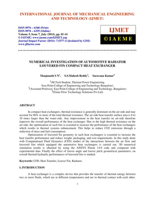
Fig.1: 1. Water filling hole, 2. Cold water to engine, 3. Recycling water to engine,
4. Elliptical tube, 5. Fin, 6. Bottom header plate, 7. Bottom header, 8. Hot water from radiator,
9. Drain cock, 10. Core bracket
Borrajo-Pelaez et al. [1] carried out 3D numerical simulations to compare both an air side and
air/water side model of a plain fin and tube heat exchanger. In their experiment, the influence of the
Reynolds number, fin pitch, tube diameter, fin length and fin thickness were studied. Haci Mehmet
Sahin et al. [2] studied the heat transfer and pressure drop characteristics of seven different fin angles](https://image.slidesharecdn.com/30120140507001-141023065543-conversion-gate01/85/30120140507001-2-320.jpg)
![International Journal of Mechanical Engineering and Technology (IJMET), ISSN 0976 – 6340(Print),
ISSN 0976 – 6359(Online), Volume 5, Issue 7, July (2014), pp. 01-14 © IAEME
with plain fin and tube heat exchangers. This problem was analyzed using Fluent software, and it
was found that a fin with 30º inclination is the optimum one, which gives the maximum heat transfer
enhancement.
3
Mao-Yu Wen et al. [3] have investigated the heat transfer performance of a fin and tube heat
exchanger with three different fin configurations such as plate fin, wavy fin and compounded fin.
This experiment strongly suggested the use of the compound fin configuration for the heat
exchanger. Wei-Mon Yan and Pay-Jen Sheen [4] have carried out an experiment to investigate the
heat transfer and pressure drop characteristics of fin and tube heat exchangers with plate, wavy and
louvered fin surfaces. From this experiment, it is found that at the same Reynolds number, louvered
fin geometry shows larger values of f and j factors, compared with the plate fin surfaces.
Igor Wolf et al. [5] studied the heat transfer performance of a wavy fin and tube heat
exchanger by numerical and experimental methods. They presented some results of a three
dimensional numerical analysis of heat transfer on the air side of a wavy fin and tube heat exchanger.
The three dimensional local flow and thermal fields are well characterized by the numerical analysis.
The developed and presented model demonstrated good heat transfer prediction. It could provide
guidelines for the design optimization of a fin and tube heat exchanger. In this study, three rows of
circular tubes in a staggered arrangement were taken as a domain. The air-side heat transfer and
pressure drop characteristics were successfully modeled using the CFD software Fluent. The
numerical results were validated with the experimental results and the deviation was within 8%.
Tang et al. [6] carried out an experimental and numerical investigation on the air-side
performance of fin and tube heat exchangers with various fin patterns, such as crimped spiral fin,
plain fin, slit fin, fin with delta wing longitudinal vortex generator (VG), and mixed fin with front
6-row vortex generator fin and rear 6-row slit fin. It was found that the heat exchanger with the
crimped spiral fin has better performance than the other four configurations. Also it is found that the
Slit fin offers the best heat transfer performance at a higher Reynolds number. Chi-Chuan Wang et
al. [7] provided flow visualization and pressure drop results for plain fin and tube heat exchangers,
with and without the presence of vortex generators. It was found that the pressure drop of the delta
winglet is lower than that of the annular winglet. Fiebig et al. [8] investigated the local heat transfer
and flow losses in plate fin and tube heat exchangers with vortex generators, to compare the
performance of round and flat tubes. It was found that the heat exchanger with flat tubes and vortex
generators gives nearly twice as much heat transfer with a penalty of 50% pressure loss, when
compared to a heat exchanger with round tubes. Jin-Sheng Leu et al. [9] had performed a numerical
and experimental analysis to study the thermo-hydraulic performance of an inclined block shape
vortex generator embedded plate fin and tube heat exchangers. In this analysis, the effects of
different span angles (30º, 45º and 60º) were investigated for Reynolds numbers ranging from 400 to
3000. It was found that a 30º span angle provides the best heat transfer augmentation and also offers
25% lesser fin surface area.
Jin-Sheng Leu et al. [10] conducted a numerical simulation for louvered fin and tube heat
exchangers having circular and oval tube configurations. The effects of the geometrical parameters
such as louver angle, louver pitches and louver length were discussed. Joen et al. [11] worked on the
interaction between the flow behavior (flow deflection and transition to unsteady flow) and the
thermo-hydraulic performance of an inclined louvered fin design. In this experiment, the impact of
fin pitch, fin angle and Reynolds number were discussed in detail. Zhang and Tafti [12] investigated
the effect of the Reynolds number, fin pitch, louver thickness and louver angle on flow efficiency in
multi-louvered fins and found that the flow efficiency (flow efficiency () = Mean flow angle
(mean) / Louver angle ()) is strongly dependent on geometrical parameters, especially at a low
Reynolds number. The Flow efficiency increases with the Reynolds number and louver angle, while
decreasing with the fin pitch and thickness ratio. Wei Li and Xialing Wang [13] conducted an](https://image.slidesharecdn.com/30120140507001-141023065543-conversion-gate01/85/30120140507001-3-320.jpg)
![International Journal of Mechanical Engineering and Technology (IJMET), ISSN 0976 – 6340(Print),
ISSN 0976 – 6359(Online), Volume 5, Issue 7, July (2014), pp. 01-14 © IAEME
experimental study on the air side heat transfer and pressure drop characteristics of brazed aluminum
heat exchangers, with multi-region louver fins and flat tubes. They found that the heat transfer
coefficients and pressure drop tend to decrease with increasing Reynolds numbers, and increase with
the number of louvers.
4
Wang et al. [14] presented generalized heat transfer and friction correlations for louver fin
geometry having a round tube configuration. They considered different geometrical parameters, such
as louver pitch, louver height, longitudinal tube pitch, transverse tube pitch, tube diameter and fin
pitch for the generation of correlations. Yu-Juei Chang and Chi-Chuan Wang [16] developed a
similar generalized heat transfer correlation for louver fin geometry, using a large data bank. In this
study, different geometrical parameters such as louver angle, tube width, louver length, louver pitch,
fin length and fin pitch were used. For corrugated louver fin geometry, it is shown that 89.3% of the
corrugated louver fin data are correlated within ±15% with a mean deviation of 7.55%. The inclusion
of the plate and tube louver fin data in the heat transfer correlation results in a mean deviation of
8.21%.
It is found from the literature that most of the research works carried out in the field of
compact heat exchangers are presenting j and f factors corresponding to the air side only. However,
the heat transfer performance of the compact heat exchanger under varying conditions of the tube
side fluid is not reported. In the present paper, in addition to the CFD studies carried out for the
louvered fin and elliptical tube compact heat exchanger which is validated with the experimental
results, the heat transferred to the air under different mass flow rate of the water is also reported,
which provides lot of significance.
II. MATHEMATICAL MODELS OF FLUENT
All the fluids investigated in this research are Newtonian. This means that there exists a linear
relationship between the shear stress, sij, and the rate of shear (the velocity gradient). In CFX, this is
expressed as follows:](https://image.slidesharecdn.com/30120140507001-141023065543-conversion-gate01/85/30120140507001-4-320.jpg)
![International Journal of Mechanical Engineering and Technology (IJMET), ISSN 0976 – 6340(Print),
ISSN 0976 – 6359(Online), Volume 5, Issue 7, July (2014), pp. 01-14 © IAEME
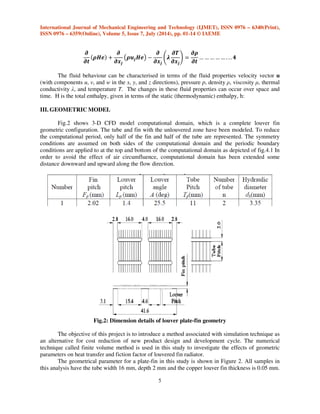
The length of the fins in the airflow direction is 41.6 mm associating with double row tubes.
Simulations are performed for different geometries with various fin pitch (Fp), louver pitch (Lp),
tube pitch (Tp) and louver angle (). The values of these parameters are listed in Table 1. The scope
of this paper is limited to 3 from 15 configurations of T.A. Cowell and A. Achaichia [15].
6
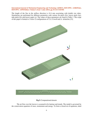
Fig.3: Computational domain
The air flow over the louvers is assumed to be laminar and steady. The model is governed by
the conservation equations of mass, momentum and energy. To form a closed set of equations, ideal](https://image.slidesharecdn.com/30120140507001-141023065543-conversion-gate01/85/30120140507001-7-320.jpg)
![11
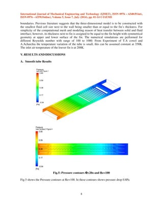
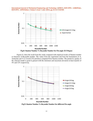
Fig.8: Stanton Number Vs Reynolds Number for Fin angle 25.5 Degree
Figures 8. show the result from this study compared with empirical results of Stanton number
as functions of Reynolds number. The values from the experiment and from the formulation of A.
Achaichia and T.A. Cowell [15] and those computed from Stanton number. The predictive quality of
the selected model is good in general with the minimum and maximum deviation in heat transfer of
4% and 12% respectively
Fig.9: Stanton Number Vs Reynolds Number for different Fin angle](https://image.slidesharecdn.com/30120140507001-141023065543-conversion-gate01/85/30120140507001-13-320.jpg)

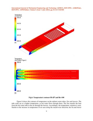
This document discusses a numerical investigation of the geometry of louvered fins in automotive radiator compact heat exchangers. Computational fluid dynamics simulations were performed using ANSYS Fluent to analyze the interactions between air flow and louvered fins. The effects of louver angle and pitch on thermal hydraulic performance were studied. The results were compared to experimental data to validate the simulations. Optimization of louvered fin geometry can increase heat transfer performance while reducing weight and cost requirements.


![5G Explained! A High Level Overview [Introduction]](https://cdn.slidesharecdn.com/ss_thumbnails/5gexplainedahighleveloverview-260119165306-cc137a3e-thumbnail.jpg?width=640&height=640&fit=bounds)


