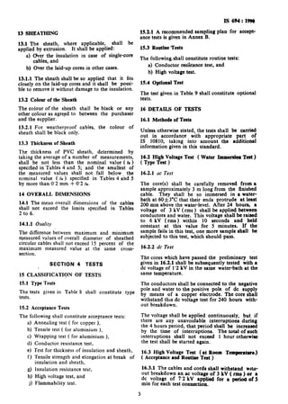
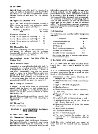
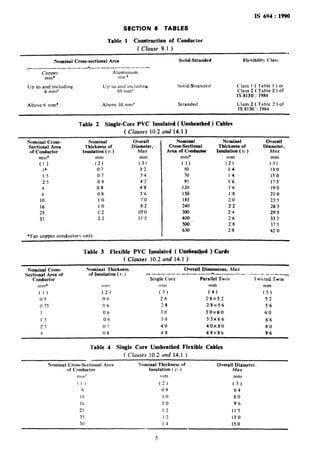
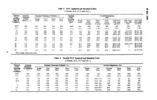
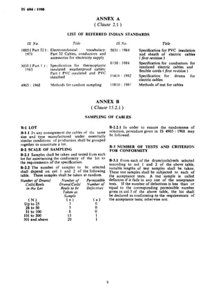
IS 694 : 1990
(Hcallinllcd 1995)
v.TThm
Indian Standard
PVC INSULATED CABLES FOR WORKING
VOLTAGES UP TO AND INCLUDING
1100VOLTS- SPECIFICATION
( Third Revision )
Third Reprint APRIL 1999
UDC 621’315’211 [ 621’315’616’96 1
0 BlS 1991
BUREAU OF INDIAN STANDARDS
MANAK BHAVAN, 9 BAHADUR SHAH ZAFAR MARG
NEW DELHI 110002
February 199 1 Price Croup 4
Power Cables Sectional Committee, ETD 59
FOREWORD
This Indian Standard (Third Revision) was adopted by the Bureau of Indian Standards on
19 February 1990, after the draft finalized by the Power Cables Sectional Committee had been
approved by the Electrotechnical Division Council.
This standard was originally published in 1955 and was subsequently revised in 1964 when it was
split up in two parts, Part 1 dealing with copper conductors and Part 2 dealing with aluminium
conductors. Second revision was brought out in 1977 when the two parts were merged, including
the requirements of weatherproof cables previously covered in IS 3035 (Part 1) : 1965. The two
voltage grades specified as 250/440 V and 650/l 100 V were also merged. The third revision of this
standard has been brought out to take into account the experience gained since then to align with
the international practices, to the extent considered appropriate.
Major changes in this revision include the rationalisation of terms used for the type of cables for
use under special conditions, inclusion of single core flexible cables and five core tlexible cords,
stipulation of overall dimensions and updating the references to the Indian Standards on conductor,
insulation, sheath and methods of tests. Also for single core sheathed cables the process of single
extrusion of insulation and sheath has been eliminated.
While preparing this standard, assistance has been drawn from the following:
IEC Pub 227 : Polyvinyl chloride insulated cables of rated voltages up to and including
450/759 V. International Electrotechnical Commission.
227-l ( 1979) Part 1 : General requirements
227-2 ( 1979) Part 2 : Test methods
227-3 ( 1979) Part 3 : Non-sheathed cables for fixed wiring
227-4 ( 1979) Part 4 : Sheathed cables for fixed wiring
227-5 ( 1979 ) Part 5 : Flexible cables ( cords )
IEC Pub 719 : 1981 Calculation of the lower and upper limits for the average outer dimensions
of cables with circular copper conductors and of rated voltage up to and
including 450/750 V. International Electrotechnical Commission.
BS : 6500 : 1984 Insulated flexible cords and cables. British Standards Institution.
For the purpose of deciding whether a particular requirement of this standard is complied with, the
final value, observed or calculated, expressing the result of a test, shall be rounded off in accordance
with IS 2 : 1960 ‘Rules for rounding off numerical values’. The number of significant places retained
in the rounded off value should be the same as that of the specified value in this standard.
Indian Standard
IS 694 : 1990
PVC INSULATED CABLES FOR WORKING
VOLTAGES UP TO AND INCLUDING
1100VOLTS- SPECIFICATION
( Third Revision )
SECTION 1 GENERAL
1 SCOPE
1.1 This standard covers the requirements and
tests for the following types of unarmoured PVC
insulated cables with copper or aluminium con-
ductors and flexible cords with copper conductors
for electric power and lighting (including weather
proof cables and cables for low temperature
conditions) for voltages up to and including
1100 v.
NOTES
1 For use as weatherproof cables, the cables shall
meet the requirements of additional ageing test
[set 15.4 (c) I.
2 The cables intended for low-temperature conditions
shall meet the requirements of cold bend or cold
impact test whichever is applicable [see 15.4 (a)
and (b) I.
1.1.1
a)
b)
c)
Types IIJ/Cables
Cables for fixed wiring:
i) Single core ( unsheathed);
ii) Single core ( sheathed );
iii) Circular twin, three and four core
( sheathed );
iv) Flat twin with or without ECC
( sheathed ); and
v) Flat three core (sheathed ).
Flexible cables, single core ( unsheathed ).
Flexible cords:
i)
ii)
iii)
iv)
v)
vi)
Single core ( unsheathed );
Single core ( sheathed);
Parallel twin ( unsheathed );
Twisted twin ( unsheathed );
Circular twin, three, four and five core
(sheathed ); and
Flat twin ( sheathed ).
1.2 The cables covered in this standard are
suitable for use on ac single phase or three phase
( earthed or unearthed ) systems for rated voltages
up to and including I 100 V. These cables may
be used on dc systems for rated voltages up to and
including 1 500 V.
1.3 The cables covered in this standard are suit-
able for use where the combination of ambient
temperature and temperature rise due to load
results in a continuous conductor temperature not
exceeding 73’C.
1.4 The cables covered in this standard are also
suitable for use under outdoor or low temperature
conditions provided these meet the additional
requirements as given under type tests. For still
lower temperature, the purchaser may specify the
additional requirements.
2 REFERENCES
2.1 The standards given in Annex A are necessary
adjuncts to this standard.
3 TER[MINOLOGY
3.1 For the purpose of this standard, the defini-
tions given in IS 1885 (Part 32) : 1971 and
IS 10810 ( Part IO) : 1984 shall apply.
3.2 Type Tests
Tests required to be made before supply on a
general commercial basis on a type of cable in
order to demonstrate satisfactory performance
characteristics to meet the intended application.
NOTE - These tests are of such a nature that after
they have been lnade they need not be repeated unless
changes are made in the cable materials or design
which might change the performance characteristics.
3.3 Acceptance Tests
Tests carried out on samples taken from a lot for
the purpose of acceptance,of the lot.
3.4 Routine Tests
Tests made by manufacturer on all finished cable
lengths to demonstrate the integrity of the cable.
3.5 Optional Tests
Special tests to be carried out when required by
agreement between the purchaser and the supplier.
SECTION 2 MATERIALS
4 CONDUCTOR
4.1 Copper Conductor
The conductor sh,tll he composed of pl:lin
annealed high conducti ity copper wires cc)m-
plying with IS 8 130 : 1983.
4.2 Aluminium Couducror
The conductor shall be com;losed of aluminium
wires complying with IS 8130 : 1984.
4.3 A separator tape made of suitable material
may be applied over conductor at the discretion
of the manufacturer.
1
IS 694 : 1990
5 INSULATION
5.1 The insulation shall be of PVC compound’
conforming to the requirements of Type A of
IS 5831 : 1984.
6 FILLERS
6.1 The fillers shall consist of vulcanized rubber,
unvulcanized rubber, thermoplastic compound or
textile materials.
6.2 The filler materials shall be suitable for
operating temperature of the cable and compatible
with othy components of the cable. These shall
not be harder than PVC used for insulation and
sheath.
7 BINDER TAPE
7.1 Binder tape shall consist of plastic or proofed
textile material.
8 SHEATH
8.1 The sheath shall consist of PVC compound
conforming to the requirements of ST 1 type of
IS 5831 : 1984.
SECTION 3 CONSTRUCTION
9 CONDUCTOR
9.0 Nominal cross sectional area of conductor of
cables covered in this standard is given iu
respective tables.
9.1 Cables for Fixed Wiring
The construction of conductors for fixed wiring
shall be as given in Table 1.
9.1.1 Conductors of nominal area less than 16
mm’ shall be circular only. Conductors of
nominal area 16 mm2 and above may be circular
or shaped.
9.2 Flexible Cables and Cords
The conductor shall be according to flexibility
Class 5 of IS 8130 : 1984.
9.3 A separator tape may be applied over the
conductor ( see 4.3 ).
10 1NSULATION
10.1 The conductor shall be provided with PVC
insulation applied by extrusion.
10.2 Thickness of Insulation
The average thickness of insulation shall be not
less than the nominal value ( fi ) specified in
Tables 2.to 6.
10.3 Tolerance on Thickness of Insulation
The smallest of the measured values of thickness
of insulation shall not fall below the nominal
value ( fi ) specified in the relevant tables by more
than ( 0’1 mm + 0’1 ti ).
10.4 Application of InsuIation
The insulation shall be so applied that it fits I
closely on the conductor and it shall be. possible
to remove it without damage to the conductor.
11 CORE IDENTIFICATION
11.1 Cores shall be indentified by different
colouring of PVC insulation. The colour, scheme
as given in Table 7 shall be adopted.
12 LAYING-UP OF CORES
12.1 Flat Twin and Three-Core Cables ( Without
ECC )
Two or three cores shall be laid side by side.
12.2 Flat Twin Cables ( with ECC )
Two cores with a bare ECC shall be laid side by
side in the same plane (ECC occupying the
central position ).
12.3 Circular Twin, Three- and Four-Core Cables
Two, three or tour cores shall be laid together
with a suitable right-handc lay. The interstices
between the cores may be filled with fillers. A
binder tape may be applied over the laid-up cores.
12.4 Circular Twin, Three, Four and Five Core
Flexible Cords
Two, three, four or five cores shall be twisted
together with a suitable right-hand lay. The
interstices may be filled with sheathing material,
fillers or strengthening cords of textile or any
other suitable material.
12.5 Parrllel Twin ( Unsheathed ) Flexible Cords
TWOconductors shall be laid parallel and insulat-
ed simultaneously such that the cores can be
separated readily without damage,
12.6 Twisted Twin ( Unsheathed ) Flexible Cords
Two cores shall be twisted together with a suitable
right hand lay:
12.7 Flat Twin ( Sheathed ) Flexible &r&
Two cores shall be laid side by side.
2
IS 694: l!WO
152.1 A recommended sampling plan for accept-
ance tests is given in Annex B.
15.3 Routine Tests
The following&all constittite routine tests:
a) Conductor resi’stance test, and
b) High voltage test.
15.4 Optional Test
The test’ given in Table 9 shall constitute optional
tests.
13 SHEATHING
13.1 The sheath, where applicable, shall be
applied by extrusion. It shall be applied:
a) Over the insulation in case of single-core
cables? and
b) Over the laid-up cores in other cases.
13.1.1 The sheathshall be so applied that it fits
closely on the laid-up cores and it shall be possi-
ble to remove it without damage to the insulation.
13.2 Colour of the Sheath
The colour of the sheath shall be black or any
other colour as agreed to between the purchaser
and the supplier.
13.2.1 For weatherproof cables, the colour of
sheath shall be black only.
13.j Thickness of Sheath
The thickness of PVC sheath, determined by
taking the average of a number of measurements,
shall be not less than the nominal value ( k )
specified in Tables 4 and 5; and the smallest of
the measured values shall not fall below the
nominal value ( fa ) specified in Tables 4 ahd 5
by more than 0’2 mm + 0’2 tn.
14 OVERALL DIMENSIONS
14.1 The mean overall dimensions of the cables
shall not exceed the limits specified in Tables
2 to 6.
14.1.1 Ova&y
The difference detween maximum and minimum
measured values of overall diameter of sheathed
circular cables shall not exceed 15 percent of the
maximum measured value at the same cross-
section.
SECTION 4 TESTS
15 CLASSIFICATION OF TESTS
15.1 Type Tests
The tests given in Table 8 shall constitute type
tests.
15.2 Acceptance Tests
The following shall constitute acceptance tests:
a)
b)
4
4
4
f)
d
h)
3
Annealing test ( for copper ),
Tensile test ( for aluminium ),
Wrapping test ( for aluminium ),
Conductor resistance test,
rest for thickness of insulation and sheath,
Tensile strength and elongation at break of
insulation and sheath,
Insulation resistance test,
High voltage test, and
Flammability test.
16 DETAILS OF TESTS
16.1 Methods of Tests
Unless otherwise stated, the tests shall be carried
out in accordance with appropriate part of
IS 10810, taking into account the additional
information given in this standard.
16.2 High Voltage Test ( Water Immeraiqn Test )
( Type Test )
16.2.1 ac Test
The core(s) shall be carefully removed from a
sample approximately 3 m long from the finished
cable. They shall be so immersed in a water-
bath at 60f3”C that their ends protrude at least
200 mm above the water-ievel. After 24 hours, a
voltage of 3 kV (rms ) shall be applied between
conductors and water. This voltage shall be raiti
to 6 kV (rms) within 10 seconds and held
constant at this value for 5 minutes. If the
sample fails in this test, one more sample ehall be
subjected to this test, which should pass.
16.2.2 dc Test
The cores which have passed the preliminary test
given in 16.2.1 shall be subsequently tested with a
dc voltage of 1’2 kV in the same water-bath at the
same temperature.
The conductors shall be connected to the negative
pole and water to the positive pole of dc supply
by means of a copper electrode. The core shall
withstand thrs dc voltage test for 240 hours with-
out bieakdown.
The voltage shall be applied continuously, but if
there are any unavoidable interruptions during
the 4 hours period, that period shall be increased
by the time of interruptions. The total of such
interruptions shall not exceed 1 hour otherwise
the test shall be started again.
16.3 High Voltage Test (at Room Temperrtaw)
( Acceptance and Routine Test )
16.3.1 The cables and cords shall withstand wrtn-
out breakdown an ac voltage of 3 kV ( rms ) oi a
dc voltage of 7’2 kV applied for a m of 5
min for each test connection.
3
IS 694:1990
16.3.1.1 Single-core cables shall be immersed in
water at ambient temperature one hour before
the testing and the test voltage shall be applied
between conductor and water for the specified
period.
16.4 Spark Test ( Routine Test )
Spark test may be carried out as an alternate to
high voltage on single core unsheathed cables.
The voltage shall be as specified below:
Thickness o_f Insulation Test Voltage
mm kV (rms)
Up to and including 1’0 6
Above 1’0 and up to and including 1’5 10
Above 1’5 and up to and including 2’0 15
Above 2’0 and up to and including 2’5 20
Above 2’5 25
16.5 Flammability Test
The period of burning after removal of Hame shall
not exceed 60 seconds and the unaffected
( uncharred ) portion from the lower edge of the
top clamp shall be at least 50 mm.
16.6 Additional Ageing Test ( For Cablea for
Outdoor Use )
16.6.1 Ageing qf Sample
A sample, 6 m long, of the finished cable shall be
suspended in a heating chamber and exposed to
a temperature of 80 +2”C during a period of
168 hours. Immediately after this, the sample
shall be placed in a bath of boiling water for a
period of 8 hours and in a water-bath at 25°C
for 16 hours. This procedure shall be repeated on
5 successive days. The ends of the sample shall
protrude at least 200 mm above the water level.
16.6.2 Testing and Evaluation
A sample, 5 m long, taken from the conditioned
sample shall be tested for high voltage test in
accordanc’e with 16.3. The test has however, to be
carried out on the finished cable and in a water
bath at 60&3”C.
16.6.2.1 The remaining conditioned sample shall
be submitted to cold bend cold impact test as
appropriate.
16.7 Flexing Test
Under consideration.
SECTION 5 IDENTIFICATION, PACKING
AND MARKING
17 IDENTIFICATION
17.1 Manufacturer’s Identification
The manufacturer shall be identified throughout
the length of the cable by means of a tape bearing
the manufacturer’s name or trade-mark, or by
manufacturer’s name or tradesmark being printed,
indented or embossed on the cable. In case none
of these methods can be employed, or if the
purchaser so desires, colour identi&ation thread(s)
in accordance with a scheme to be approved by
the Bureau of Indian Standards shall be employad.
The printing, indentation or embossing shall be
done on the insulation in case of unsheathed
cables and on the sheath in case of sheathed
cables. The distance between any two consecutive
printings, indentations or embossings shall be not
more than 1 m.
17.2 Cable Code
The following code
the cable:
Colistituent
shall be used for designating
Code Lutter
Aluminium conductor A
PVC insulation Y
PVC sheath Y
Earth continuity conductor (ECC)
Suitable for outdoor use ou
Suitable for low temperature sz
NOTE - No code letter is required when the con-
ductor material is copper.
18 PACKING PND MARKING
18.1 The cable shall be either wound on drums
( see. IS 10418 : 1982 ) reels or supplies in coils
packed.
18.2 The cable shall carry the following informa-
tlon either stencilled on the reel or drum or con-
ained in a label attached to it:
I, fora) Reference to this Indian Standard
example, Ref IS 694;
b) Manufacturer’s name, brand name or
mark;
trade-
c) Type of cable and voltage grade;
d) Number of cores;
e) Nominal cross-sectional area of conductor;
f )
g)
h)
9
k)
ml
11)
P)
4)
18.2.1
Cable code;
Colour of core (in case of single core
cables );
Length of cable on the reel, drum or coil;
Number of lengths on the reel, druin or
coil (if more than one );
Direction of rotation of drum (by means
of arrow );
Approximate gross mass;
Country of manufacture;
Year of manufacture; and
The word ‘suitable for outdoor use’ or
‘suitable for low temperature’, wherever
applicable.
The cable (packed coil, reel, drum or. .
label ) may also be marked with the Standard
Mark.
IS 694 : 1990
SECTION 6 TABLES
Table 1 Construction of Conductor
( czuuse 9.1 )
Nominal Cross-sectional Area
c_________--h-_---_--_----.
Copper Aluminium
mm* mn 1
Up to and including Up lo and including
6 mm2 10 mm?
Solid/Stranded
Solid/Stranded
Flexibilit? <‘Ias
Class I ( Table 1 ) or
Class 2 ( Table 2 ) of
1s 8130 : 1984
Above 6 mm’ Above 10 mm’ Stranded Class 2 ( Table 2 1 of
IS 8130 : 1984
Table 2 Single-Core PVC Insulited ( Unsheathed ) Cables
( Chuses 10.2 and 14.1 )
Nominal Cross- Nominal
Sectional Area Thickness of
of Conductor Insulation ( 11)
Overall Nominal
Diameter,
I
Cross-Sectional
Max Area of Conductor
mm’ mm
(1) (2)
10 0’7
1’5 0‘7
2’5 0’8
4 0’8
6 0’8
10 I’0
16 1’0
25 1’2
35 12
*For copper conductors only.
3’2
3’4
4’2
4’8
5’6
7’0
8’2
10’0
1I’S
mm*
(1)
50
70
95
120
150
185
240
300
400
500
630
Ncminal
Thickness of
Insulation (ti )
;1?:
I’4
1’4
I’6
1’6
I’8
2’0
2’.2
2’4
2’6
2’8
2’8
Overall
Diameter,
Mnx
mm
(3)
13’0
15’0
17.5
19’0
21’0
23’5
26’5
29’5
33.5
37’5
42’0
Table 3 Flexible PVC Insulated ( Unsheathed ) Cords
( CIuuscs 10.2 and 14.1 )
Nominal Cross-
Sectional Area of
Conductor
Nominal Thickness
of Insulation ( tI J
Overall Dimensions, Max
c------------ *------_.‘---_____--,
Single Core Parallel Twin Twisted Twin
mm’ nim mm
( 1 ) (2) (3)
0’ 5 0.6 2‘6
0’75 0’6 2’8
I 0’6 3’0
I’5 0.6 3’8
2’5 0’7 4’0
4 0’ 8 4’8
mm
(5)
2’6~ 5’: 5’2
2’8x5’6 5’6
3’0~ 6’0 6’0
3’3x6’6 6’6
4’0 x 8’0 8’0
4’8x9’6 9’6
Table 4 Single Core Unsheathed FIexible Cables
( CIozrses 10.2 nnd 14.1 )
Nominal Cross-Sectional Area Seminal Thickness of
of Conductor Insulation ( f I )
Overall~~;meter.
mm= mm mm
( 1 ) (2) (3)
6 0’8 6’4
IO I’0 8.0
16 I’0 9’6
25 I’2 11’5
35 I’2 13’0
50 I’4 150
Table 5 PVC Insulated and sheathed Cables 5
( Claws 10.2, 13.3, and 14.1 )
2
Nominal Nominal Nominal Thickness of Sheath ( fS ) Nominal Overali IXrnensions.
.“
w
Cross- Thidmess ~ .—...----. = Cross-
st!ct!colaJl Single ~
MrJx
of Inm- ‘rwi n Three Four .Sectionai
Iation ( r, )
,———- ————— _____ A—.— ————— ——
Core Core Core
—.—
Core Area of Single Twin
Conductor
Flat Twin Flat Twin Flat Twin
ECC Core Core c:: ;&- Core with Core with-
Circular Ecc out ECC
mm’ nml mm mm mm mma mm
(1) (Y (3) (,4) (5) (6} (7) :8; (9)
0% ()’8; ‘. 09 09 0’9
0“6
1“o
08
4’7
0.9
8’2
2’5
0“9 09
0’-1 0’8
5’0
1“0 1“o 1“o
;:;
5“8
~:.;
4 08 tY9 1“o 1“1
0“8
1“5
09
6“8 12“0
1$
1“1 1“1 l;
1’()
25
0’9
7“8
1“2 1’2
13”5
1“3 4“0 8’8 J6’5
1“()
E 1“o 1“3 1’3 1“4
1“2
60 10”5
1“1
19”0
35
1“4 1“s 1“6 —
1‘2 1“1
12”5 23”0
1“5 I “6 1“7 13’5 25”5
50 1“4 1“2 1“6 1’7 1-8 15”5 29”5
:$r;<
Circular
(%)
8’6
9“2
11”0
13”0
14”5
17”5
200
24”5
27”5
31”5
Four
Core
Circular
(v’)
1;”;
12’0
14’0
15”5
19”5
225
27”5
305
35”0
(%’)
7-8x 5“0
8“4X 5“4
100 X 6“4
11”5x 72
13”OX 8’0
16”OX 9’6
185 X11”0
22”5 x 13”0
25”5 X 14”5
290x16’5
(Y’)
9“2 X 5’0
102 x 5“4
12”OX64
13-5x7’2
15”5x8’O
19”OX9”6
220X 11”0
—
—
mm
(14)
10”5 x 3“0
11”5X 54
14”OX 6’4
16”5x 7’4
.;:03 ;“:
265x11’O
32”5x18”5
36’0x15”0
41”5X17”0
u?
qFor copper conductors only.
Table 6 Flexible PVC Imulated and Sheathed Cords
( Clauses 10.2, 13.3 and 14.1 )
Nominal Nominal Nominal Thickness of Sheath ( (S )
Cross- Thickness
Overall Dimensions, Max
r —- —.~—_._y
sectional
.——. — . ..— ~. ..—.—————.
of Insulation Single Two Three Four Five po:: Flat
Area of
C:Mar Three Four Five
(1( ) Core Core Core Core Core Twin Core Core Ore
Conductor
mma mm mm
(1) (Y (3) 74m) (5) (;T (;; (:; (;; ( :07 H’) (’v) (Y)
05 0“6 0“9 0“9 09 0’9 0’9 4’5 4“9x 7“2 7“2 7’6 fr2 90
0’75 0’6 09 09 09 09 09 47 5“2x 7-8 7“8 8“2 88 96
; 0’6 09 09 09 09 1“o 4“9 5“4x 8“0 8“0 8“6 9’4 105
~.
.5 0“6 09 09 09 1“0 1“o 5“4 5“6x 86 8“6 9’2 105 11’0
2’5 07 1“o 1“o 1“0 1“o i.0 62 6’6X 10⁵ 105 11”0 120 13”0
4 0“8 !“0 1.0 1“0 1“0 1’1 7“0 7-4x 120 120 125 140 1Y5
.
IS 694 : 1990
Table 7 Core Identification
(Chuse 11.1 )
Cables for Fined Wiring Flexible Cords Flexible Cables
I Core Red, Black, Yellow, Blue. Red, Black. Yellow, Blue, Red, Black, Yellow, Blue,
White or Grey White or Grey White or Grey
2 Core Red and Black Red and Black -
3 Cores Red, Yellow and Blue Red, Blach and Yellow-green -
( for ECC )
4 Cores Red. Yellow, Blue and Black Red, Yellow. Blue and Yellow- -
green ( for ECC )
5 Cpres Red. Yellow. Blue, Black and -
Grey
tiOTES
1 In case of single-core cables used for control wiring of switchgear any colour other than the above shall be
permissible as agreed to between the purchaser and the supplier.
2 The colour of insulation for parallel twin flexible cords may be Red, Black. Yellow, Blue, White or Grey.
The cores may be identified by a longitudinal rib on one core.
3 For tb time being, green colour for ECC is also permissible.
Table 8 Type Tests
(Chuse 15.1 )
Test
a) Tests on conductor
i) Annealing test ( for copper)
ii) Tensile test (for aluminium)
iii) Wrapping test (for aluminium )
iv) Resistance test
b) Test for overall dimensions and thickness of
insulation and sheath
c) Physical tests for insulation and sheath
i) Tensile strength and elongation at break
ii) Loss of mass test
iii) Ageing in air oven
iv) Shrinkage tesl
v) Heal shock test
vi) Hot deformation
d) Insulation resistance
e) High voltage test ( water immersion test )
f) Flammability test
For Requirements, Ref
IS 8130 : 1984
IS 8130 : 1984
IS 8i30 : 1984
IS 8130 : 1984
10, 13, I4
Tables 1 to 5 of IS 694
IS 5831 : 1984
IS 5831 : 1984
IS 5831 : 1984
IS 5831 : 1984
IS 5831 : 1984
IS 5831 : 1984
IS 5831 : 1984
16.2 of IS 694
16.5 of IS 694
For Test Method,
Ref Part No. of
IS loJO
1
2’
3
5
6
7
IO
II
I2
14
I5
43
45
53
..
Table 9 Optional Tests
( Clause 15.4 )
Test For Requirements, Ref
;I) Cold bend test IS 5831 : 1984
h) Cold impact test IS 5831 : 1984
c) Additional ageing test 16.6 of IS 6Y4
d) Flexing test 16.7 of IS 694
For Test Method,
Ref Part No. IS 10810
20
21
-
-
NOTE - It shall be permissible to carry out the routine tests on manufacturing lengths in piace of individual
shipping lengths.
7
IS 694 : 1990
IS No.
1885 ( Part 32 1:
1971
3035 ( Part 1 ) :
1965
4905 : 1968
ANNEX A
( Clause 2.1 )
LIST OF REFERRED INDIAN STANDARDS
Title IS No. Title
Electrotechnical vocabulary: 5831 : 1984
Part 32 Cables, conductors and
Specification for PVC insulation
and sheath of electric cables
accessories for electricity supply ( first revision )
Specification for thermoplastic
8130 : I984 Specification for conductors for
insulated weatherproof cables:
insulated electric cables and
Part 1 PVC insulated and PVC
flexible cords (first revision )
sheathed 10418 : 1982 Specification for drums for
electric cables
Methods for random sampling 10810: 19%’ Methods of test for cables
ANNEX B
( Clause 15.2.1 )
SAMPLING OF CABI,ES
B-l LOT
B-J.1 17 any consignment the cables of the same
size and type manufactured under essentially
similar conditions of production shall be grouped
together to constitute a lot.
B-2 SCALE OF SAMPLING
B-2.1 Samples shall be taken and tested from each
lot for ascertaining the conformity of the lot to
the requirements of the specification.
B-2.2 The number of samples to be selected
shall depend on co1 I and 2 of the following
table. These samples shall be taken at random.
Number of Drums/ Number of Permissible
Coils/ Reels Drums/Coils/ Number of
in the Lot Reels to be Defectives
Taken as
Sumple
(N).
Up to 25 (;I
C;)
26 to 50
51 to loo 8’ 0”
101 to 300 1
301 and above 1
B-2.2.1 In order to ensure the randomness of
selection, procedure given in IS 4905 : 1968 may
be followed.
B-3 NUMBER OF TESTS AND CRITERIOfi
FOR CONFORMITY
B-3.1 From each of the drum/coils/reels selected
according to co1 1 and 2 of the above table,
suitable lengths of test samples shall be taken.
These test samples shall be subjected to each of
the acceptance tests. A test sample is called
defective if it fails in any one of the acceptance
tests. If the number of defectives is less than or
equal to the corresponding permissible number
given in co1 3 of the above table, the lot shall
be declared as conforming to the requirements of
the acceptance tests; otherwise not.
s
Bureau of Indian Standards
BIS is a statutory institution established under the Bureau of Indian Standards Act, 1986 to promote
harmonious development of the activities of standardization, marking and quality certification of goods and
attending to connected matters in the country.
Copyright
BE has the copyright of all its publications. No part of these publications may be reproduced in any form
without the prior permission in writing of BIS. This does not preclude the free use, in the course of
implementing the standard, of necessary details, such as symbols and sizes, type or grade designations.
Enquiries relating to copyright be addressed to the Director (Publication), BIS.
Review of Indian Standards
Amendments are issued to standards as the need arises on the basis of comments. Standards are also reviewed
periodically; a standard along with amendments is reaffirmed when such review indicates that no changes are
needed; if the review indicates that changes are needed, it is taken up for revision. Users of Indian Standards
should ascertain that they are in possession of the latest amendments or edition by referring to the latest issue
of ‘BIS Handbook’ and ‘Standards Monthly Additions’.
This Indian Standard has been developed from Dot: No. ETD 59 (2988)
Amendments Issued Since Publication
Amend No. Date of Issue Text Affected
BUREAU OF INDIAN STANDARDS
Headquarters:
Manak Bhavan, 9 Bahadur Shah Afar Marg, New Delhi 110002
Telephones: 323 0131,323 33 75,323 94 02
Telegrams: Manaksanstha
(Common to all offices)
Regional Offices: Telephone
Central : Manak Bhavan, 9 Bahadur Shah Zafar Marg
NEW DELHI 110002
Eastern :
Northern :
l/14 C.I.T. Scheme VII M, V.I.P. Road,,Maniktola
CALCUTI’A 700054
SC0 335336, Sector 34-A, CHANDIGARH 160022
Southern : C.I.T. Campus, IV Cross Road, CHENNAI 600113
Western :
Branches :
Manakalaya, E9 MIDC, Marol, Andheri (East)
MUMBAI 400093
AHMADABAD. BANGALORE. BHOPAL. BHUBANESHWAR.
COIMBATORE. FARIDABAD. GHAZIABAD. GUWAHATI.
HYDERABAD. JAIPUR. KANPUR. LUCKNOW. NAGPUR.
PATNA. PUNE. THIRUVANANTHAPURAM.
323 76 17,323 38 41
337 84 99,337 85 61
337 86 26,337 9120
{
60 38 43
60 20 25
{
235 02 16,235 04 42
235 15 19,235 23 15
{
832 92 95,832 78 58
832 78 91,832 78 92
Printed at Dee Kay Printers, New Delhi, India
AMENDMENT NO. 1 APRIL 1998
TO
IS 694 : 1990 PVC INSULATED CABLES FOR
WORKING VOLTAGES UP TO AND INCLUDING
1 100 VOLTS - SPECIFICATION
( Third Revision )
(Page 1, &ruse 1.1, line 5 ) - Substitute ‘(including cables for outdoor use
and ....)’ f or ‘ inc u in( 1 d g weather proof cables and ....)‘.
(Page 1, clause 1.1, Note 1 ) -Substitute the following for the existing:
‘1 For cables for outdoor use, the cables shall meet tbe requirements of additional ageing test
( se= 15.4 )‘.
( Page 1, clause 1.1, Note 2, kzsr line) - Substitute ‘(XC15.4) for ‘[see
15.4 (a) and (b) 1’.
( Page 6, Table 5, co1 14 ) - Substitute ‘Flat Three Core without ECC’ for
‘Flat Twin Core without ECC’.
(Page 6, Table 5, co1 14, Row 1 ) - Substitute ‘10.5 x 5.0’ for ‘10.5 x 3.0’.
(Page 6, Table 5, co1 14, Row 4 ) -Substitute ‘16.5 x 7.2’for ‘16.5 x 1.4’.
(Page 6, Table 5, co1 14, Row 8 ) - Substitute ‘32.5 x 13.5’ for ‘32.5 x 18.5’.
( Page 6, Table 6, co! 11 ) - Insert the following new column as column
(12) and renumber the existing columns (12) and (13) as (13) and (14)
respectively:
Flat%u.
Core,mm
(12)
4.9 X 9.6
5.2 x 10.5
5.4 x 11.0
5.6 x 12.0
6.6 x 14.0
7.4 x 16.5
Prmted at Dee Kay Printers, New Delhi-l 10015, India.
AMENDMENT NO. 2 JANUARY 2001
TO
IS 694-:1990 PVC INSULATED CABLES FOR
WORKING VOLTAGES UP TO AND INCLUDING 1100 V
— SPECIFICATION
( Third Revision)
( Page 4, clause 16.6.1, first line) — Substitute ‘A sample of at Ieaat 6 m
long’ for ‘A sample, 6 m long’.
(ETD09)
Reprography Unit, BIS, New Delhi, India

3 is 694 pvc cables

  • 1.
    IS 694 :1990 (Hcallinllcd 1995) v.TThm Indian Standard PVC INSULATED CABLES FOR WORKING VOLTAGES UP TO AND INCLUDING 1100VOLTS- SPECIFICATION ( Third Revision ) Third Reprint APRIL 1999 UDC 621’315’211 [ 621’315’616’96 1 0 BlS 1991 BUREAU OF INDIAN STANDARDS MANAK BHAVAN, 9 BAHADUR SHAH ZAFAR MARG NEW DELHI 110002 February 199 1 Price Croup 4
  • 2.
    Power Cables SectionalCommittee, ETD 59 FOREWORD This Indian Standard (Third Revision) was adopted by the Bureau of Indian Standards on 19 February 1990, after the draft finalized by the Power Cables Sectional Committee had been approved by the Electrotechnical Division Council. This standard was originally published in 1955 and was subsequently revised in 1964 when it was split up in two parts, Part 1 dealing with copper conductors and Part 2 dealing with aluminium conductors. Second revision was brought out in 1977 when the two parts were merged, including the requirements of weatherproof cables previously covered in IS 3035 (Part 1) : 1965. The two voltage grades specified as 250/440 V and 650/l 100 V were also merged. The third revision of this standard has been brought out to take into account the experience gained since then to align with the international practices, to the extent considered appropriate. Major changes in this revision include the rationalisation of terms used for the type of cables for use under special conditions, inclusion of single core flexible cables and five core tlexible cords, stipulation of overall dimensions and updating the references to the Indian Standards on conductor, insulation, sheath and methods of tests. Also for single core sheathed cables the process of single extrusion of insulation and sheath has been eliminated. While preparing this standard, assistance has been drawn from the following: IEC Pub 227 : Polyvinyl chloride insulated cables of rated voltages up to and including 450/759 V. International Electrotechnical Commission. 227-l ( 1979) Part 1 : General requirements 227-2 ( 1979) Part 2 : Test methods 227-3 ( 1979) Part 3 : Non-sheathed cables for fixed wiring 227-4 ( 1979) Part 4 : Sheathed cables for fixed wiring 227-5 ( 1979 ) Part 5 : Flexible cables ( cords ) IEC Pub 719 : 1981 Calculation of the lower and upper limits for the average outer dimensions of cables with circular copper conductors and of rated voltage up to and including 450/750 V. International Electrotechnical Commission. BS : 6500 : 1984 Insulated flexible cords and cables. British Standards Institution. For the purpose of deciding whether a particular requirement of this standard is complied with, the final value, observed or calculated, expressing the result of a test, shall be rounded off in accordance with IS 2 : 1960 ‘Rules for rounding off numerical values’. The number of significant places retained in the rounded off value should be the same as that of the specified value in this standard.
  • 3.
    Indian Standard IS 694: 1990 PVC INSULATED CABLES FOR WORKING VOLTAGES UP TO AND INCLUDING 1100VOLTS- SPECIFICATION ( Third Revision ) SECTION 1 GENERAL 1 SCOPE 1.1 This standard covers the requirements and tests for the following types of unarmoured PVC insulated cables with copper or aluminium con- ductors and flexible cords with copper conductors for electric power and lighting (including weather proof cables and cables for low temperature conditions) for voltages up to and including 1100 v. NOTES 1 For use as weatherproof cables, the cables shall meet the requirements of additional ageing test [set 15.4 (c) I. 2 The cables intended for low-temperature conditions shall meet the requirements of cold bend or cold impact test whichever is applicable [see 15.4 (a) and (b) I. 1.1.1 a) b) c) Types IIJ/Cables Cables for fixed wiring: i) Single core ( unsheathed); ii) Single core ( sheathed ); iii) Circular twin, three and four core ( sheathed ); iv) Flat twin with or without ECC ( sheathed ); and v) Flat three core (sheathed ). Flexible cables, single core ( unsheathed ). Flexible cords: i) ii) iii) iv) v) vi) Single core ( unsheathed ); Single core ( sheathed); Parallel twin ( unsheathed ); Twisted twin ( unsheathed ); Circular twin, three, four and five core (sheathed ); and Flat twin ( sheathed ). 1.2 The cables covered in this standard are suitable for use on ac single phase or three phase ( earthed or unearthed ) systems for rated voltages up to and including I 100 V. These cables may be used on dc systems for rated voltages up to and including 1 500 V. 1.3 The cables covered in this standard are suit- able for use where the combination of ambient temperature and temperature rise due to load results in a continuous conductor temperature not exceeding 73’C. 1.4 The cables covered in this standard are also suitable for use under outdoor or low temperature conditions provided these meet the additional requirements as given under type tests. For still lower temperature, the purchaser may specify the additional requirements. 2 REFERENCES 2.1 The standards given in Annex A are necessary adjuncts to this standard. 3 TER[MINOLOGY 3.1 For the purpose of this standard, the defini- tions given in IS 1885 (Part 32) : 1971 and IS 10810 ( Part IO) : 1984 shall apply. 3.2 Type Tests Tests required to be made before supply on a general commercial basis on a type of cable in order to demonstrate satisfactory performance characteristics to meet the intended application. NOTE - These tests are of such a nature that after they have been lnade they need not be repeated unless changes are made in the cable materials or design which might change the performance characteristics. 3.3 Acceptance Tests Tests carried out on samples taken from a lot for the purpose of acceptance,of the lot. 3.4 Routine Tests Tests made by manufacturer on all finished cable lengths to demonstrate the integrity of the cable. 3.5 Optional Tests Special tests to be carried out when required by agreement between the purchaser and the supplier. SECTION 2 MATERIALS 4 CONDUCTOR 4.1 Copper Conductor The conductor sh,tll he composed of pl:lin annealed high conducti ity copper wires cc)m- plying with IS 8 130 : 1983. 4.2 Aluminium Couducror The conductor shall be com;losed of aluminium wires complying with IS 8130 : 1984. 4.3 A separator tape made of suitable material may be applied over conductor at the discretion of the manufacturer. 1
  • 4.
    IS 694 :1990 5 INSULATION 5.1 The insulation shall be of PVC compound’ conforming to the requirements of Type A of IS 5831 : 1984. 6 FILLERS 6.1 The fillers shall consist of vulcanized rubber, unvulcanized rubber, thermoplastic compound or textile materials. 6.2 The filler materials shall be suitable for operating temperature of the cable and compatible with othy components of the cable. These shall not be harder than PVC used for insulation and sheath. 7 BINDER TAPE 7.1 Binder tape shall consist of plastic or proofed textile material. 8 SHEATH 8.1 The sheath shall consist of PVC compound conforming to the requirements of ST 1 type of IS 5831 : 1984. SECTION 3 CONSTRUCTION 9 CONDUCTOR 9.0 Nominal cross sectional area of conductor of cables covered in this standard is given iu respective tables. 9.1 Cables for Fixed Wiring The construction of conductors for fixed wiring shall be as given in Table 1. 9.1.1 Conductors of nominal area less than 16 mm’ shall be circular only. Conductors of nominal area 16 mm2 and above may be circular or shaped. 9.2 Flexible Cables and Cords The conductor shall be according to flexibility Class 5 of IS 8130 : 1984. 9.3 A separator tape may be applied over the conductor ( see 4.3 ). 10 1NSULATION 10.1 The conductor shall be provided with PVC insulation applied by extrusion. 10.2 Thickness of Insulation The average thickness of insulation shall be not less than the nominal value ( fi ) specified in Tables 2.to 6. 10.3 Tolerance on Thickness of Insulation The smallest of the measured values of thickness of insulation shall not fall below the nominal value ( fi ) specified in the relevant tables by more than ( 0’1 mm + 0’1 ti ). 10.4 Application of InsuIation The insulation shall be so applied that it fits I closely on the conductor and it shall be. possible to remove it without damage to the conductor. 11 CORE IDENTIFICATION 11.1 Cores shall be indentified by different colouring of PVC insulation. The colour, scheme as given in Table 7 shall be adopted. 12 LAYING-UP OF CORES 12.1 Flat Twin and Three-Core Cables ( Without ECC ) Two or three cores shall be laid side by side. 12.2 Flat Twin Cables ( with ECC ) Two cores with a bare ECC shall be laid side by side in the same plane (ECC occupying the central position ). 12.3 Circular Twin, Three- and Four-Core Cables Two, three or tour cores shall be laid together with a suitable right-handc lay. The interstices between the cores may be filled with fillers. A binder tape may be applied over the laid-up cores. 12.4 Circular Twin, Three, Four and Five Core Flexible Cords Two, three, four or five cores shall be twisted together with a suitable right-hand lay. The interstices may be filled with sheathing material, fillers or strengthening cords of textile or any other suitable material. 12.5 Parrllel Twin ( Unsheathed ) Flexible Cords TWOconductors shall be laid parallel and insulat- ed simultaneously such that the cores can be separated readily without damage, 12.6 Twisted Twin ( Unsheathed ) Flexible Cords Two cores shall be twisted together with a suitable right hand lay: 12.7 Flat Twin ( Sheathed ) Flexible &r& Two cores shall be laid side by side. 2
  • 5.
    IS 694: l!WO 152.1A recommended sampling plan for accept- ance tests is given in Annex B. 15.3 Routine Tests The following&all constittite routine tests: a) Conductor resi’stance test, and b) High voltage test. 15.4 Optional Test The test’ given in Table 9 shall constitute optional tests. 13 SHEATHING 13.1 The sheath, where applicable, shall be applied by extrusion. It shall be applied: a) Over the insulation in case of single-core cables? and b) Over the laid-up cores in other cases. 13.1.1 The sheathshall be so applied that it fits closely on the laid-up cores and it shall be possi- ble to remove it without damage to the insulation. 13.2 Colour of the Sheath The colour of the sheath shall be black or any other colour as agreed to between the purchaser and the supplier. 13.2.1 For weatherproof cables, the colour of sheath shall be black only. 13.j Thickness of Sheath The thickness of PVC sheath, determined by taking the average of a number of measurements, shall be not less than the nominal value ( k ) specified in Tables 4 and 5; and the smallest of the measured values shall not fall below the nominal value ( fa ) specified in Tables 4 ahd 5 by more than 0’2 mm + 0’2 tn. 14 OVERALL DIMENSIONS 14.1 The mean overall dimensions of the cables shall not exceed the limits specified in Tables 2 to 6. 14.1.1 Ova&y The difference detween maximum and minimum measured values of overall diameter of sheathed circular cables shall not exceed 15 percent of the maximum measured value at the same cross- section. SECTION 4 TESTS 15 CLASSIFICATION OF TESTS 15.1 Type Tests The tests given in Table 8 shall constitute type tests. 15.2 Acceptance Tests The following shall constitute acceptance tests: a) b) 4 4 4 f) d h) 3 Annealing test ( for copper ), Tensile test ( for aluminium ), Wrapping test ( for aluminium ), Conductor resistance test, rest for thickness of insulation and sheath, Tensile strength and elongation at break of insulation and sheath, Insulation resistance test, High voltage test, and Flammability test. 16 DETAILS OF TESTS 16.1 Methods of Tests Unless otherwise stated, the tests shall be carried out in accordance with appropriate part of IS 10810, taking into account the additional information given in this standard. 16.2 High Voltage Test ( Water Immeraiqn Test ) ( Type Test ) 16.2.1 ac Test The core(s) shall be carefully removed from a sample approximately 3 m long from the finished cable. They shall be so immersed in a water- bath at 60f3”C that their ends protrude at least 200 mm above the water-ievel. After 24 hours, a voltage of 3 kV (rms ) shall be applied between conductors and water. This voltage shall be raiti to 6 kV (rms) within 10 seconds and held constant at this value for 5 minutes. If the sample fails in this test, one more sample ehall be subjected to this test, which should pass. 16.2.2 dc Test The cores which have passed the preliminary test given in 16.2.1 shall be subsequently tested with a dc voltage of 1’2 kV in the same water-bath at the same temperature. The conductors shall be connected to the negative pole and water to the positive pole of dc supply by means of a copper electrode. The core shall withstand thrs dc voltage test for 240 hours with- out bieakdown. The voltage shall be applied continuously, but if there are any unavoidable interruptions during the 4 hours period, that period shall be increased by the time of interruptions. The total of such interruptions shall not exceed 1 hour otherwise the test shall be started again. 16.3 High Voltage Test (at Room Temperrtaw) ( Acceptance and Routine Test ) 16.3.1 The cables and cords shall withstand wrtn- out breakdown an ac voltage of 3 kV ( rms ) oi a dc voltage of 7’2 kV applied for a m of 5 min for each test connection. 3
  • 6.
    IS 694:1990 16.3.1.1 Single-corecables shall be immersed in water at ambient temperature one hour before the testing and the test voltage shall be applied between conductor and water for the specified period. 16.4 Spark Test ( Routine Test ) Spark test may be carried out as an alternate to high voltage on single core unsheathed cables. The voltage shall be as specified below: Thickness o_f Insulation Test Voltage mm kV (rms) Up to and including 1’0 6 Above 1’0 and up to and including 1’5 10 Above 1’5 and up to and including 2’0 15 Above 2’0 and up to and including 2’5 20 Above 2’5 25 16.5 Flammability Test The period of burning after removal of Hame shall not exceed 60 seconds and the unaffected ( uncharred ) portion from the lower edge of the top clamp shall be at least 50 mm. 16.6 Additional Ageing Test ( For Cablea for Outdoor Use ) 16.6.1 Ageing qf Sample A sample, 6 m long, of the finished cable shall be suspended in a heating chamber and exposed to a temperature of 80 +2”C during a period of 168 hours. Immediately after this, the sample shall be placed in a bath of boiling water for a period of 8 hours and in a water-bath at 25°C for 16 hours. This procedure shall be repeated on 5 successive days. The ends of the sample shall protrude at least 200 mm above the water level. 16.6.2 Testing and Evaluation A sample, 5 m long, taken from the conditioned sample shall be tested for high voltage test in accordanc’e with 16.3. The test has however, to be carried out on the finished cable and in a water bath at 60&3”C. 16.6.2.1 The remaining conditioned sample shall be submitted to cold bend cold impact test as appropriate. 16.7 Flexing Test Under consideration. SECTION 5 IDENTIFICATION, PACKING AND MARKING 17 IDENTIFICATION 17.1 Manufacturer’s Identification The manufacturer shall be identified throughout the length of the cable by means of a tape bearing the manufacturer’s name or trade-mark, or by manufacturer’s name or tradesmark being printed, indented or embossed on the cable. In case none of these methods can be employed, or if the purchaser so desires, colour identi&ation thread(s) in accordance with a scheme to be approved by the Bureau of Indian Standards shall be employad. The printing, indentation or embossing shall be done on the insulation in case of unsheathed cables and on the sheath in case of sheathed cables. The distance between any two consecutive printings, indentations or embossings shall be not more than 1 m. 17.2 Cable Code The following code the cable: Colistituent shall be used for designating Code Lutter Aluminium conductor A PVC insulation Y PVC sheath Y Earth continuity conductor (ECC) Suitable for outdoor use ou Suitable for low temperature sz NOTE - No code letter is required when the con- ductor material is copper. 18 PACKING PND MARKING 18.1 The cable shall be either wound on drums ( see. IS 10418 : 1982 ) reels or supplies in coils packed. 18.2 The cable shall carry the following informa- tlon either stencilled on the reel or drum or con- ained in a label attached to it: I, fora) Reference to this Indian Standard example, Ref IS 694; b) Manufacturer’s name, brand name or mark; trade- c) Type of cable and voltage grade; d) Number of cores; e) Nominal cross-sectional area of conductor; f ) g) h) 9 k) ml 11) P) 4) 18.2.1 Cable code; Colour of core (in case of single core cables ); Length of cable on the reel, drum or coil; Number of lengths on the reel, druin or coil (if more than one ); Direction of rotation of drum (by means of arrow ); Approximate gross mass; Country of manufacture; Year of manufacture; and The word ‘suitable for outdoor use’ or ‘suitable for low temperature’, wherever applicable. The cable (packed coil, reel, drum or. . label ) may also be marked with the Standard Mark.
  • 7.
    IS 694 :1990 SECTION 6 TABLES Table 1 Construction of Conductor ( czuuse 9.1 ) Nominal Cross-sectional Area c_________--h-_---_--_----. Copper Aluminium mm* mn 1 Up to and including Up lo and including 6 mm2 10 mm? Solid/Stranded Solid/Stranded Flexibilit? <‘Ias Class I ( Table 1 ) or Class 2 ( Table 2 ) of 1s 8130 : 1984 Above 6 mm’ Above 10 mm’ Stranded Class 2 ( Table 2 1 of IS 8130 : 1984 Table 2 Single-Core PVC Insulited ( Unsheathed ) Cables ( Chuses 10.2 and 14.1 ) Nominal Cross- Nominal Sectional Area Thickness of of Conductor Insulation ( 11) Overall Nominal Diameter, I Cross-Sectional Max Area of Conductor mm’ mm (1) (2) 10 0’7 1’5 0‘7 2’5 0’8 4 0’8 6 0’8 10 I’0 16 1’0 25 1’2 35 12 *For copper conductors only. 3’2 3’4 4’2 4’8 5’6 7’0 8’2 10’0 1I’S mm* (1) 50 70 95 120 150 185 240 300 400 500 630 Ncminal Thickness of Insulation (ti ) ;1?: I’4 1’4 I’6 1’6 I’8 2’0 2’.2 2’4 2’6 2’8 2’8 Overall Diameter, Mnx mm (3) 13’0 15’0 17.5 19’0 21’0 23’5 26’5 29’5 33.5 37’5 42’0 Table 3 Flexible PVC Insulated ( Unsheathed ) Cords ( CIuuscs 10.2 and 14.1 ) Nominal Cross- Sectional Area of Conductor Nominal Thickness of Insulation ( tI J Overall Dimensions, Max c------------ *------_.‘---_____--, Single Core Parallel Twin Twisted Twin mm’ nim mm ( 1 ) (2) (3) 0’ 5 0.6 2‘6 0’75 0’6 2’8 I 0’6 3’0 I’5 0.6 3’8 2’5 0’7 4’0 4 0’ 8 4’8 mm (5) 2’6~ 5’: 5’2 2’8x5’6 5’6 3’0~ 6’0 6’0 3’3x6’6 6’6 4’0 x 8’0 8’0 4’8x9’6 9’6 Table 4 Single Core Unsheathed FIexible Cables ( CIozrses 10.2 nnd 14.1 ) Nominal Cross-Sectional Area Seminal Thickness of of Conductor Insulation ( f I ) Overall~~;meter. mm= mm mm ( 1 ) (2) (3) 6 0’8 6’4 IO I’0 8.0 16 I’0 9’6 25 I’2 11’5 35 I’2 13’0 50 I’4 150
  • 8.
    Table 5 PVCInsulated and sheathed Cables 5 ( Claws 10.2, 13.3, and 14.1 ) 2 Nominal Nominal Nominal Thickness of Sheath ( fS ) Nominal Overali IXrnensions. .“ w Cross- Thidmess ~ .—...----. = Cross- st!ct!colaJl Single ~ MrJx of Inm- ‘rwi n Three Four .Sectionai Iation ( r, ) ,———- ————— _____ A—.— ————— —— Core Core Core —.— Core Area of Single Twin Conductor Flat Twin Flat Twin Flat Twin ECC Core Core c:: ;&- Core with Core with- Circular Ecc out ECC mm’ nml mm mm mm mma mm (1) (Y (3) (,4) (5) (6} (7) :8; (9) 0% ()’8; ‘. 09 09 0’9 0“6 1“o 08 4’7 0.9 8’2 2’5 0“9 09 0’-1 0’8 5’0 1“0 1“o 1“o ;:; 5“8 ~:.; 4 08 tY9 1“o 1“1 0“8 1“5 09 6“8 12“0 1$ 1“1 1“1 l; 1’() 25 0’9 7“8 1“2 1’2 13”5 1“3 4“0 8’8 J6’5 1“() E 1“o 1“3 1’3 1“4 1“2 60 10”5 1“1 19”0 35 1“4 1“s 1“6 — 1‘2 1“1 12”5 23”0 1“5 I “6 1“7 13’5 25”5 50 1“4 1“2 1“6 1’7 1-8 15”5 29”5 :$r;< Circular (%) 8’6 9“2 11”0 13”0 14”5 17”5 200 24”5 27”5 31”5 Four Core Circular (v’) 1;”; 12’0 14’0 15”5 19”5 225 27”5 305 35”0 (%’) 7-8x 5“0 8“4X 5“4 100 X 6“4 11”5x 72 13”OX 8’0 16”OX 9’6 185 X11”0 22”5 x 13”0 25”5 X 14”5 290x16’5 (Y’) 9“2 X 5’0 102 x 5“4 12”OX64 13-5x7’2 15”5x8’O 19”OX9”6 220X 11”0 — — mm (14) 10”5 x 3“0 11”5X 54 14”OX 6’4 16”5x 7’4 .;:03 ;“: 265x11’O 32”5x18”5 36’0x15”0 41”5X17”0 u? qFor copper conductors only. Table 6 Flexible PVC Imulated and Sheathed Cords ( Clauses 10.2, 13.3 and 14.1 ) Nominal Nominal Nominal Thickness of Sheath ( (S ) Cross- Thickness Overall Dimensions, Max r —- —.~—_._y sectional .——. — . ..— ~. ..—.—————. of Insulation Single Two Three Four Five po:: Flat Area of C:Mar Three Four Five (1( ) Core Core Core Core Core Twin Core Core Ore Conductor mma mm mm (1) (Y (3) 74m) (5) (;T (;; (:; (;; ( :07 H’) (’v) (Y) 05 0“6 0“9 0“9 09 0’9 0’9 4’5 4“9x 7“2 7“2 7’6 fr2 90 0’75 0’6 09 09 09 09 09 47 5“2x 7-8 7“8 8“2 88 96 ; 0’6 09 09 09 09 1“o 4“9 5“4x 8“0 8“0 8“6 9’4 105 ~. .5 0“6 09 09 09 1“0 1“o 5“4 5“6x 86 8“6 9’2 105 11’0 2’5 07 1“o 1“o 1“0 1“o i.0 62 6’6X 10⁵ 105 11”0 120 13”0 4 0“8 !“0 1.0 1“0 1“0 1’1 7“0 7-4x 120 120 125 140 1Y5 .
  • 9.
    IS 694 :1990 Table 7 Core Identification (Chuse 11.1 ) Cables for Fined Wiring Flexible Cords Flexible Cables I Core Red, Black, Yellow, Blue. Red, Black. Yellow, Blue, Red, Black, Yellow, Blue, White or Grey White or Grey White or Grey 2 Core Red and Black Red and Black - 3 Cores Red, Yellow and Blue Red, Blach and Yellow-green - ( for ECC ) 4 Cores Red. Yellow, Blue and Black Red, Yellow. Blue and Yellow- - green ( for ECC ) 5 Cpres Red. Yellow. Blue, Black and - Grey tiOTES 1 In case of single-core cables used for control wiring of switchgear any colour other than the above shall be permissible as agreed to between the purchaser and the supplier. 2 The colour of insulation for parallel twin flexible cords may be Red, Black. Yellow, Blue, White or Grey. The cores may be identified by a longitudinal rib on one core. 3 For tb time being, green colour for ECC is also permissible. Table 8 Type Tests (Chuse 15.1 ) Test a) Tests on conductor i) Annealing test ( for copper) ii) Tensile test (for aluminium) iii) Wrapping test (for aluminium ) iv) Resistance test b) Test for overall dimensions and thickness of insulation and sheath c) Physical tests for insulation and sheath i) Tensile strength and elongation at break ii) Loss of mass test iii) Ageing in air oven iv) Shrinkage tesl v) Heal shock test vi) Hot deformation d) Insulation resistance e) High voltage test ( water immersion test ) f) Flammability test For Requirements, Ref IS 8130 : 1984 IS 8130 : 1984 IS 8i30 : 1984 IS 8130 : 1984 10, 13, I4 Tables 1 to 5 of IS 694 IS 5831 : 1984 IS 5831 : 1984 IS 5831 : 1984 IS 5831 : 1984 IS 5831 : 1984 IS 5831 : 1984 IS 5831 : 1984 16.2 of IS 694 16.5 of IS 694 For Test Method, Ref Part No. of IS loJO 1 2’ 3 5 6 7 IO II I2 14 I5 43 45 53 .. Table 9 Optional Tests ( Clause 15.4 ) Test For Requirements, Ref ;I) Cold bend test IS 5831 : 1984 h) Cold impact test IS 5831 : 1984 c) Additional ageing test 16.6 of IS 6Y4 d) Flexing test 16.7 of IS 694 For Test Method, Ref Part No. IS 10810 20 21 - - NOTE - It shall be permissible to carry out the routine tests on manufacturing lengths in piace of individual shipping lengths. 7
  • 10.
    IS 694 :1990 IS No. 1885 ( Part 32 1: 1971 3035 ( Part 1 ) : 1965 4905 : 1968 ANNEX A ( Clause 2.1 ) LIST OF REFERRED INDIAN STANDARDS Title IS No. Title Electrotechnical vocabulary: 5831 : 1984 Part 32 Cables, conductors and Specification for PVC insulation and sheath of electric cables accessories for electricity supply ( first revision ) Specification for thermoplastic 8130 : I984 Specification for conductors for insulated weatherproof cables: insulated electric cables and Part 1 PVC insulated and PVC flexible cords (first revision ) sheathed 10418 : 1982 Specification for drums for electric cables Methods for random sampling 10810: 19%’ Methods of test for cables ANNEX B ( Clause 15.2.1 ) SAMPLING OF CABI,ES B-l LOT B-J.1 17 any consignment the cables of the same size and type manufactured under essentially similar conditions of production shall be grouped together to constitute a lot. B-2 SCALE OF SAMPLING B-2.1 Samples shall be taken and tested from each lot for ascertaining the conformity of the lot to the requirements of the specification. B-2.2 The number of samples to be selected shall depend on co1 I and 2 of the following table. These samples shall be taken at random. Number of Drums/ Number of Permissible Coils/ Reels Drums/Coils/ Number of in the Lot Reels to be Defectives Taken as Sumple (N). Up to 25 (;I C;) 26 to 50 51 to loo 8’ 0” 101 to 300 1 301 and above 1 B-2.2.1 In order to ensure the randomness of selection, procedure given in IS 4905 : 1968 may be followed. B-3 NUMBER OF TESTS AND CRITERIOfi FOR CONFORMITY B-3.1 From each of the drum/coils/reels selected according to co1 1 and 2 of the above table, suitable lengths of test samples shall be taken. These test samples shall be subjected to each of the acceptance tests. A test sample is called defective if it fails in any one of the acceptance tests. If the number of defectives is less than or equal to the corresponding permissible number given in co1 3 of the above table, the lot shall be declared as conforming to the requirements of the acceptance tests; otherwise not. s
  • 11.
    Bureau of IndianStandards BIS is a statutory institution established under the Bureau of Indian Standards Act, 1986 to promote harmonious development of the activities of standardization, marking and quality certification of goods and attending to connected matters in the country. Copyright BE has the copyright of all its publications. No part of these publications may be reproduced in any form without the prior permission in writing of BIS. This does not preclude the free use, in the course of implementing the standard, of necessary details, such as symbols and sizes, type or grade designations. Enquiries relating to copyright be addressed to the Director (Publication), BIS. Review of Indian Standards Amendments are issued to standards as the need arises on the basis of comments. Standards are also reviewed periodically; a standard along with amendments is reaffirmed when such review indicates that no changes are needed; if the review indicates that changes are needed, it is taken up for revision. Users of Indian Standards should ascertain that they are in possession of the latest amendments or edition by referring to the latest issue of ‘BIS Handbook’ and ‘Standards Monthly Additions’. This Indian Standard has been developed from Dot: No. ETD 59 (2988) Amendments Issued Since Publication Amend No. Date of Issue Text Affected BUREAU OF INDIAN STANDARDS Headquarters: Manak Bhavan, 9 Bahadur Shah Afar Marg, New Delhi 110002 Telephones: 323 0131,323 33 75,323 94 02 Telegrams: Manaksanstha (Common to all offices) Regional Offices: Telephone Central : Manak Bhavan, 9 Bahadur Shah Zafar Marg NEW DELHI 110002 Eastern : Northern : l/14 C.I.T. Scheme VII M, V.I.P. Road,,Maniktola CALCUTI’A 700054 SC0 335336, Sector 34-A, CHANDIGARH 160022 Southern : C.I.T. Campus, IV Cross Road, CHENNAI 600113 Western : Branches : Manakalaya, E9 MIDC, Marol, Andheri (East) MUMBAI 400093 AHMADABAD. BANGALORE. BHOPAL. BHUBANESHWAR. COIMBATORE. FARIDABAD. GHAZIABAD. GUWAHATI. HYDERABAD. JAIPUR. KANPUR. LUCKNOW. NAGPUR. PATNA. PUNE. THIRUVANANTHAPURAM. 323 76 17,323 38 41 337 84 99,337 85 61 337 86 26,337 9120 { 60 38 43 60 20 25 { 235 02 16,235 04 42 235 15 19,235 23 15 { 832 92 95,832 78 58 832 78 91,832 78 92 Printed at Dee Kay Printers, New Delhi, India
  • 12.
    AMENDMENT NO. 1APRIL 1998 TO IS 694 : 1990 PVC INSULATED CABLES FOR WORKING VOLTAGES UP TO AND INCLUDING 1 100 VOLTS - SPECIFICATION ( Third Revision ) (Page 1, &ruse 1.1, line 5 ) - Substitute ‘(including cables for outdoor use and ....)’ f or ‘ inc u in( 1 d g weather proof cables and ....)‘. (Page 1, clause 1.1, Note 1 ) -Substitute the following for the existing: ‘1 For cables for outdoor use, the cables shall meet tbe requirements of additional ageing test ( se= 15.4 )‘. ( Page 1, clause 1.1, Note 2, kzsr line) - Substitute ‘(XC15.4) for ‘[see 15.4 (a) and (b) 1’. ( Page 6, Table 5, co1 14 ) - Substitute ‘Flat Three Core without ECC’ for ‘Flat Twin Core without ECC’. (Page 6, Table 5, co1 14, Row 1 ) - Substitute ‘10.5 x 5.0’ for ‘10.5 x 3.0’. (Page 6, Table 5, co1 14, Row 4 ) -Substitute ‘16.5 x 7.2’for ‘16.5 x 1.4’. (Page 6, Table 5, co1 14, Row 8 ) - Substitute ‘32.5 x 13.5’ for ‘32.5 x 18.5’. ( Page 6, Table 6, co! 11 ) - Insert the following new column as column (12) and renumber the existing columns (12) and (13) as (13) and (14) respectively: Flat%u. Core,mm (12) 4.9 X 9.6 5.2 x 10.5 5.4 x 11.0 5.6 x 12.0 6.6 x 14.0 7.4 x 16.5 Prmted at Dee Kay Printers, New Delhi-l 10015, India.
  • 13.
    AMENDMENT NO. 2JANUARY 2001 TO IS 694-:1990 PVC INSULATED CABLES FOR WORKING VOLTAGES UP TO AND INCLUDING 1100 V — SPECIFICATION ( Third Revision) ( Page 4, clause 16.6.1, first line) — Substitute ‘A sample of at Ieaat 6 m long’ for ‘A sample, 6 m long’. (ETD09) Reprography Unit, BIS, New Delhi, India