Download as PPS, PPTX


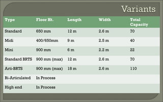

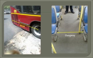


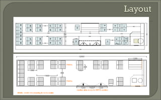
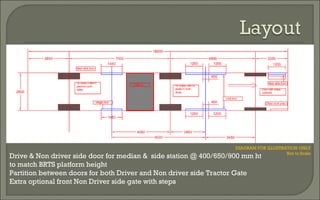
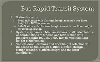
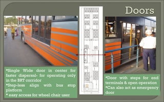
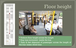
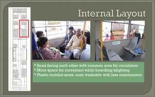
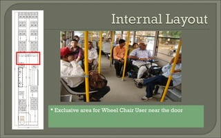
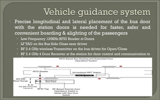
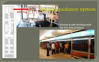


This document discusses recommendations for standardizing urban bus specifications in India. It proposes the following: 1. Uniform internal floor height of 400mm, 650mm, or 900mm without steps to improve accessibility and passenger movement. 2. Door locations and widths of at least 700mm to align with median or side platforms and allow fast boarding and alighting. 3. Technical specifications for improved passenger experience including pneumatic doors, wider gangways, health monitoring systems, and precision docking with stations. 4. Encouragement of local bus body manufacturers and standard testing to ensure quality, affordability and fuel efficiency of buses.


