Transformer Voltage Regulation
andEfficiency
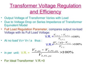
• Output Voltage of Transformer Varies with Load
• Due to Voltage Drop on Series Impedance of Transformer
Equivalent Model
• Full Load Regulation Parameter, compares output no-load
Voltage with its Full Load Voltage:
V.R. =
• At no load VS= VP / a thus :
V.R.=
• in per unit: V.R. =
• For Ideal Transformer V.R.=0
%
100
.
.
,
.
.
,
.
.
,
L
F
S
L
F
S
L
N
S
V
V
V
%
100
)
/
(
.
.
.
.
L
F
L
F
P
V
V
a
V
%
100
,
,
,
,
,
pu
FL
S
pu
FL
S
pu
P
V
V
V
3.
Transformer Voltage Regulationand
Efficiency
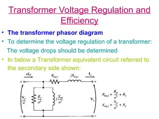
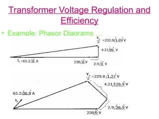
• The transformer phasor diagram
• To determine the voltage regulation of a transformer:
The voltage drops should be determined
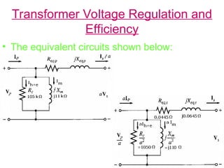
• In below a Transformer equivalent circuit referred to
the secondary side shown:
4.
Transformer Voltage Regulation
andEfficiency
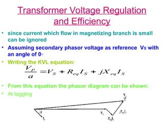
• since current which flow in magnetizing branch is small
can be ignored
• Assuming secondary phasor voltage as reference VS with
an angle of 0◦
• Writing the KVL equation:
• From this equation the phasor diagram can be shown:
• At lagging power factor:
S
eq
S
eq
S
P
I
jX
I
R
V
a
V
5.
Transformer Voltage Regulationand
Efficiency
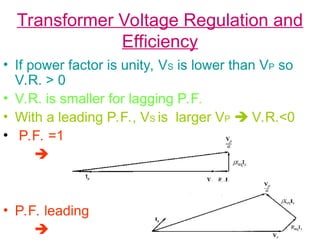
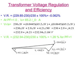
• If power factor is unity, VS is lower than VP so
V.R. > 0
• V.R. is smaller for lagging P.F.
• With a leading P.F., VS is larger VP V.R.<0
• P.F. =1
• P.F. leading
6.
Transformer Voltage Regulation
andEfficiency
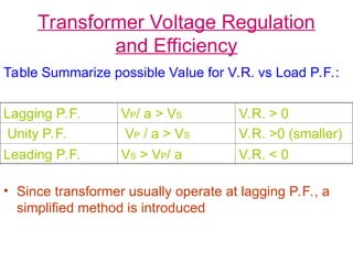
Table Summarize possible Value for V.R. vs Load P.F.:
• Since transformer usually operate at lagging P.F., a
simplified method is introduced
Lagging P.F. VP/ a > VS V.R. > 0
Unity P.F. VP / a > VS V.R. >0 (smaller)
Leading P.F. VS > VP/ a V.R. < 0
7.
Transformer Voltage Regulationand
Efficiency
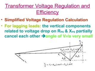
• Simplified Voltage Regulation Calculation
• For lagging loads: the vertical components
related to voltage drop on Req & Xeq partially
cancel each other angle of VP/a very small
8.
Transformer Voltage Regulation
andEfficiency
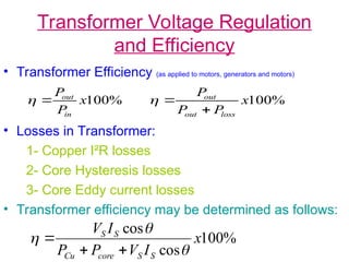
• Transformer Efficiency (as applied to motors, generators and motors)
• Losses in Transformer:
1- Copper I²R losses
2- Core Hysteresis losses
3- Core Eddy current losses
• Transformer efficiency may be determined as follows:
%
100
x
P
P
in
out
%
100
x
P
P
P
loss
out
out
%
100
cos
cos
x
I
V
P
P
I
V
S
S
core
Cu
S
S
9.
Transformer Voltage Regulation
andEfficiency
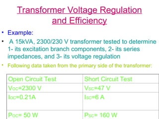
• Example:
• A 15kVA, 2300/230 V transformer tested to determine
1- its excitation branch components, 2- its series
impedances, and 3- its voltage regulation
• Following data taken from the primary side of the transformer:
Open Circuit Test Short Circuit Test
VOC=2300 V VSC=47 V
IOC=0.21A ISC=6 A
POC= 50 W PSC= 160 W
10.
Transformer Voltage Regulation
andEfficiency
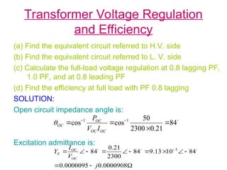
(a) Find the equivalent circuit referred to H.V. side
(b) Find the equivalent circuit referred to L. V. side
(c) Calculate the full-load voltage regulation at 0.8 lagging PF,
1.0 PF, and at 0.8 leading PF
(d) Find the efficiency at full load with PF 0.8 lagging
SOLUTION:
Open circuit impedance angle is:
Excitation admittance is:
84
21
.
0
2300
50
cos
cos 1
1
OC
OC
OC
OC
I
V
P
0000908
.
0
0000095
.
0
84
10
13
.
9
84
2300
21
.
0
84 5
j
V
I
Y
OC
OC
E
11.
Transformer Voltage Regulation
andEfficiency
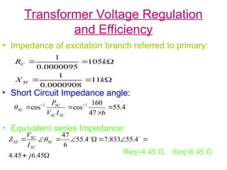
• Impedance of excitation branch referred to primary:
• Short Circuit Impedance angle:
• Equivalent series Impedance:
Req=4.45 Ω, Xeq=6.45 Ω
k
X
k
R
M
C
11
0000908
.
0
1
105
0000095
.
0
1
4
.
55
6
47
160
cos
cos 1
1
SC
SC
SC
SC
I
V
P
45
.
6
45
.
4
4
.
55
833
.
7
4
.
55
6
47
j
I
V
Z SC
SC
SC
SE
Transformer Voltage Regulationand
Efficiency
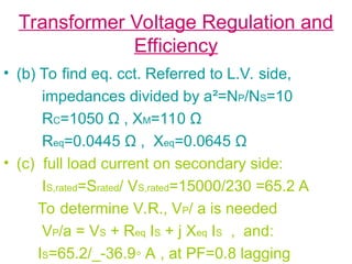
• (b) To find eq. cct. Referred to L.V. side,
impedances divided by a²=NP/NS=10
RC=1050 Ω , XM=110 Ω
Req=0.0445 Ω , Xeq=0.0645 Ω
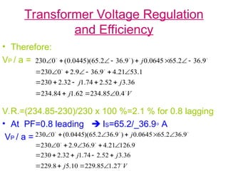
• (c) full load current on secondary side:
IS,rated=Srated/ VS,rated=15000/230 =65.2 A
To determine V.R., VP/ a is needed
VP/a = VS + Req IS + j Xeq IS , and:
IS=65.2/_-36.9◦ A , at PF=0.8 lagging
Transformer Voltage Regulationand
Efficiency
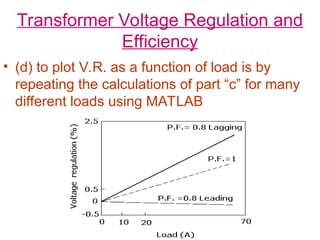
• (d) to plot V.R. as a function of load is by
repeating the calculations of part “c” for many
different loads using MATLAB
18.
Transformer Voltage Regulationand
Efficiency
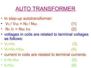
• (e) Efficiency of Transformer:
- Copper losses:
PCu=(IS)²Req =(65.2)² (0.0445)=189 W
- Core losses:
PCore= (VP/a)² / RC= (234.85)² / 1050=52.5 W
output power:
Pout=VSIS cosθ=230x65.2xcos36.9◦=12000 W
η= VSIS cosθ / [PCu+PCore+VSIS cosθ] x 100%=
12000/ [189+52.5+12000] = 98.03 %
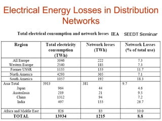
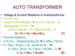
Energy Losses inElectrical Energy
Systems
• The total electrical energy use per annum of the world
is estimated as 13,934
• TeraWatthours [TWh] (1 TWh = 10^9 kWh)
• it is further estimated [2] that the losses in all of the
world’s electrical distribution systems total about
1215 TWh or
• about 8.8% of the total electrical energy consumed.
About 30-35% of these losses are generated in the
Transformers in the Distribution systems.
• Studies estimate that some 40-80% of these
transformer losses are potentially saveable by
increasing transformer efficiencies, i.e. 145-290 TWh.
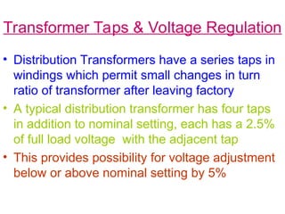
Transformer Taps &Voltage Regulation
• Distribution Transformers have a series taps in
windings which permit small changes in turn
ratio of transformer after leaving factory
• A typical distribution transformer has four taps
in addition to nominal setting, each has a 2.5%
of full load voltage with the adjacent tap
• This provides possibility for voltage adjustment
below or above nominal setting by 5%
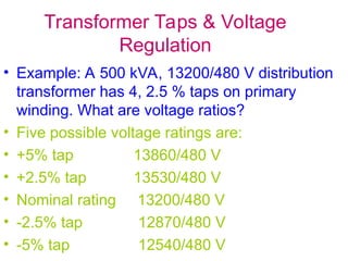
23.
Transformer Taps &Voltage
Regulation
• Example: A 500 kVA, 13200/480 V distribution
transformer has 4, 2.5 % taps on primary
winding. What are voltage ratios?
• Five possible voltage ratings are:
• +5% tap 13860/480 V
• +2.5% tap 13530/480 V
• Nominal rating 13200/480 V
• -2.5% tap 12870/480 V
• -5% tap 12540/480 V
24.
Transformer Taps &Voltage Regulation
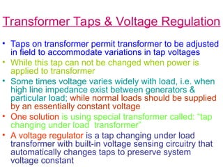
• Taps on transformer permit transformer to be adjusted
in field to accommodate variations in tap voltages
• While this tap can not be changed when power is
applied to transformer
• Some times voltage varies widely with load, i.e. when
high line impedance exist between generators &
particular load; while normal loads should be supplied
by an essentially constant voltage
• One solution is using special transformer called: “tap
changing under load transformer”
• A voltage regulator is a tap changing under load
transformer with built-in voltage sensing circuitry that
automatically changes taps to preserve system
voltage constant
25.
AUTO TRANSFORMER
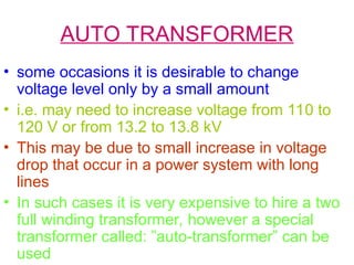
• someoccasions it is desirable to change
voltage level only by a small amount
• i.e. may need to increase voltage from 110 to
120 V or from 13.2 to 13.8 kV
• This may be due to small increase in voltage
drop that occur in a power system with long
lines
• In such cases it is very expensive to hire a two
full winding transformer, however a special
transformer called: ”auto-transformer” can be
used
AUTO TRANSFORMER
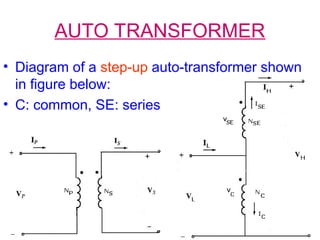
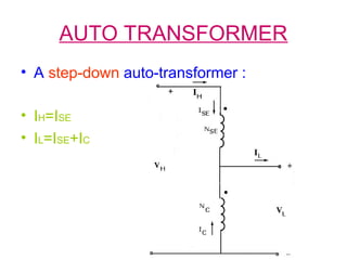
• Instep-up autotransformer:
• VC / VSE = NC / NSE (1)
• NC IC = NSE ISE (2)
• voltages in coils are related to terminal voltages
as follows:
• VL=VC (3)
• VH=VC+VSE (4)
• current in coils are related to terminal currents:
• IL=IC+ISE (5)
• IH=ISE (6)
29.
AUTO TRANSFORMER
• Voltage& Current Relations in Autotransformer
• VH=VC+VSE
• since VC/VSE=NC/NSE VH=VC+ NSE/NC . VC
• Noting that: VL=VC
VH=VL+ NSE/NC . VL= (NSE+NC)/NC . VL
• VL / VH = NC / (NSE+NC) (7)
• Current relations:
• IL=IC+ISE employing Eq.(2) IC=(NSE / NC)ISE
• IL= (NSE / NC)ISE + ISE, since ISE=IH
IL= (NSE / NC)IH +IH = (NSE + NC)/NC . IH
IL / IH = (NSE + NC)/NC (8)
30.
AUTO TRANSFORMER
• ApparentPower Rating Advantage of Autotransformer
• Note : not all power transferring from primary to
secondary in autotransformer pass through windings
• Therefore if a conventional transformer be
reconnected as an autotransformer, it can handle
much more power than its original rating
• The input apparent power to the step-up
autotransformer is : Sin=VLIL
• And the output apparent power is:
Sout=VH IH
31.
AUTO TRANSFORMER
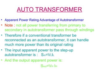
• And:
Sin=Sout=SIO
• Apparent power of transformer windings:
SW= VCIC=VSE ISE
• This apparent power can be reformulated:
SW= VCIC=VL(IL-IH) =VLIL-VLIH
• employing Eq.(8) SW= VLIL-VLIL NC/(NSE+NC)
=VLIL [(NSE+NC)-NC] /(NSE+NC)=SIO NSE /(NSE+NC)
SIO / SW = (NSE+NC) / NSE (9)
32.
AUTO TRANSFORMER
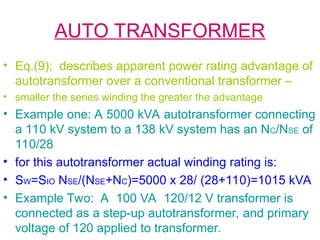
• Eq.(9);describes apparent power rating advantage of
autotransformer over a conventional transformer –
• smaller the series winding the greater the advantage
• Example one: A 5000 kVA autotransformer connecting
a 110 kV system to a 138 kV system has an NC/NSE of
110/28
• for this autotransformer actual winding rating is:
• SW=SIO NSE/(NSE+NC)=5000 x 28/ (28+110)=1015 kVA
• Example Two: A 100 VA 120/12 V transformer is
connected as a step-up autotransformer, and primary
voltage of 120 applied to transformer.
33.
AUTO TRANSFORMER
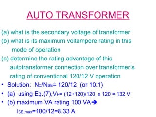
(a) whatis the secondary voltage of transformer
(b) what is its maximum voltampere rating in this
mode of operation
(c) determine the rating advantage of this
autotransformer connection over transformer’s
rating of conventional 120/12 V operation
• Solution: NC/NSE= 120/12 (or 10:1)
• (a) using Eq.(7),VH= (12+120)/120 x 120 = 132 V
• (b) maximum VA rating 100 VA
ISE,max=100/12=8.33 A
34.
AUTO TRANSFORMER
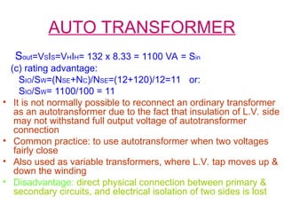
Sout=VSIS=VHIH= 132x 8.33 = 1100 VA = Sin
(c) rating advantage:
SIO/SW=(NSE+NC)/NSE=(12+120)/12=11 or:
SIO/SW= 1100/100 = 11
• It is not normally possible to reconnect an ordinary transformer
as an autotransformer due to the fact that insulation of L.V. side
may not withstand full output voltage of autotransformer
connection
• Common practice: to use autotransformer when two voltages
fairly close
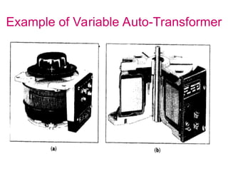
• Also used as variable transformers, where L.V. tap moves up &
down the winding
• Disadvantage: direct physical connection between primary &
secondary circuits, and electrical isolation of two sides is lost
35.
AUTO TRANSFORMER
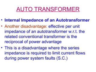
• InternalImpedance of an Autotransformer
• Another disadvantage: effective per unit
impedance of an autotransformer w.r.t. the
related conventional transformer is the
reciprocal of power advantage
• This is a disadvantage where the series
impedance is required to limit current flows
during power system faults (S.C.)
36.
AUTO TRANSFORMER
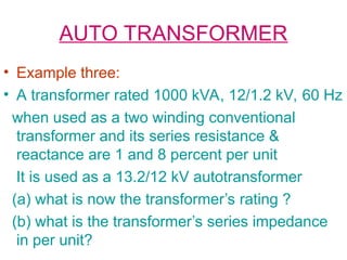
• Examplethree:
• A transformer rated 1000 kVA, 12/1.2 kV, 60 Hz
when used as a two winding conventional
transformer and its series resistance &
reactance are 1 and 8 percent per unit
It is used as a 13.2/12 kV autotransformer
(a) what is now the transformer’s rating ?
(b) what is the transformer’s series impedance
in per unit?
37.
AUTO TRANSFORMER
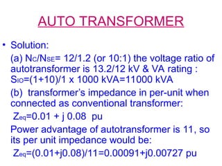
• Solution:
(a)NC/NSE= 12/1.2 (or 10:1) the voltage ratio of
autotransformer is 13.2/12 kV & VA rating :
SIO=(1+10)/1 x 1000 kVA=11000 kVA
(b) transformer’s impedance in per-unit when
connected as conventional transformer:
Zeq=0.01 + j 0.08 pu
Power advantage of autotransformer is 11, so
its per unit impedance would be:
Zeq=(0.01+j0.08)/11=0.00091+j0.00727 pu

![Transformer Voltage Regulation and
Efficiency
• (e) Efficiency of Transformer:
- Copper losses:
PCu=(IS)²Req =(65.2)² (0.0445)=189 W
- Core losses:
PCore= (VP/a)² / RC= (234.85)² / 1050=52.5 W
output power:
Pout=VSIS cosθ=230x65.2xcos36.9◦=12000 W
η= VSIS cosθ / [PCu+PCore+VSIS cosθ] x 100%=
12000/ [189+52.5+12000] = 98.03 %](https://image.slidesharecdn.com/25471energyconversion6-250311054057-60451557/85/25471_ENERGY_CONVERSION-for-energy-audit_6-ppt-18-320.jpg)
![Energy Losses in Electrical Energy
Systems
• The total electrical energy use per annum of the world
is estimated as 13,934
• TeraWatthours [TWh] (1 TWh = 10^9 kWh)
• it is further estimated [2] that the losses in all of the
world’s electrical distribution systems total about
1215 TWh or
• about 8.8% of the total electrical energy consumed.
About 30-35% of these losses are generated in the
Transformers in the Distribution systems.
• Studies estimate that some 40-80% of these
transformer losses are potentially saveable by
increasing transformer efficiencies, i.e. 145-290 TWh.](https://image.slidesharecdn.com/25471energyconversion6-250311054057-60451557/85/25471_ENERGY_CONVERSION-for-energy-audit_6-ppt-20-320.jpg)
![AUTO TRANSFORMER
• And :
Sin=Sout=SIO
• Apparent power of transformer windings:
SW= VCIC=VSE ISE
• This apparent power can be reformulated:
SW= VCIC=VL(IL-IH) =VLIL-VLIH
• employing Eq.(8) SW= VLIL-VLIL NC/(NSE+NC)
=VLIL [(NSE+NC)-NC] /(NSE+NC)=SIO NSE /(NSE+NC)
SIO / SW = (NSE+NC) / NSE (9)](https://image.slidesharecdn.com/25471energyconversion6-250311054057-60451557/85/25471_ENERGY_CONVERSION-for-energy-audit_6-ppt-31-320.jpg)