This document discusses the estimation of very fast transient overvoltages (VFTOs) in a 3-phase 132kV gas insulated substation (GIS). It presents the modeling of a GIS system in MATLAB to analyze VFTOs generated during switching operations and 3-phase faults. Each re-strike of the disconnector switch during opening/closing generates high frequency transient overvoltages that can damage equipment. The paper develops an accurate electrical model of the GIS components using lumped parameters to simulate transient behavior and calculate overvoltage waveforms.
![ISSN: 2278 – 1323
International Journal of Advanced Research in Computer Engineering & Technology
Volume 1, Issue 4, June 2012
Estimation of Re-striking Transient Overvoltages
in a 3-Phase 132KV Gas insulated Substation
M. Kondalu1, Dr. P.S. Subramanyam2
Electrical & Electronics Engineering, JNT University. Hyderabad.
1
Kondalu_m@yahoo.com
Joginpally B.R. Engineering College, Hyderabad
2
subramanyamps@gmail.com
VBIT, Ghatkesar,Hyderabad
Abstract: --This paper presents the most significant results of a A GIS system comprising of an Input Cable, Spacer,
Very fast transient Overvoltages generated due to switching Dis-connector Switch, Bus bar of 10mts length and load has
operations have been analyzed and presented. Since the contact been considered for modelling into electrical network and
speed of dis-connector switches is low, re-striking occurs many analysis [6]. The Fast Transient Over voltage waveform
times before the current interruption is completed .Each re-
striking generates transient overvoltage with level of magnitude.
generated during Closing and Opening operation of Dis-
These transient have travelling wave behaviour, they travel to connector Switch and 3-phase faults has been considered for
the external systems through enclosures, bushings, cable joints calculations.
etc.. and cause damage to the outside equipment. They can lead Spacers are simulated by lumped Capacitance. The
secondary break downs in GIS and may give rise to Inductance of the bus duct is calculated from the diameters of
electromagnetic interference. The Earth faults give rise to TEV Conductor and Enclosure. Capacitances are calculated on the
which can interfere with the operation and control of secondary basis of actual diameters of inner and outer cylinders of
equipment in a 3-phase 132kv GIS. Thus it is important to central conductor and outer enclosure [7]. Cone Insulators
develop a suitable MATLAB7.8 models for estimation of these used for supporting inner conductor against outer enclosure
overvoltages. are assumed to be disk type for approximate calculation of
Keywords—Gas Insulated Substation (GIS), very fast Transient
spacer capacitance [8].
overvoltages, 3phase faults, MATLAB 7.8 software and Control
circuitry The busduct can be modelled as a series of Pi-
network or as sequence parameters. However in this model, it
I. INTRODUCTION is considered as distributed Pi-network. The Schematic
For accurate analysis of transients, it is essential to Diagram of a Typical Gas Insulated System (GIS) is shown in
find the VFTO‘s and circuit parameters. Due to the travelling below figure 3.
nature of the transients the modelling of GIS makes use of
electrical equivalent circuits composed by lumped elements Frequency nature, the VFTO imposed on the transformers
and especially by distributed parameter lines, surge connected directly to the GIS would not be distributed evenly
impedances and travelling times. The simulation depends on on all transformer windings. Some windings, e.g. the first few
the quality of the model of each individual GIS component [1]. turns connecting to the 132kV GIS, would be subject to a
In order to achieve reasonable results in GIS structures highly higher magnitude of overvoltage, posing a potential risk of
accurate models for each internal equipment and also for insulation breakdown of the transformers[9][10].
components connected to the GIS are necessary [2].
II. MODELLING OF 132KV GAS INSULATED SUBSTATION:
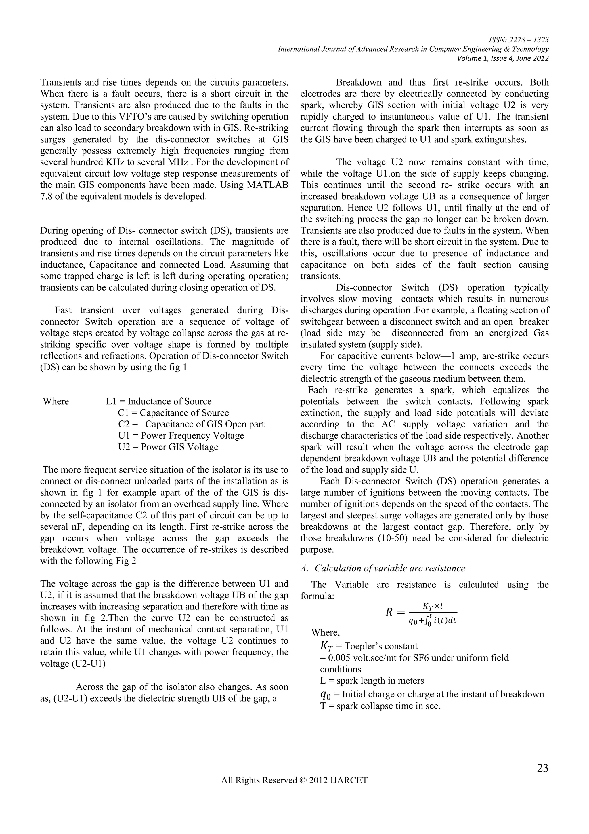
The dis-connector spark itself has to be taken into During the current operation of dis-connector switch in a GIS,
account by transient resistance according to the Toepler‘s re-strikes(pre-strikes) occur because of low speed of the dis-
equation and subsequent arc resistance of a few ohms [3][4]. connector switch moving contact, hence Very fast Transient
The wave shape of the over voltage surge due to dis-connector Over voltage are developed. These VFTO‘s are caused by
switch is affected by all GIS elements. Accordingly, the switching operations and 3-phase fault
simulation of transients in GIS assumes an establishment of When a dis-connector switch is opened on a floating
the models for the Bus, Bushing, Elbow, Transformers, Surge section of switchgear, trapped charge may be left on the
Arresters, Breakers, Spacers, dis-connectors, and Enclosures floating section. In the opening operation of dis-connector
and so on[5]. switch, transients are produced and the magnitude of these
22
All Rights Reserved © 2012 IJARCET](https://image.slidesharecdn.com/22-27-120630093000-phpapp01/75/22-27-1-2048.jpg)


![ISSN: 2278 – 1323
International Journal of Advanced Research in Computer Engineering & Technology
Volume 1, Issue 4, June 2012
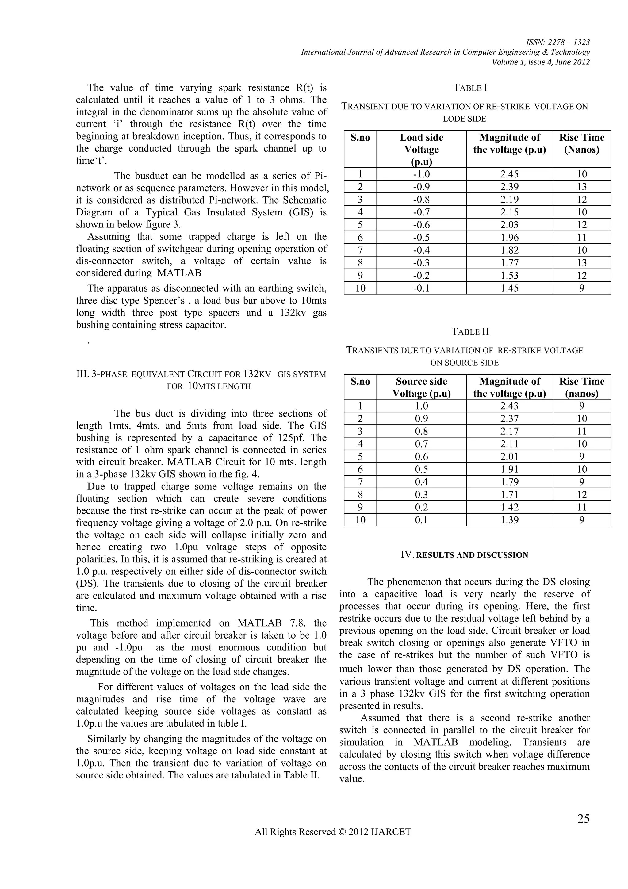
using standard formulae. Cone insulators used for
supporting inner conductor against outer enclosure are
assumed to be disk type for approximate calculation of
spacer capacitance is calculated using formulae for
concentric cylinders. The entire bus length is modelled as
distributed pi-network. The peak magnitude of fast
transient currents generated during switching event
changes from one position to another in a 132kv GIS for a
particular switching operation. These transients over
voltages are reduced by connecting suitable resistor in an
equivalent circuit during closing and opening operation.
VI. REFERENCES
[1] S.Ogawa, E. Haginomori, S. Nishiwaki, T.Yoshida,
K. Terasaka,―Estimation of Re-striking Transient Over Voltage
on Disconnecting Switch for GIS”, IEEE Trans. on PS, Vol.
PWRD-1, No-2, April 1986, pp.95-101
[2] Li Liu-ling, Hu Pan-feng, Qiu Yu-chang, Analysis of
Very Fast Transient Overvoltage Calculation Affected
by Different Transformer Winding Models, Journal
of Xi‘an Jiaotong University, 2005(10) Vol.39
No.10:1160-1164.
[3] Yang Linghui, Zhang Jiamin, Research on transient
Overvoltage during operation of 500kV GIS
Disconnecting switch, East China Electric Power, Jan.2004,
Vol.32 No.1:37-41
[4] Shibuya Y, Fujita S, Shimomura T. Effects of very
fast transient over- Voltages on Transformer [J].IEE
Proceedings, Part C,1999,146(4): 459-464.
[5] H. Hiesinger, RWitzmann. Very fast Transient
Breakdown at a needle Shaped Protrusion, IX Int.
Conf. on Gas Dis. and Their Applied. Sep 1988.
[6] MohanaRao M., Naidu M.S. (199% 'Estimation of
Fast Transient Overvoltages in the case of
Disconnnector operation in a GIS', 3d workshop & conference
on EHV Technology, IISC Bangalore.
[7] J.B. Kim,M.S. Kim,K.S.Park, W.P.Son.,.D.S. Kim,
G.S. Kil. Development of monitoring and diagnostic
System for SF6 gas insulated switchgear.
IEEE Conference Record of the 2002 IEEE
International Symposium on Electrical Insulation.
Boston, Massachusetts, UnitedStates, pp.453-456, 2002.
[8] M.kondalu, G.Sreekanthreddy, Dr. P.S. subramanyam,‖
Estimation Transientover voltages in gas insulated bus
duct from 220kv gas insulated substation‖,
International journal of Computer
Applications, (0975-8887) volume 20-no.8 April 2011.
[9] M.kondalu, G.Sreekanthreddy,Dr. P.S. subramanyam,‖
Analysis and Calculation of very fast transient over
Voltages in 220kv gas insulated substation international
Journal of Engineering& techscience vol 2(4) 2011
[10] D. Povh, H. Schmitt, O. Volcker, R. Witzmann,
―Modelling and Analysis Guidelines for Very Fast
Transients‖. IEEE Trans. on PD, Vol.11 No.4,
October 1996, pp.2028-2035.
27
All Rights Reserved © 2012 IJARCET](https://image.slidesharecdn.com/22-27-120630093000-phpapp01/75/22-27-6-2048.jpg)


![11.[21 28]voltage stability improvement using the 21st century power transformer](https://cdn.slidesharecdn.com/ss_thumbnails/11-21-28voltagestabilityimprovementusingthe21stcenturypowertransformer-120512235611-phpapp01-thumbnail.jpg?width=640&height=640&fit=bounds)


![3.[18 22]hybrid association rule mining using ac tree](https://cdn.slidesharecdn.com/ss_thumbnails/3-18-22hybridassociationruleminingusingactree-111203185002-phpapp01-thumbnail.jpg?width=640&height=640&fit=bounds)


![2.[6 13]investigation on d-statcom operation for power quality improvement in...](https://cdn.slidesharecdn.com/ss_thumbnails/2-6-13investigationond-statcomoperationforpowerqualityimprovementinathreephasethreewiredistributionsystemwithanewcontrolstrategy-111203184845-phpapp02-thumbnail.jpg?width=640&height=640&fit=bounds)


![Coded Agents – with UiPath SDK + LangGraph [Virtual Hands-on Workshop]](https://cdn.slidesharecdn.com/ss_thumbnails/codedagentsdeck-251215155422-5497c599-thumbnail.jpg?width=640&height=640&fit=bounds)


