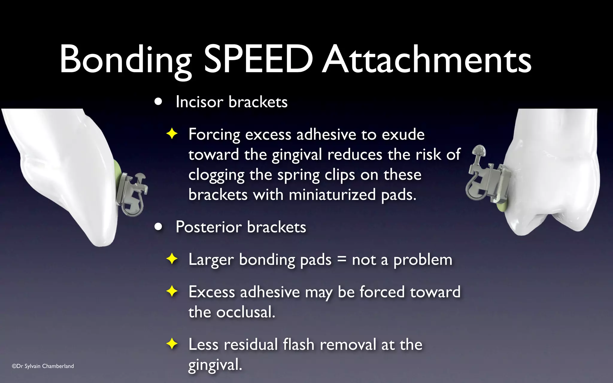
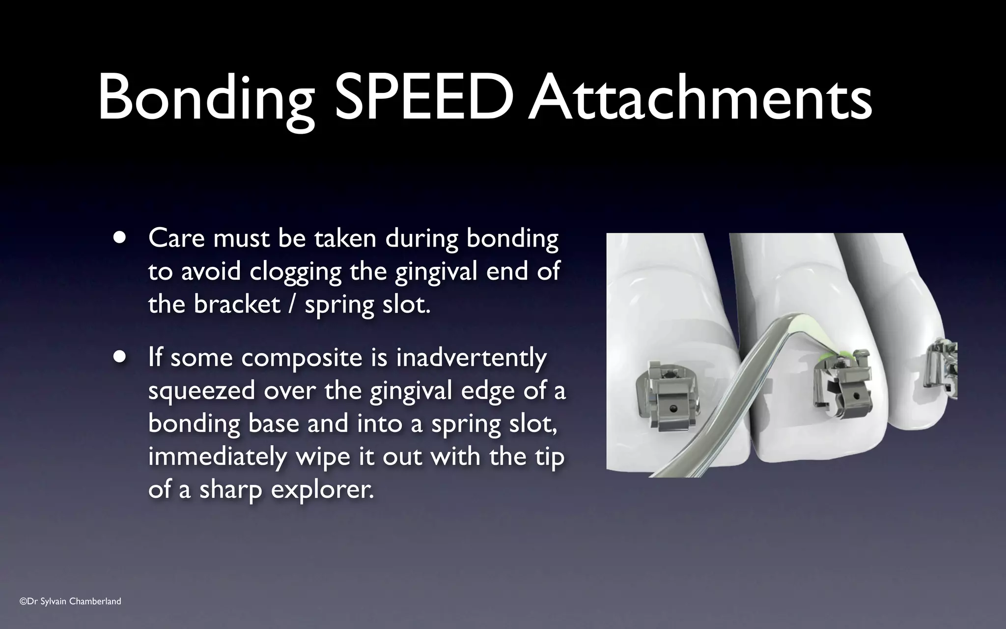
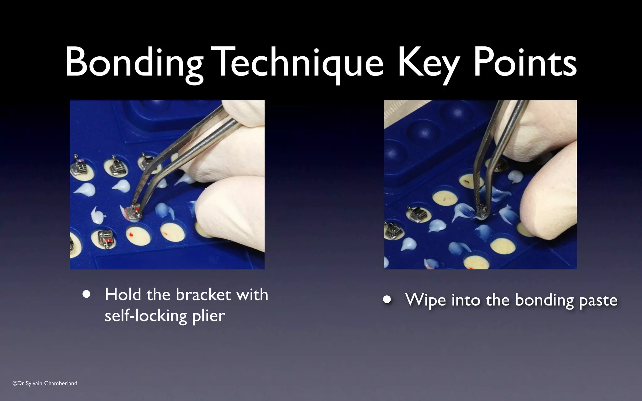
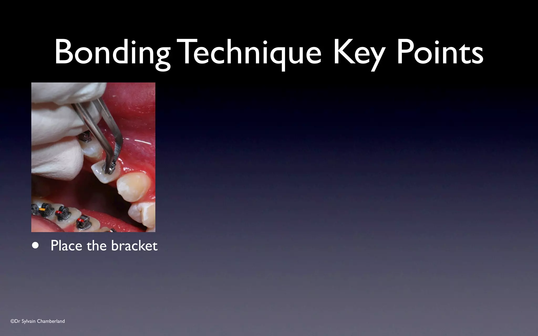
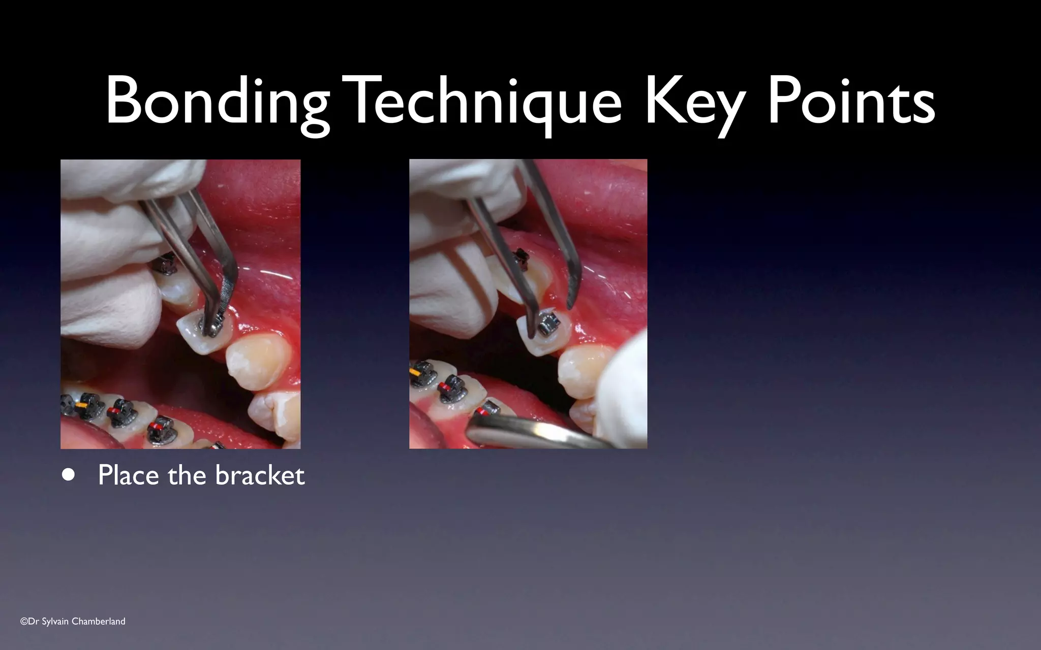
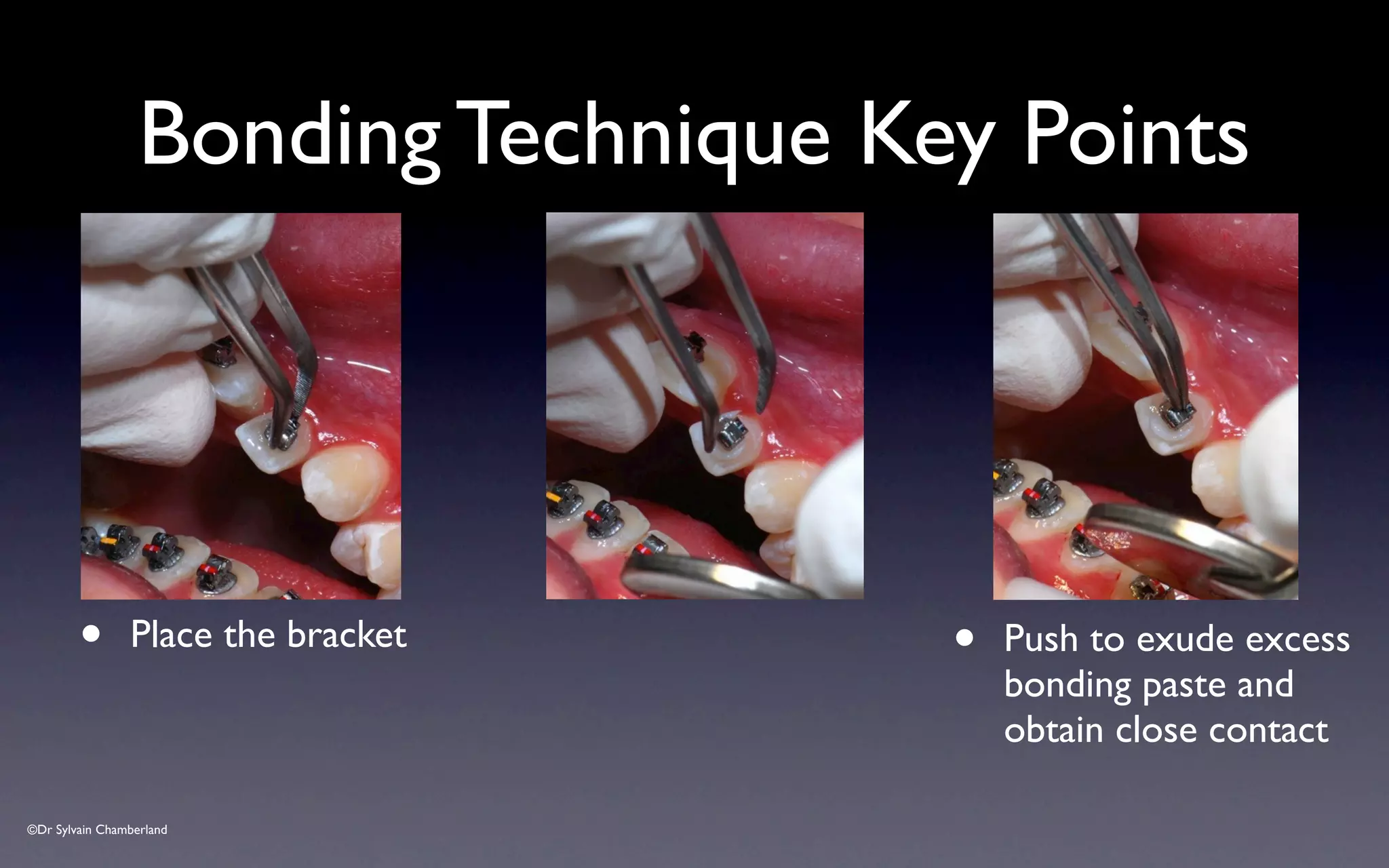
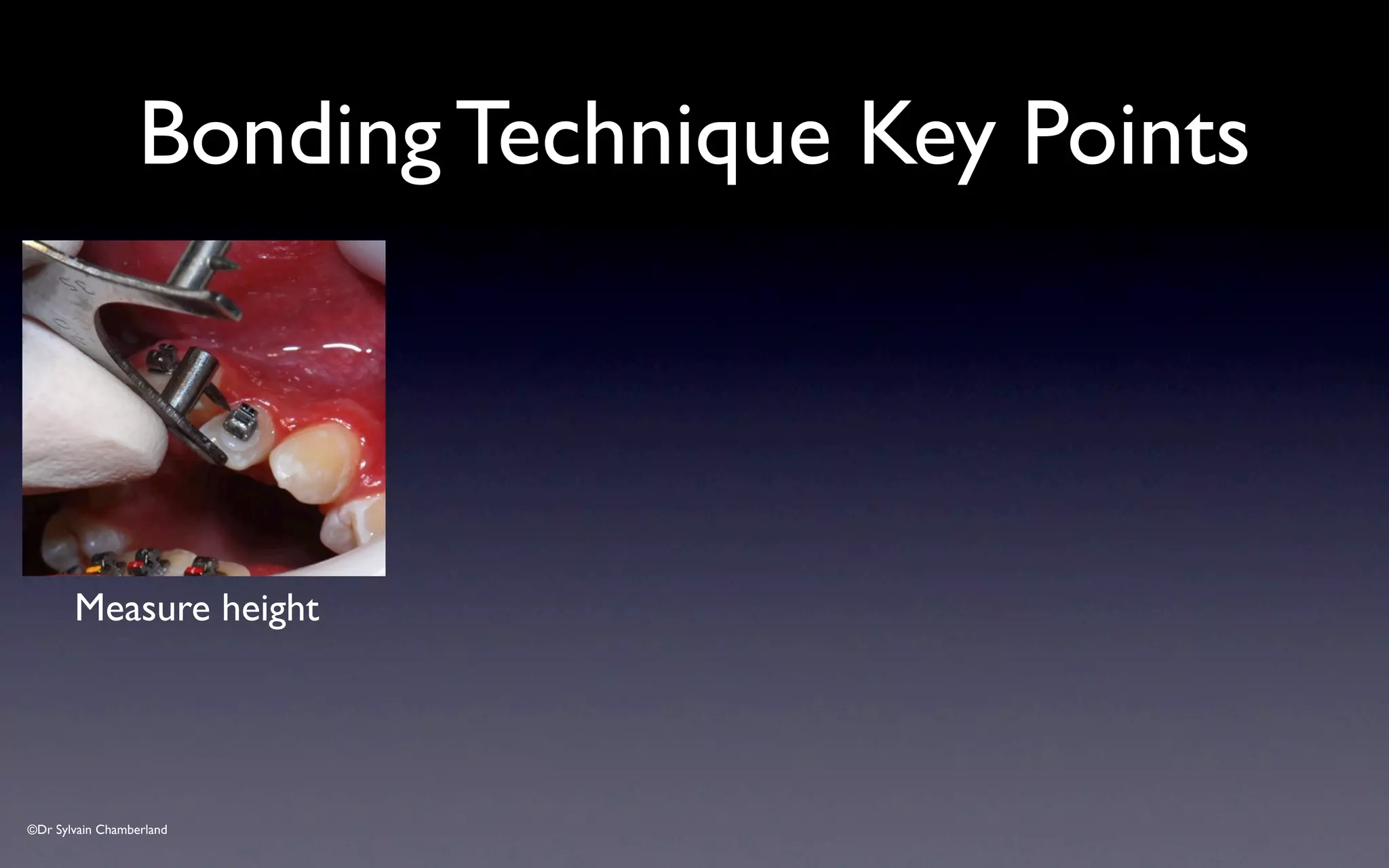
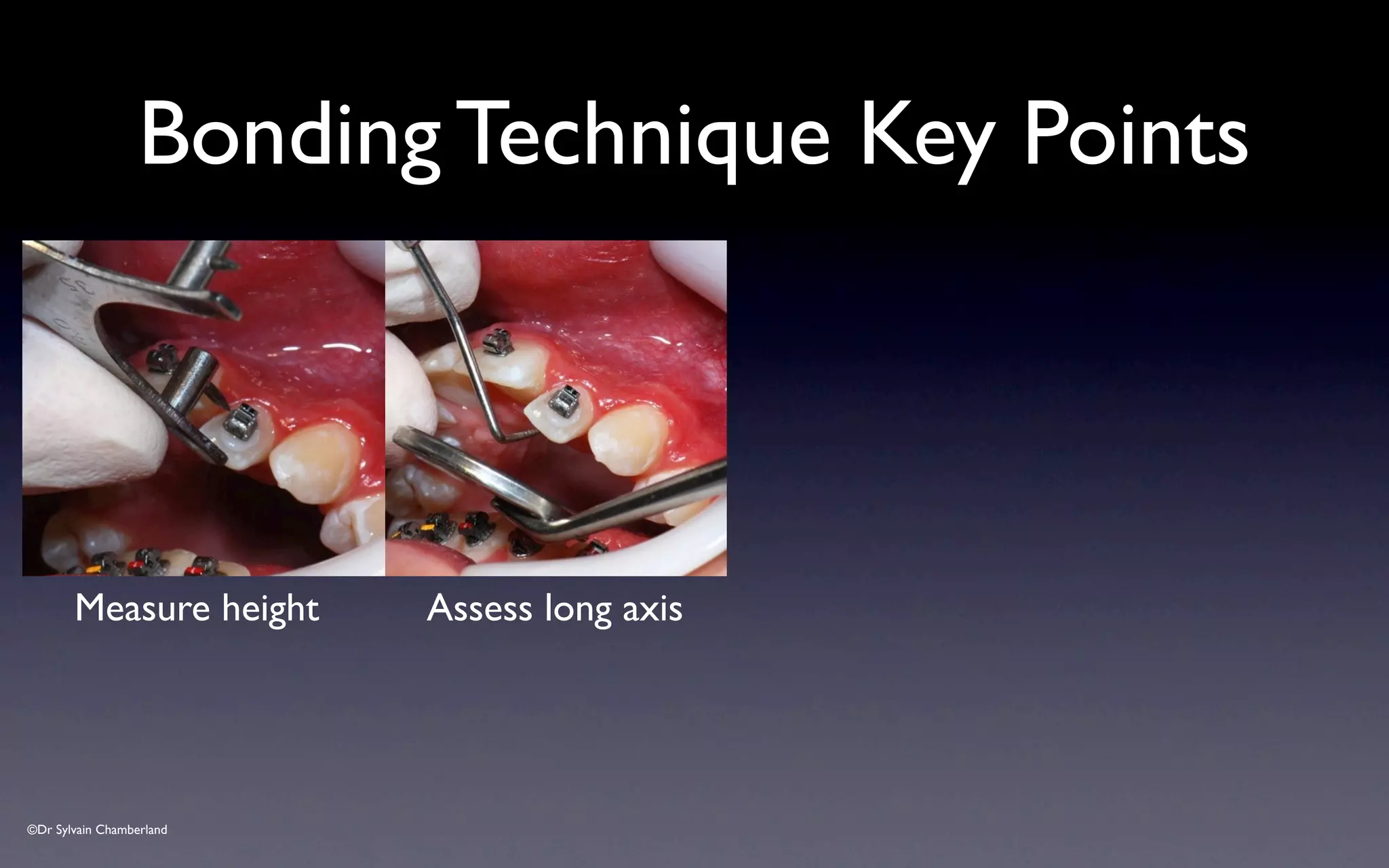
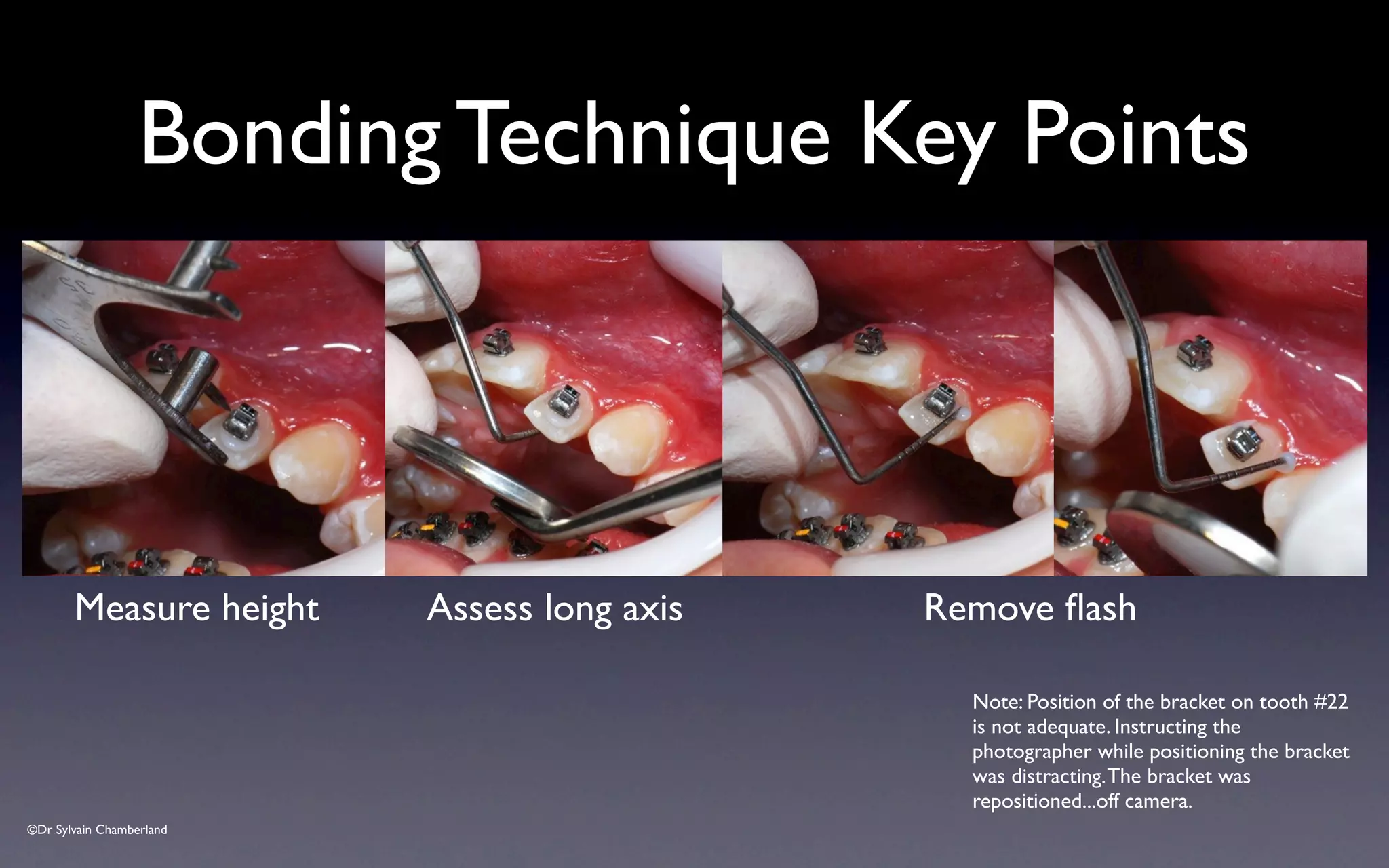
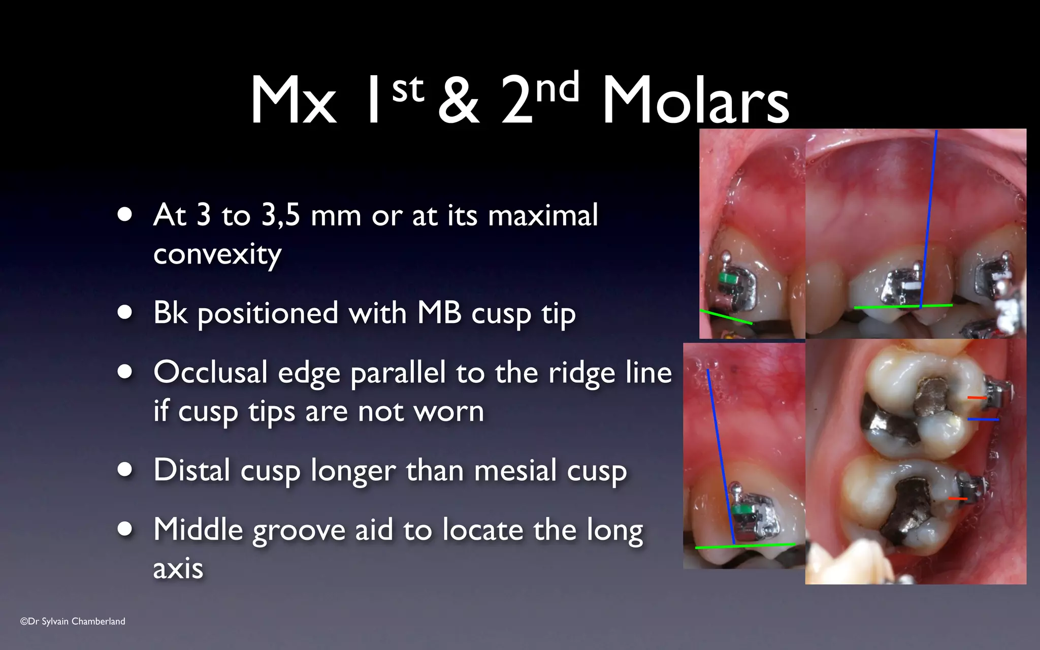
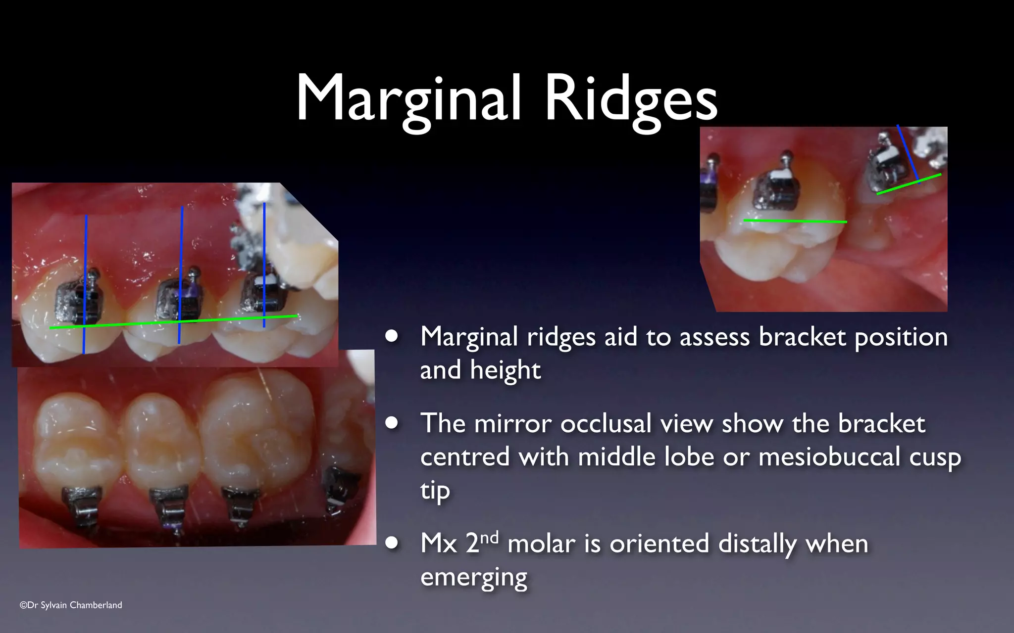
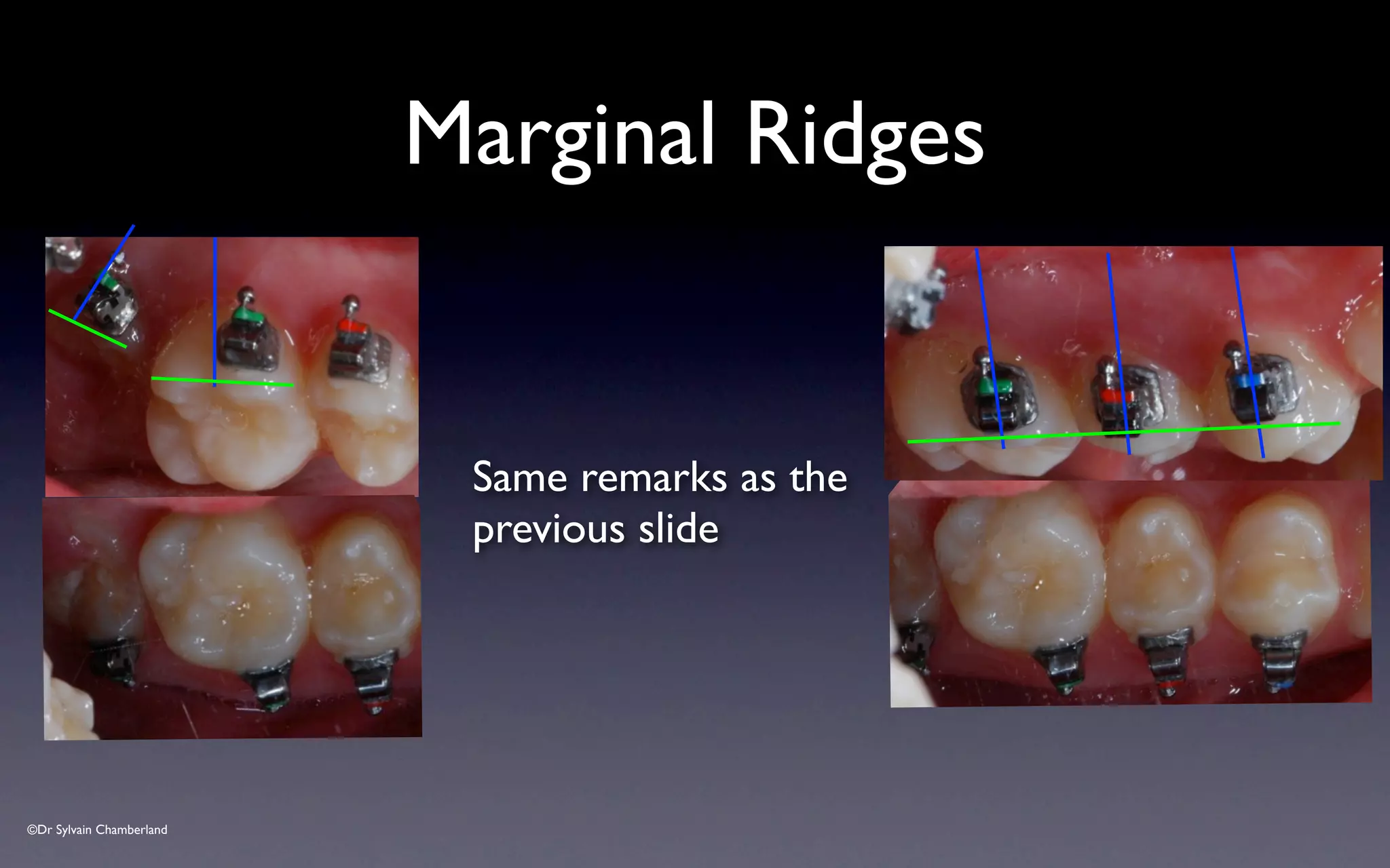
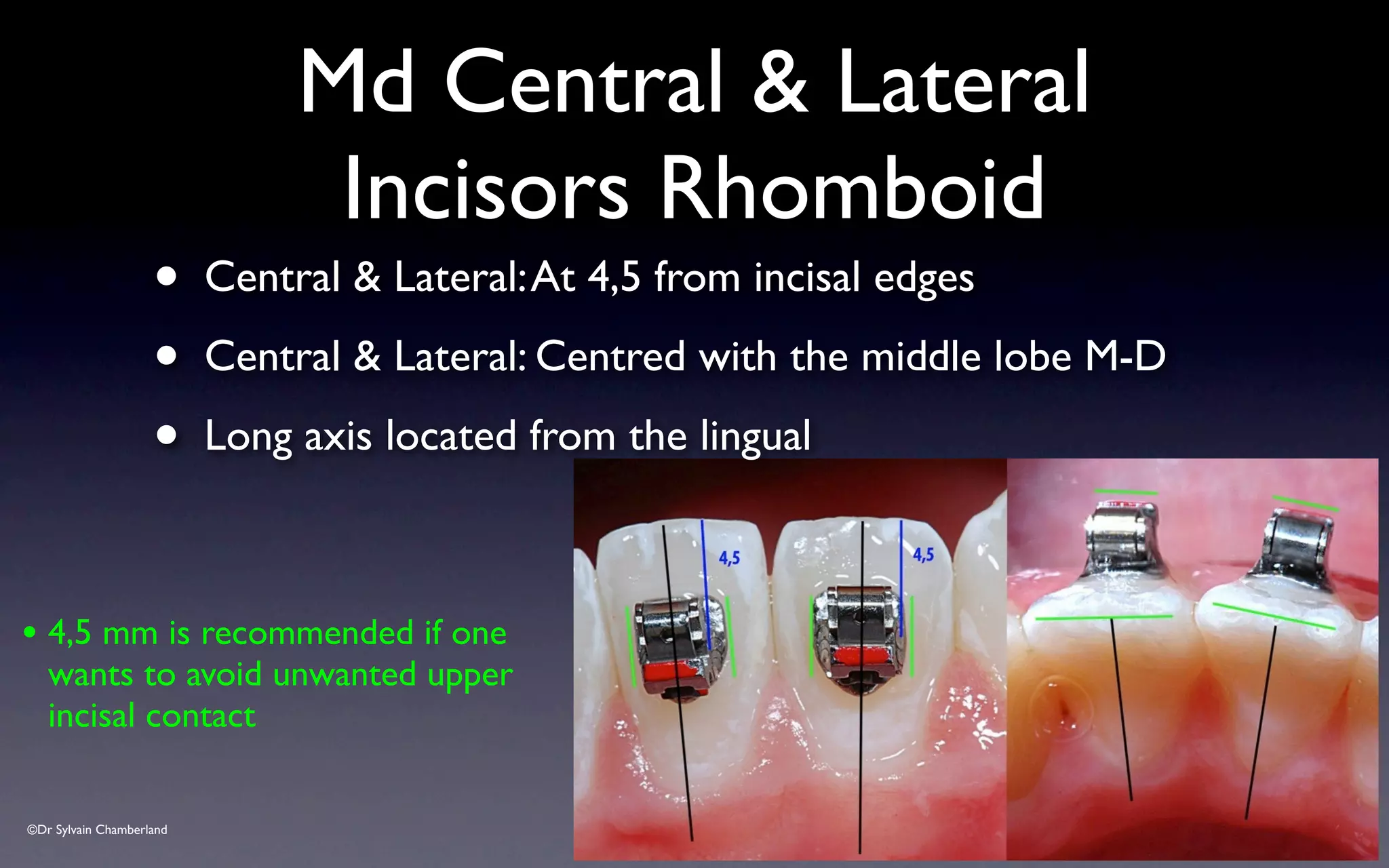
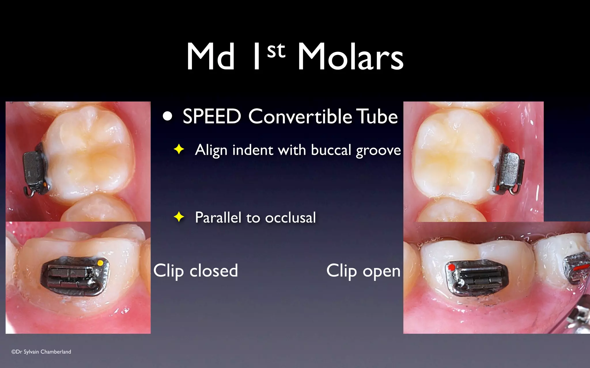
This document provides guidelines for proper placement of SPEED brackets. Key points include:
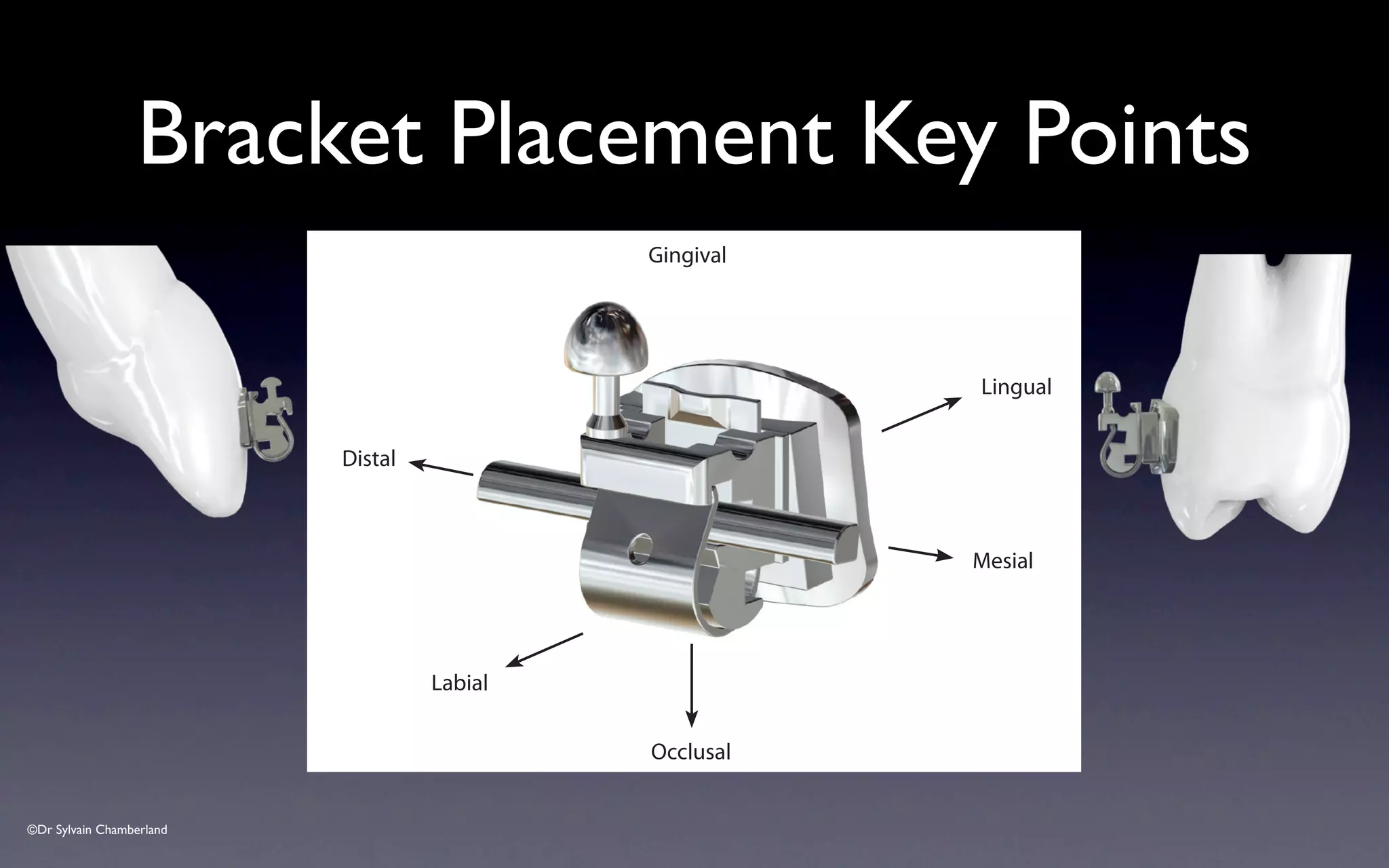
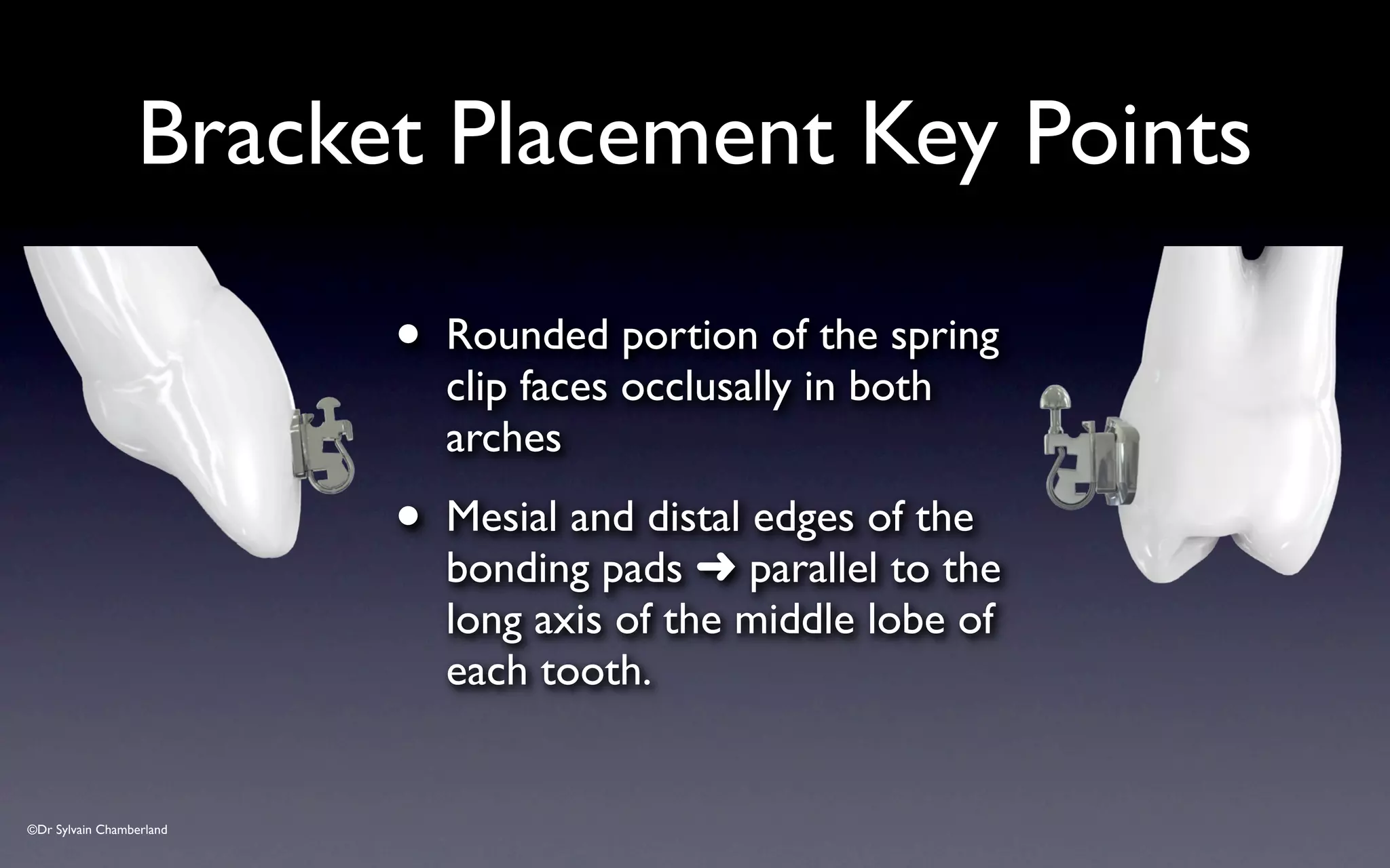
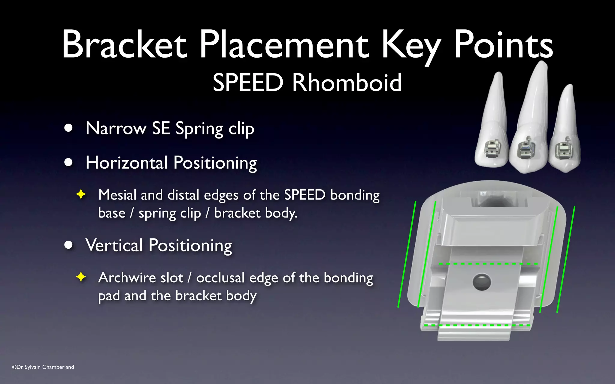
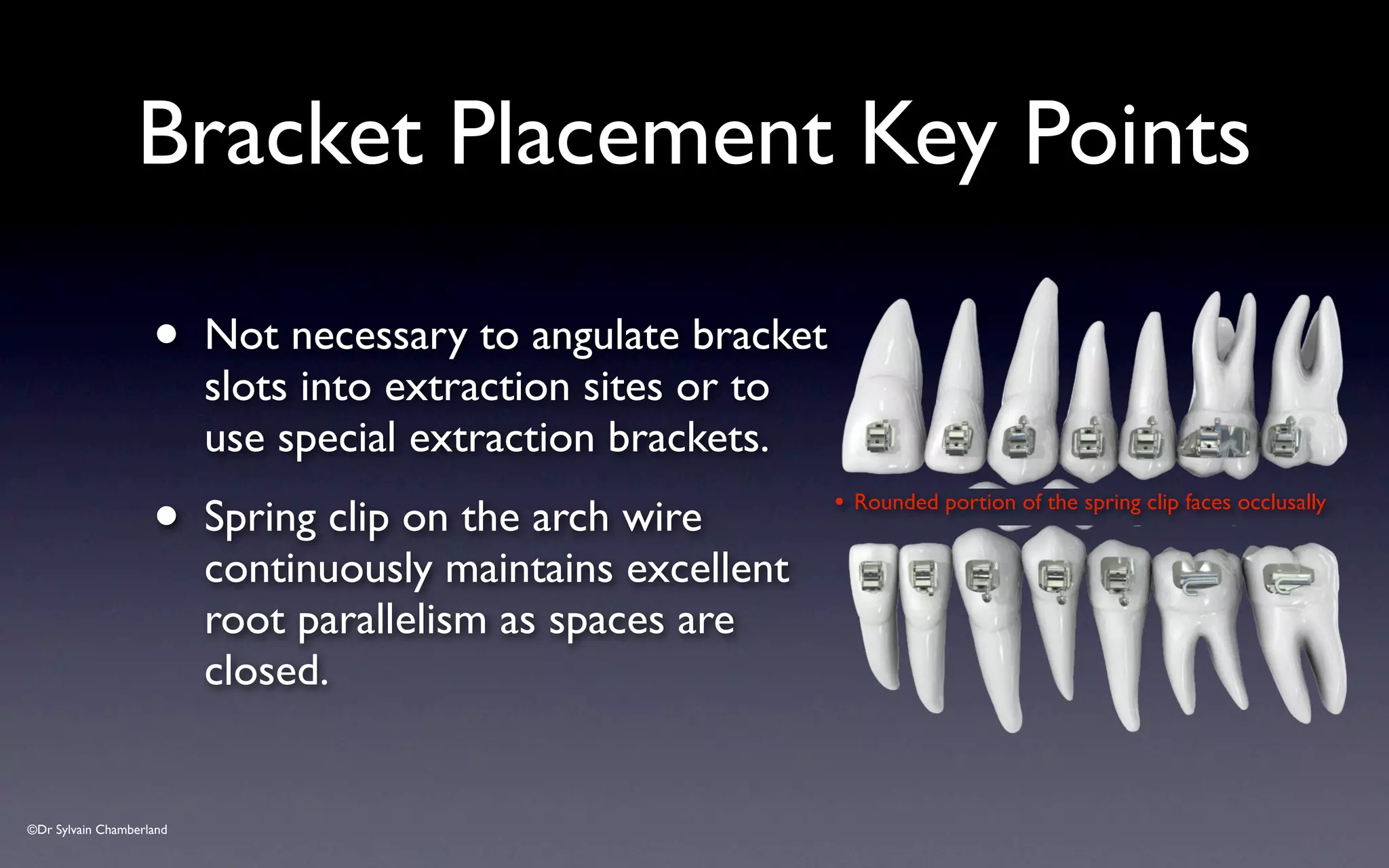
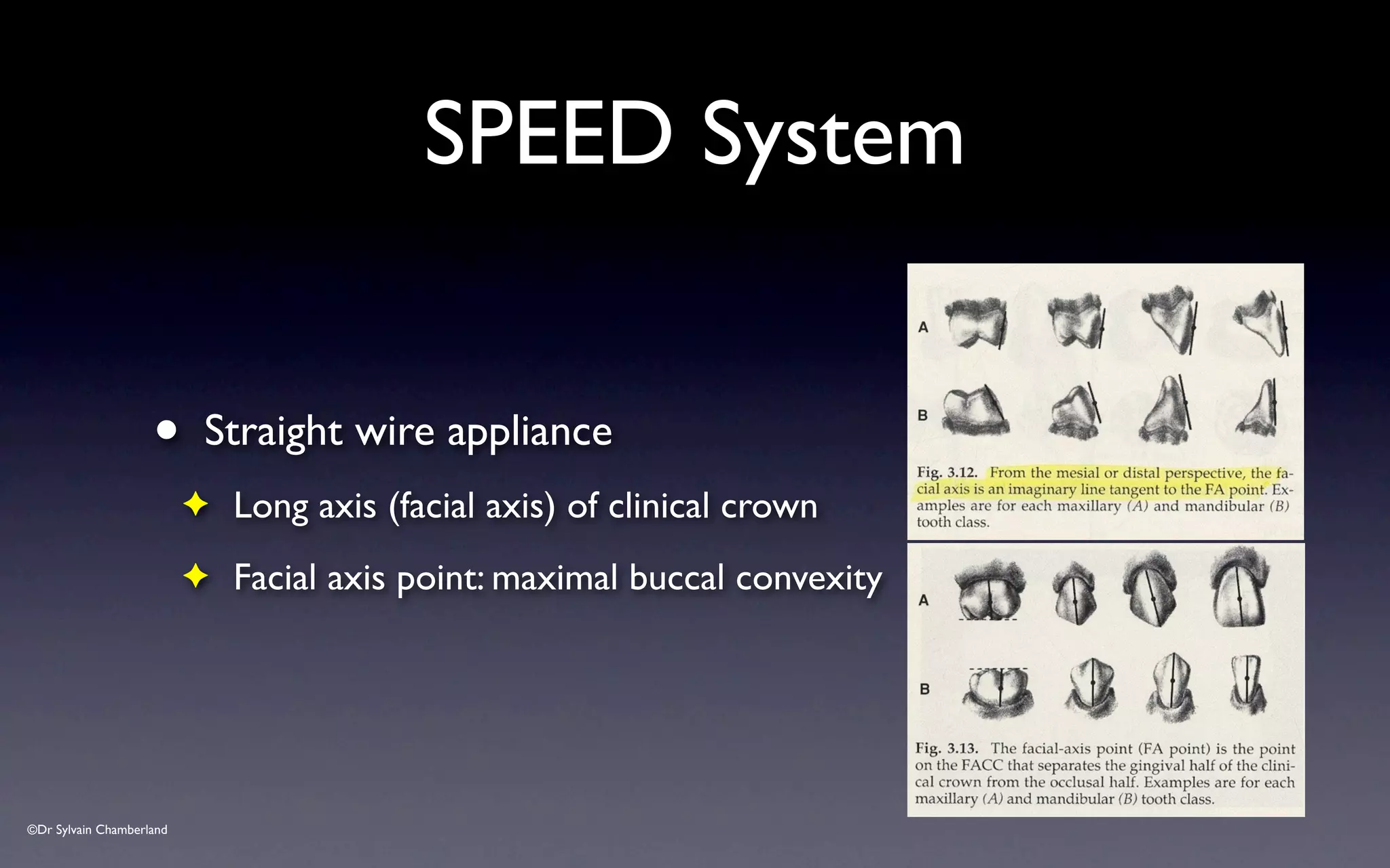
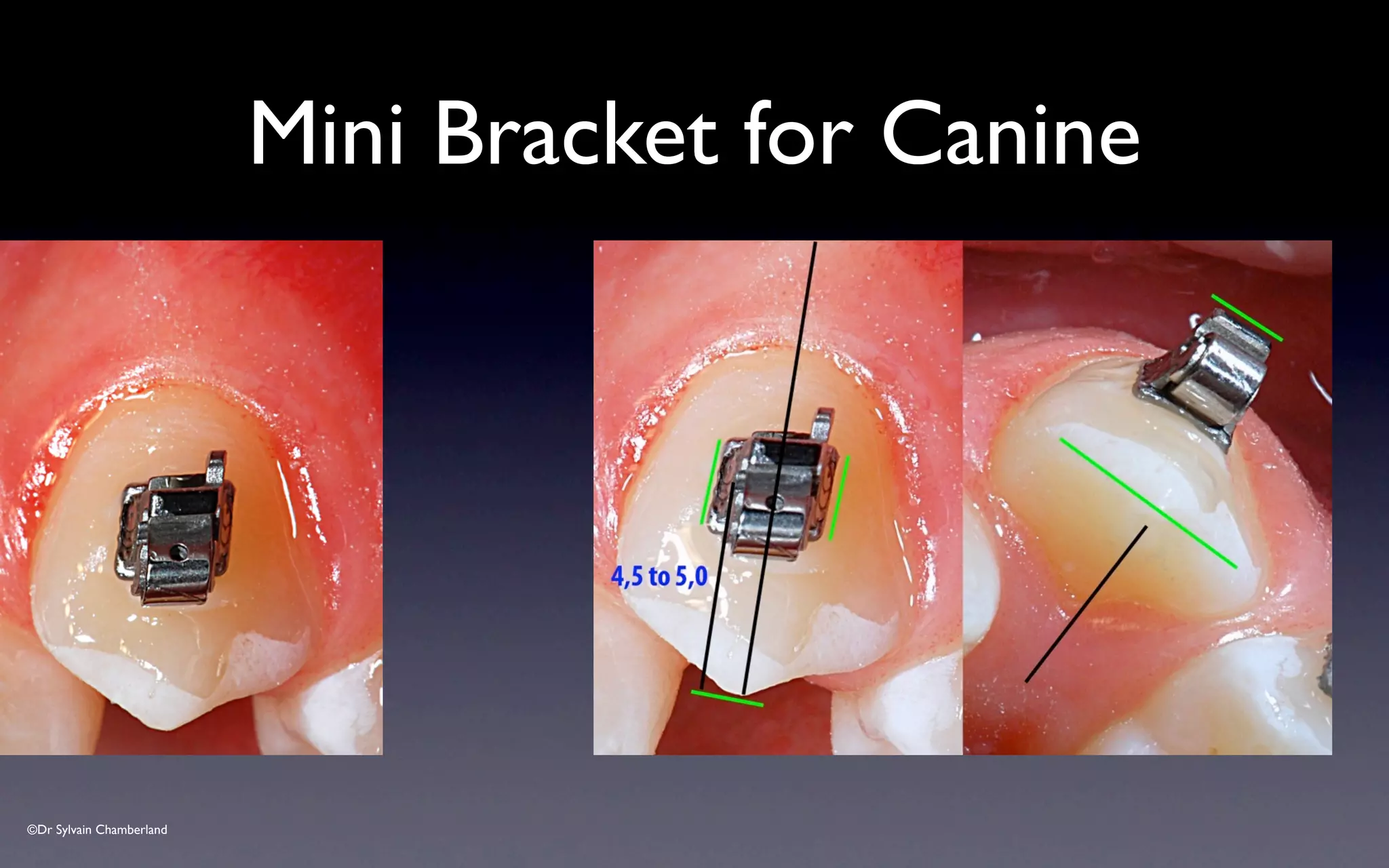
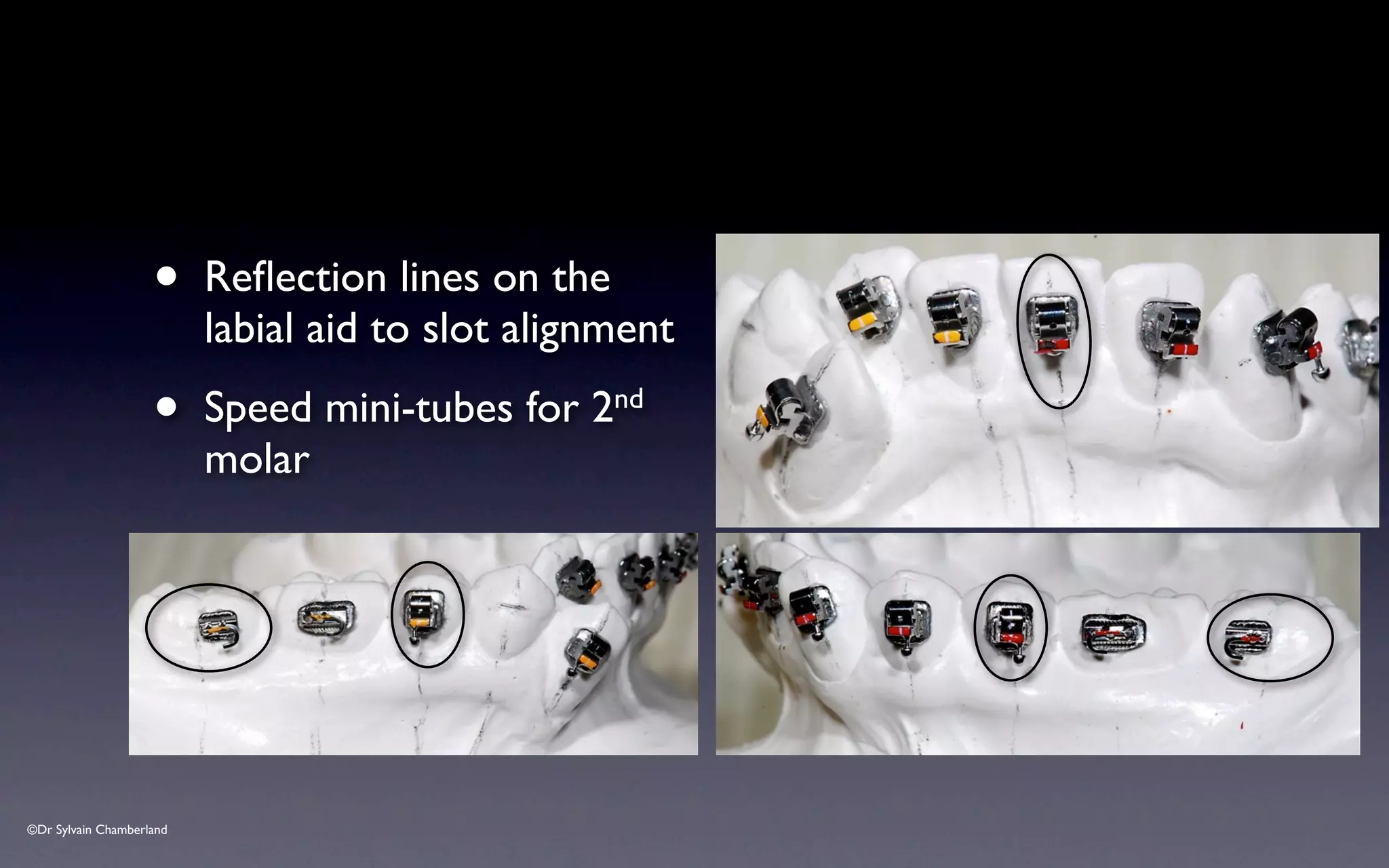
- The rounded portion of the spring clip should face occlusally in both arches.
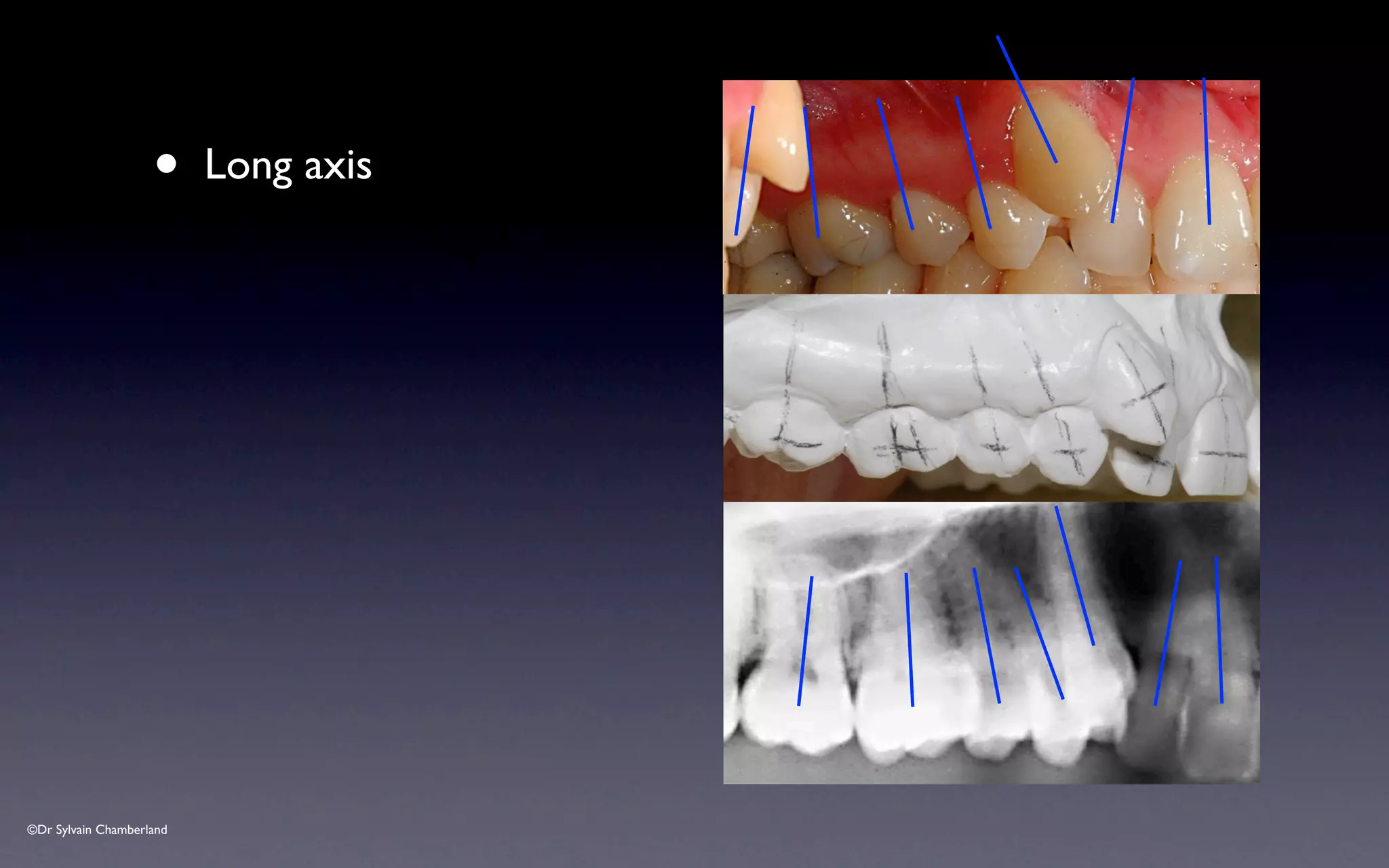
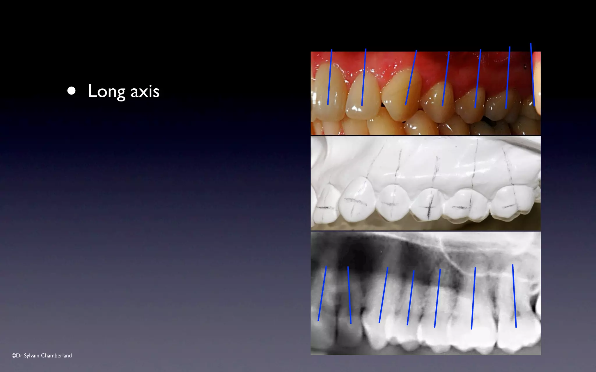
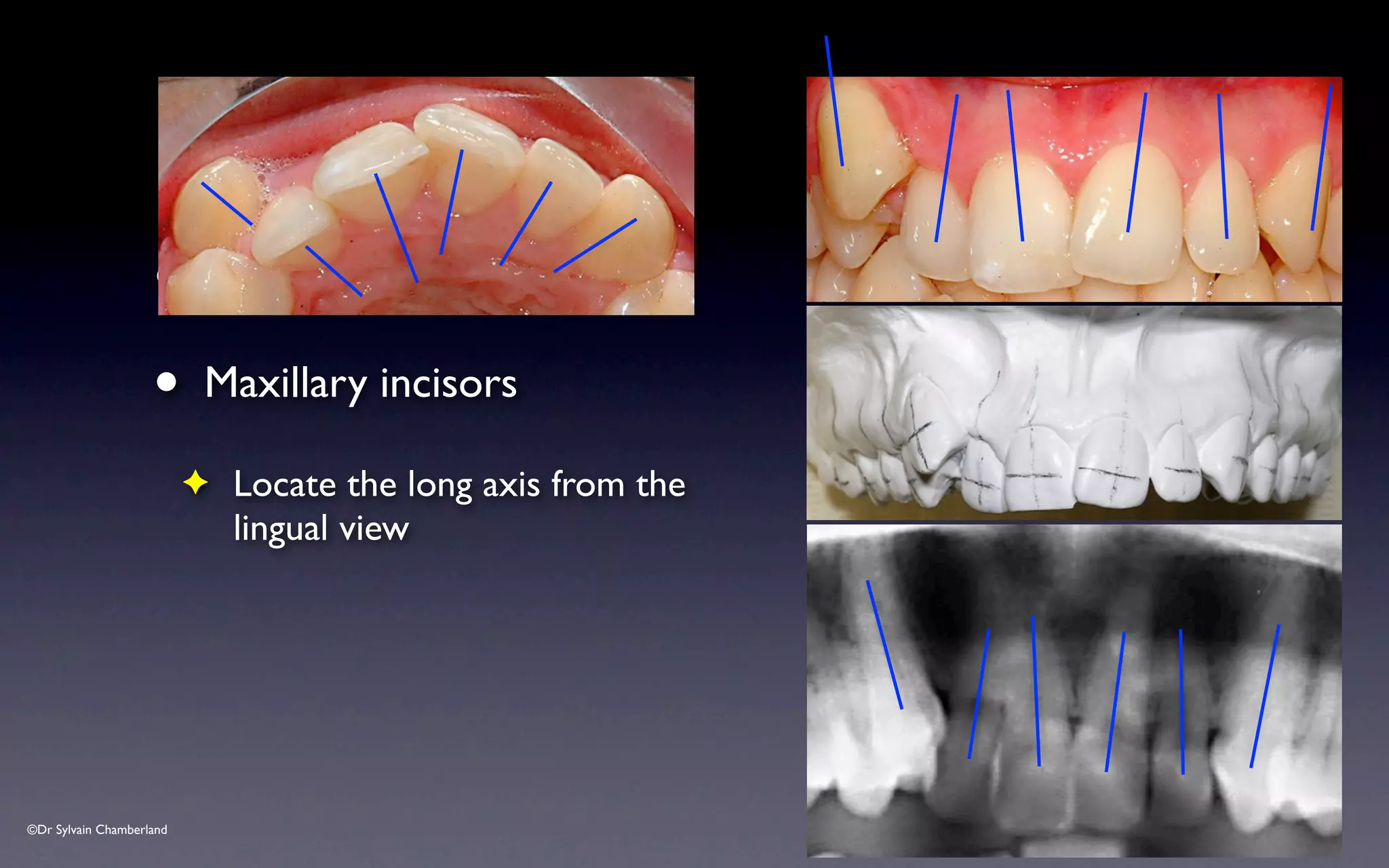
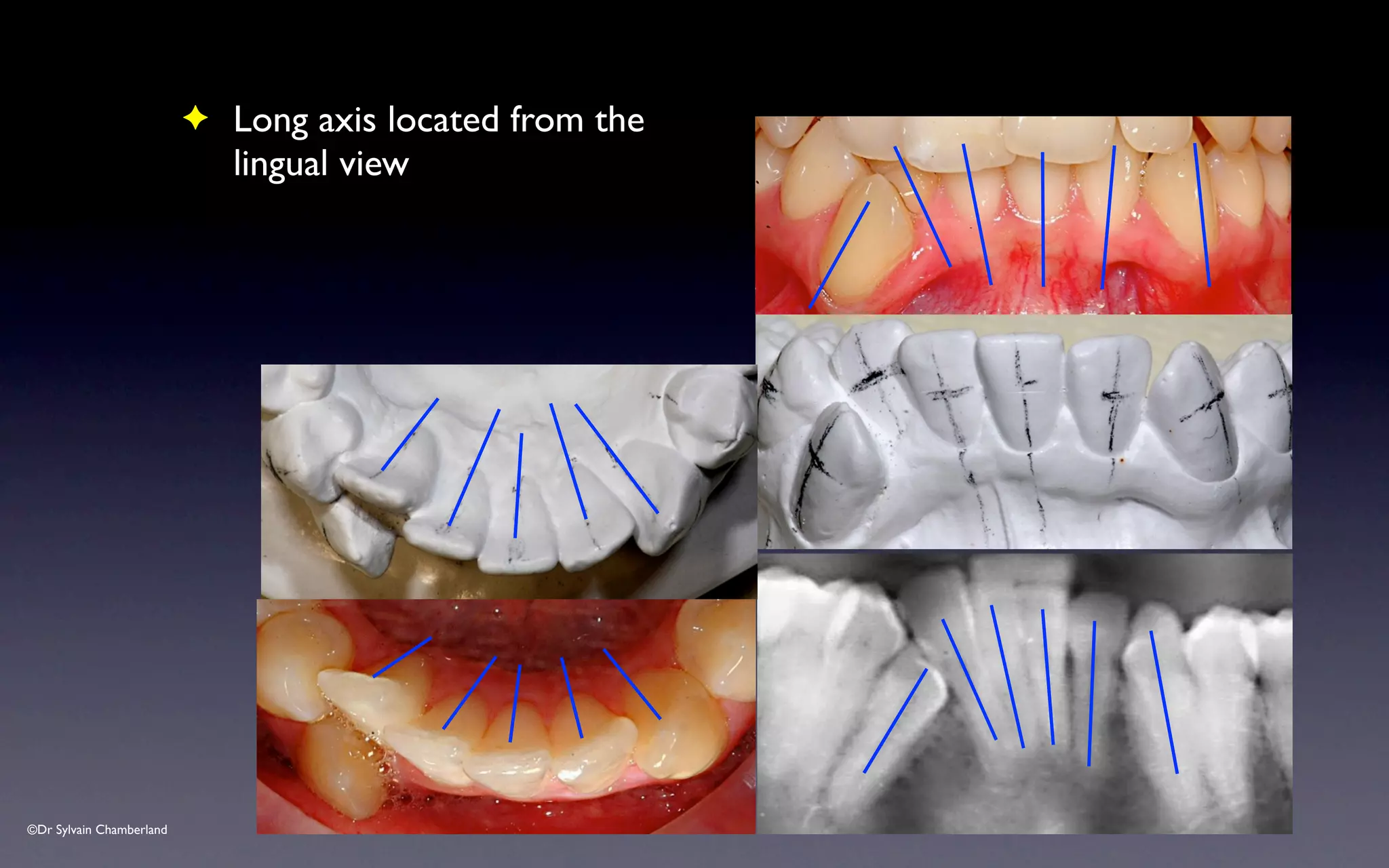
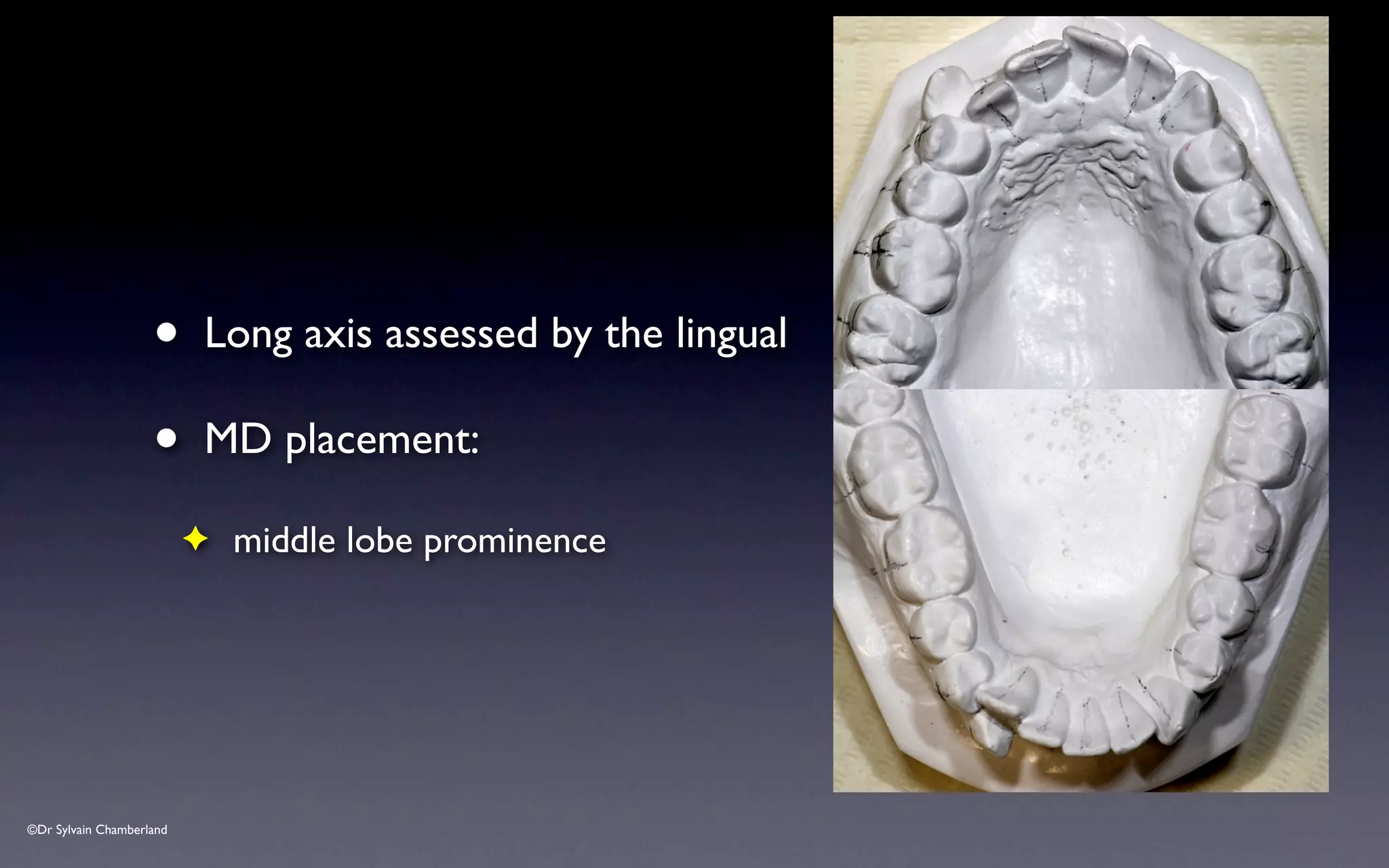
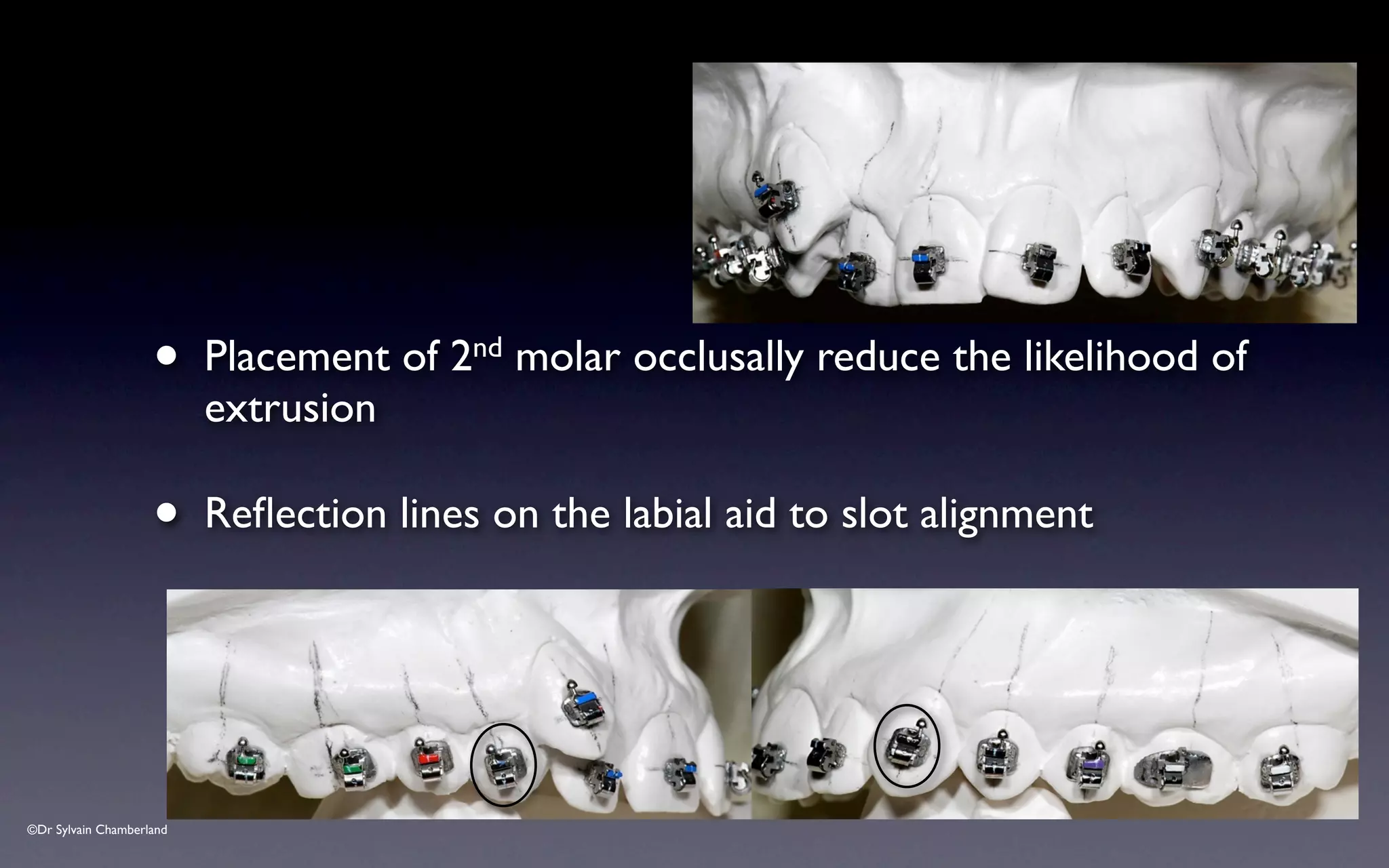
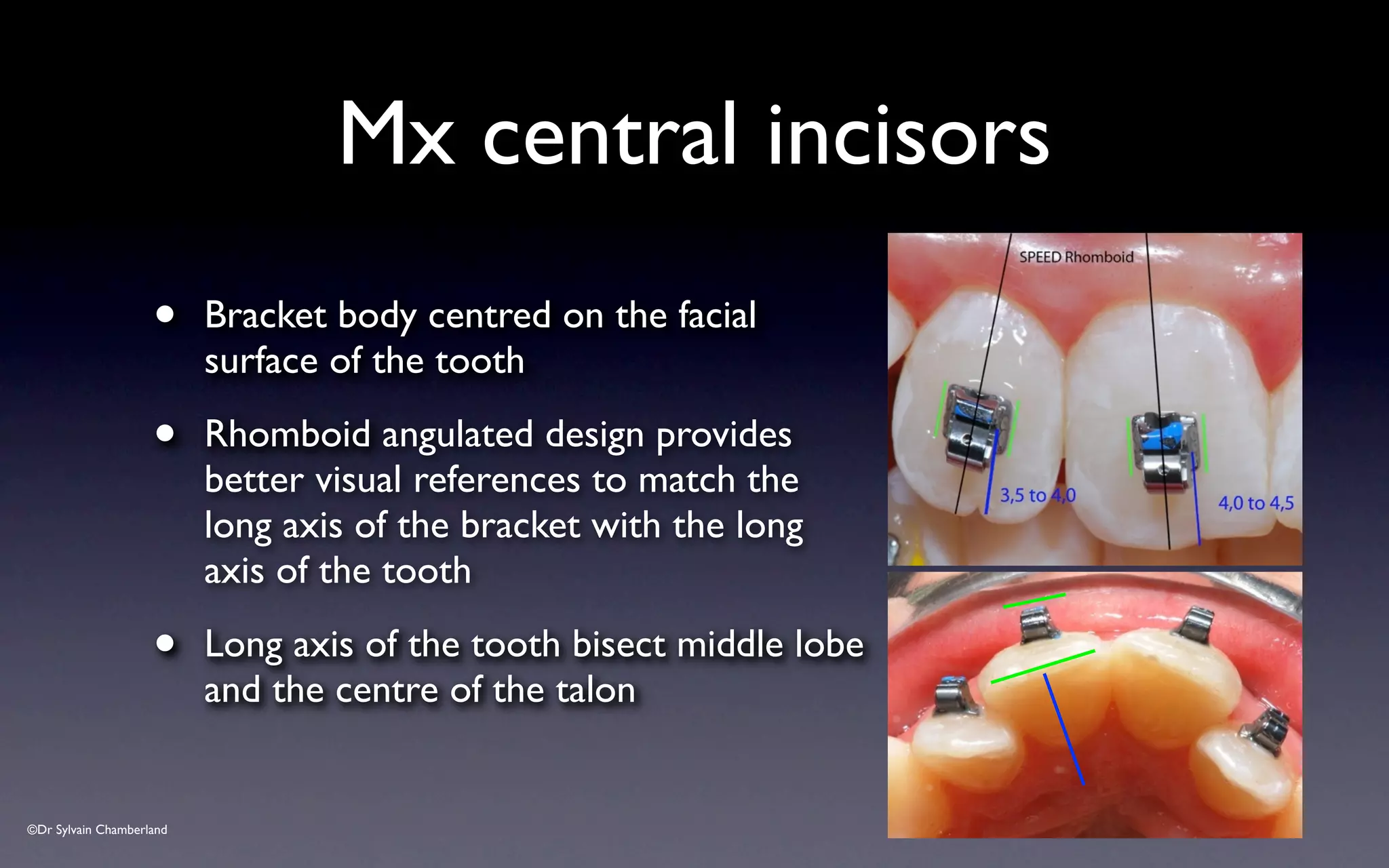
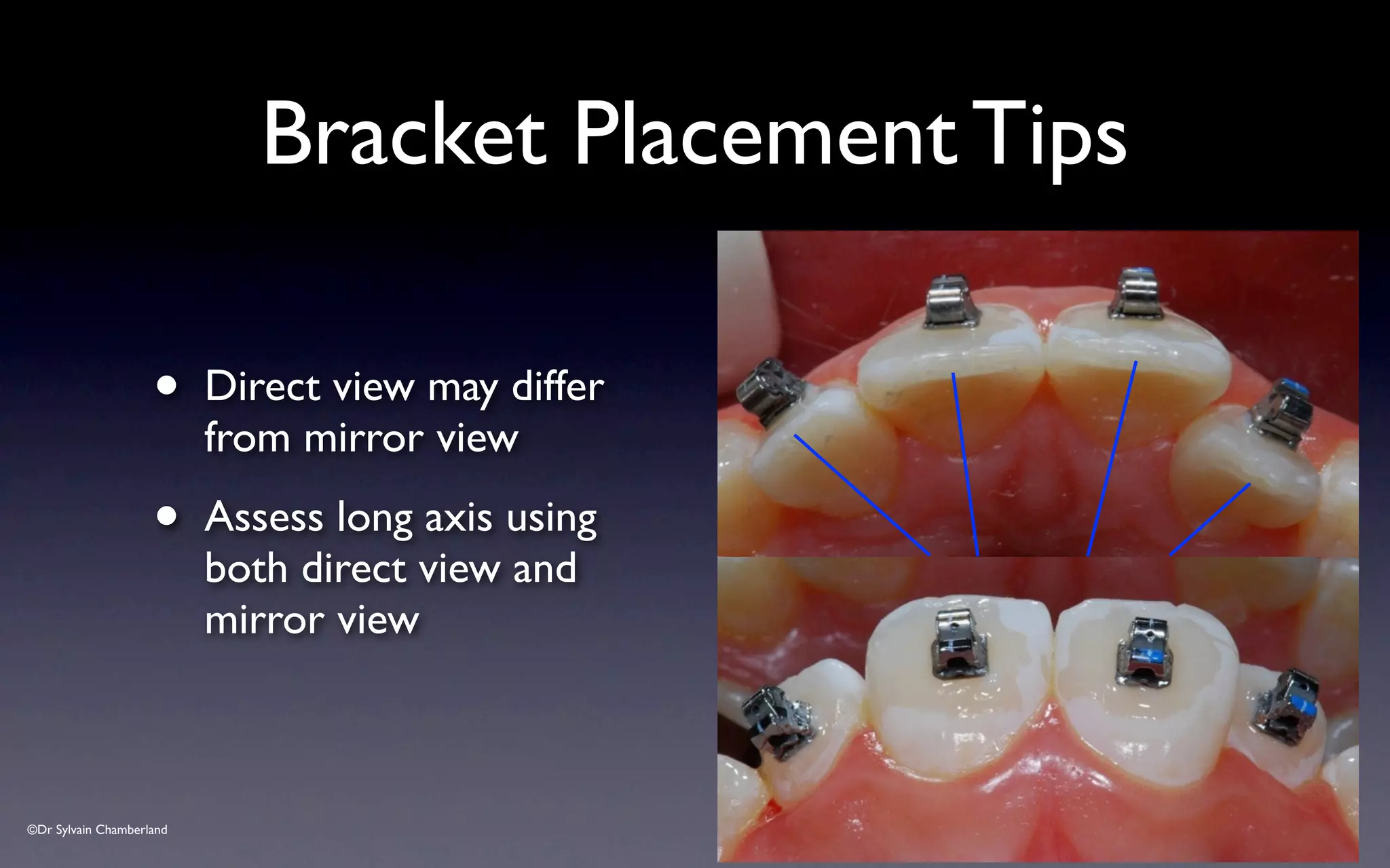
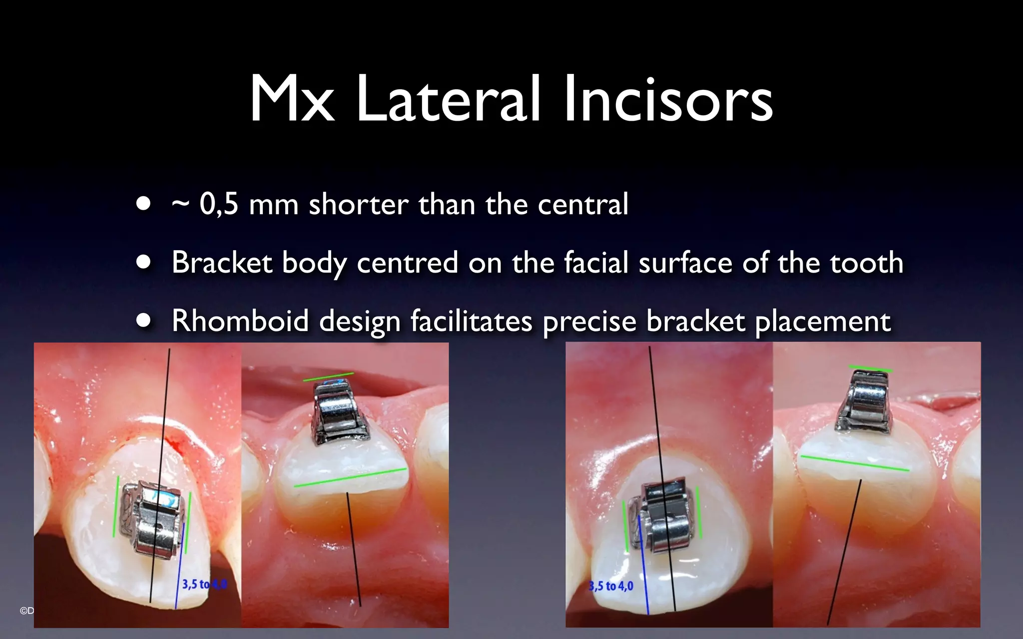
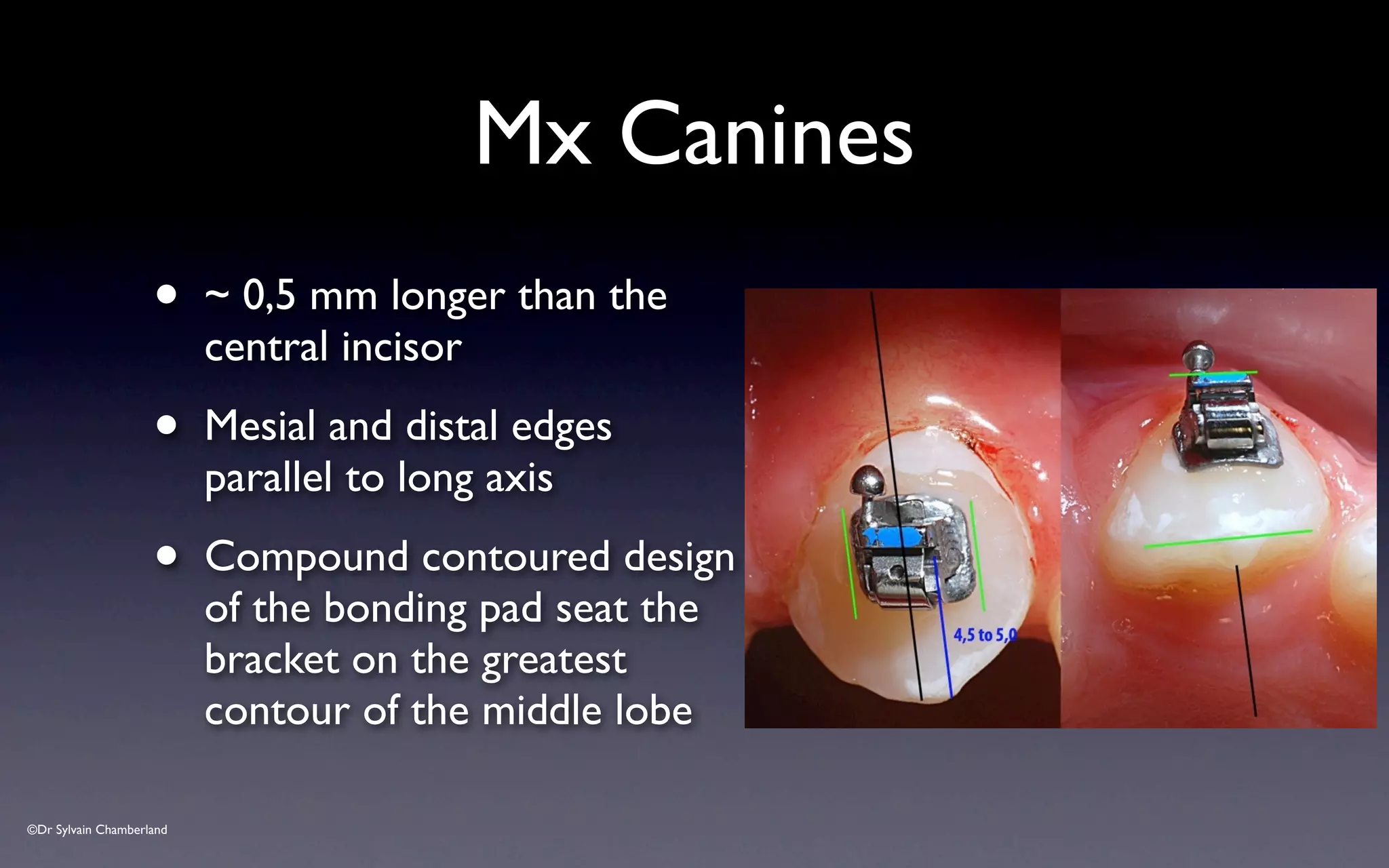
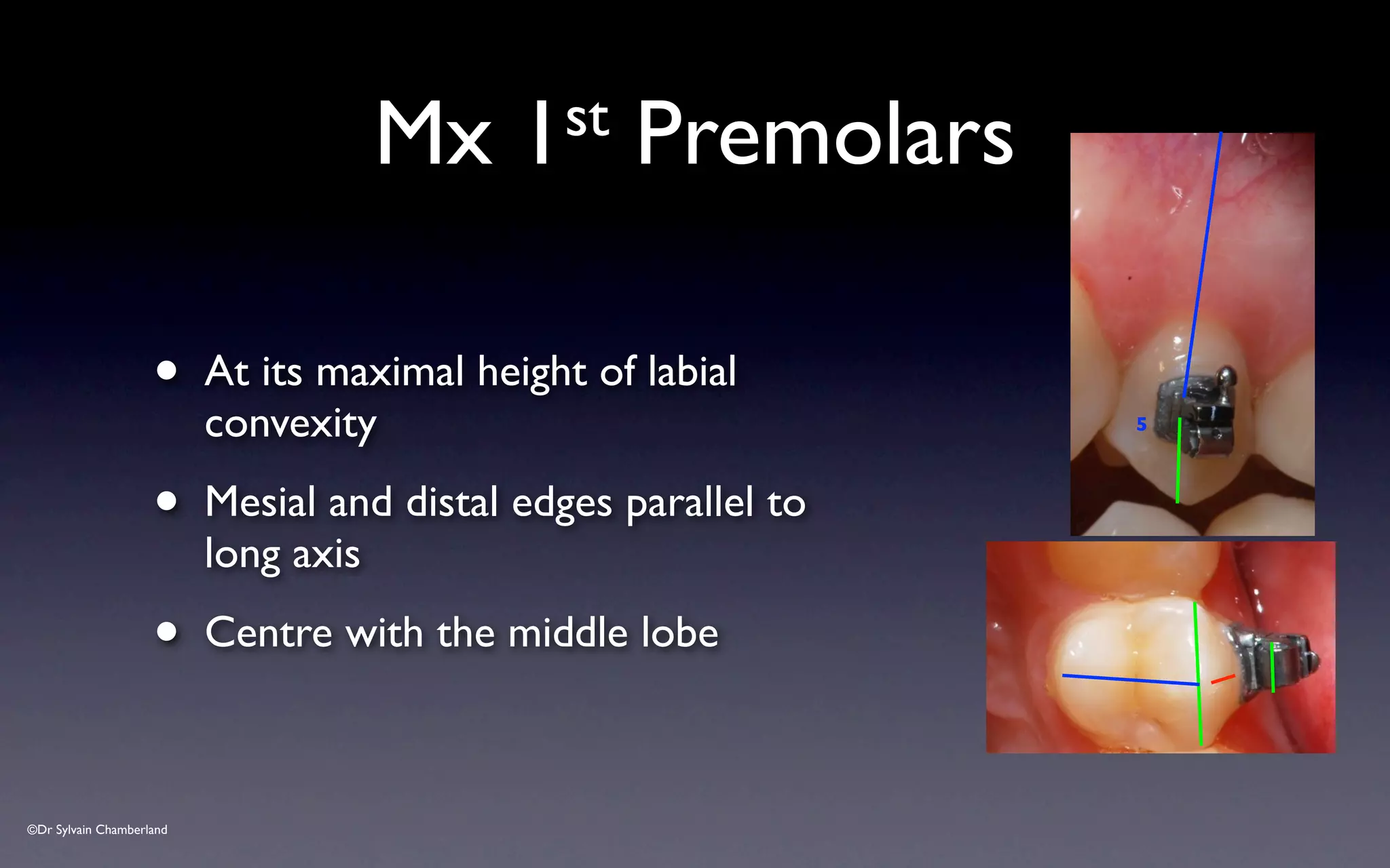
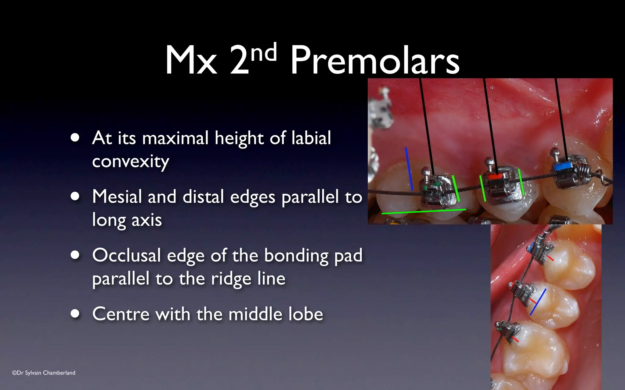
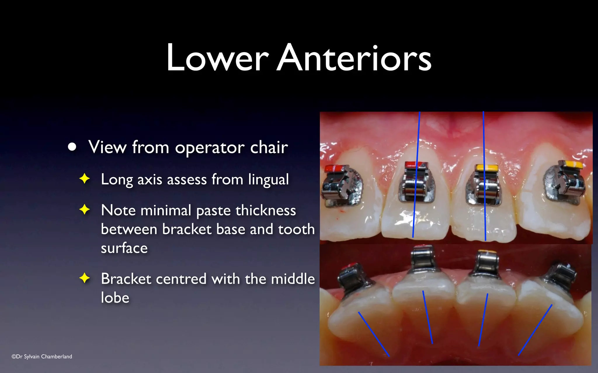
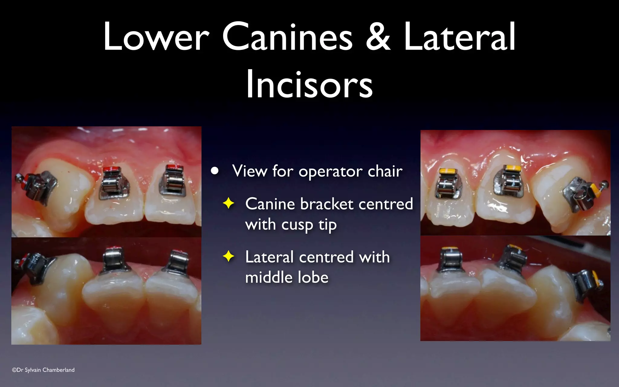
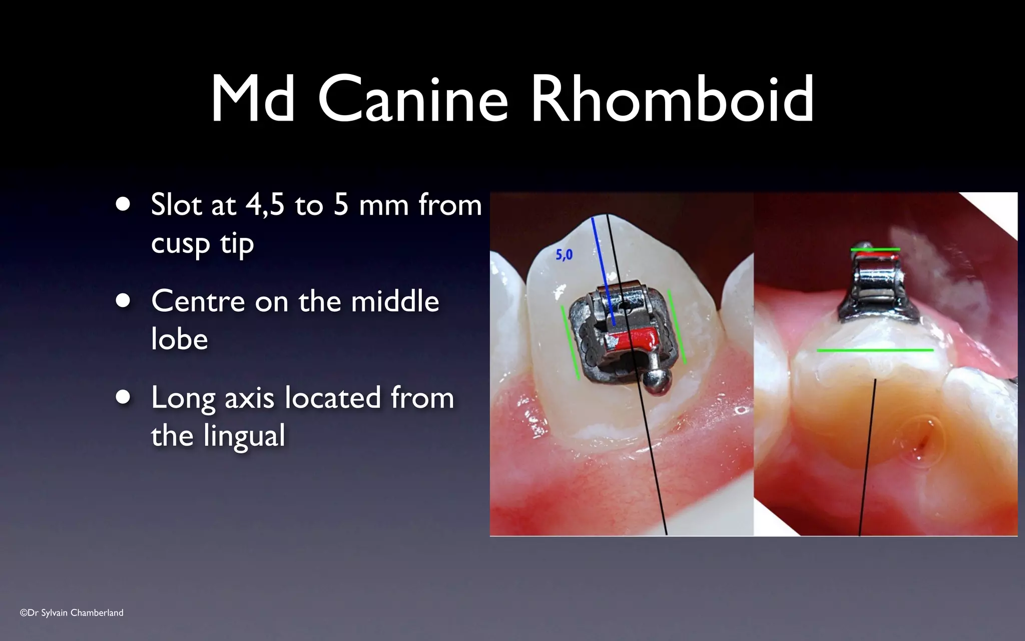
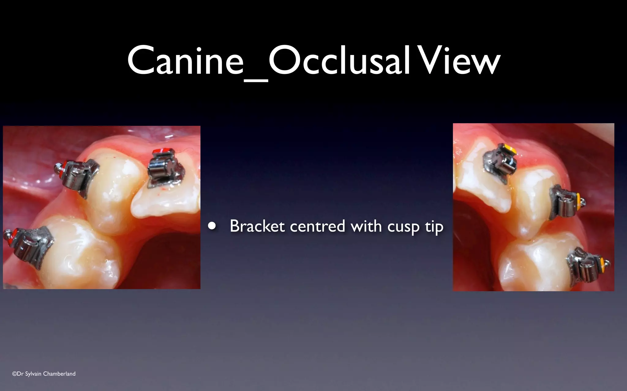
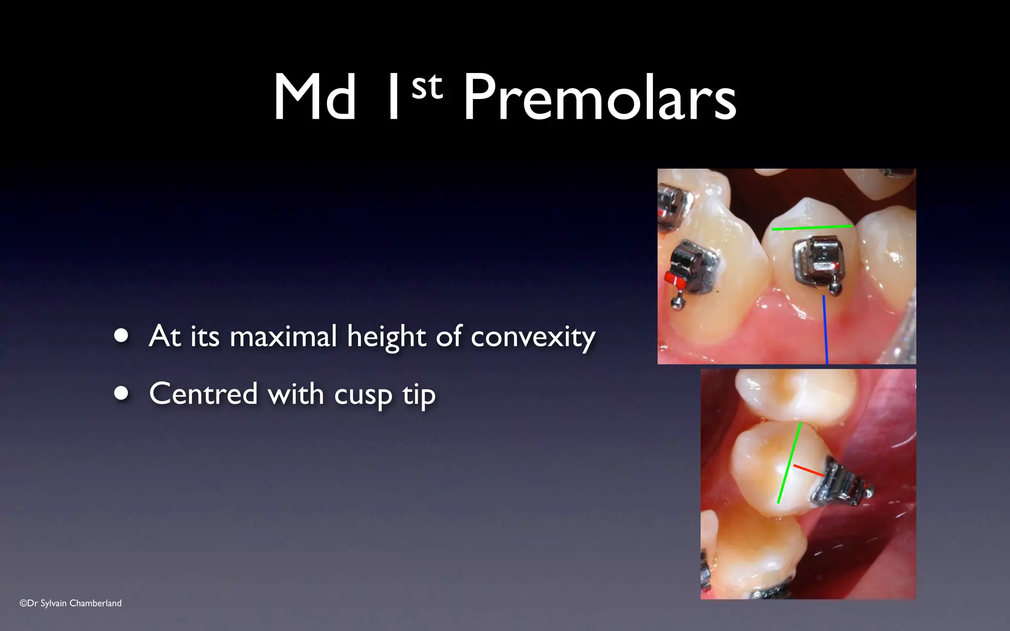
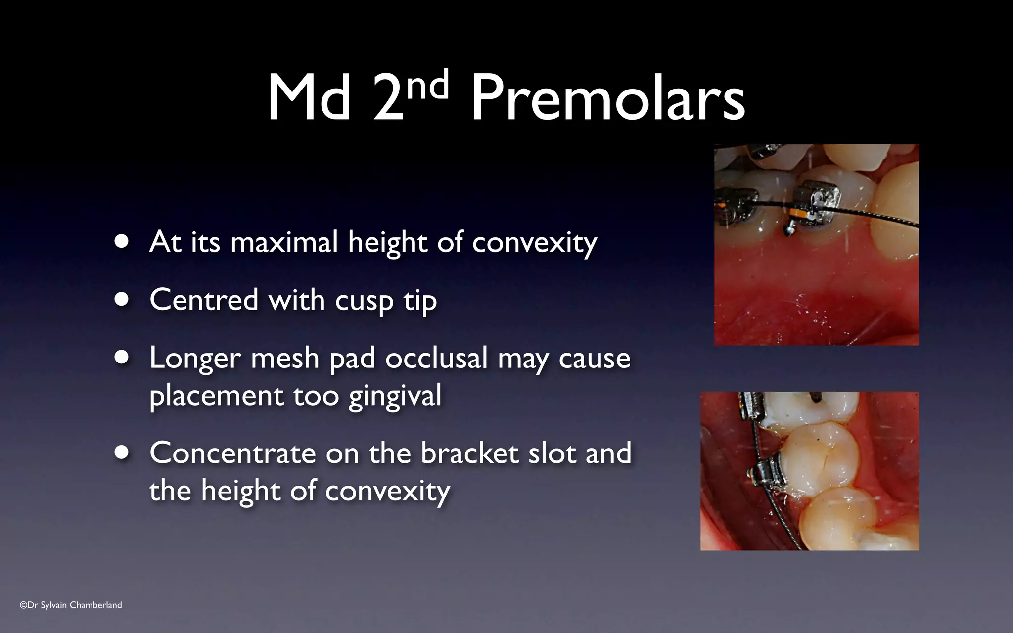
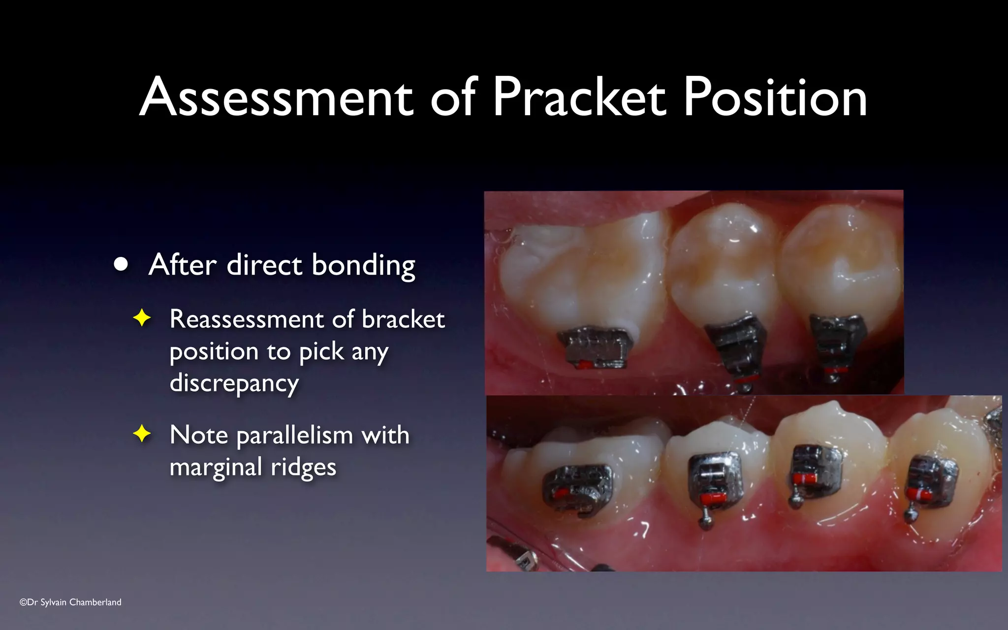
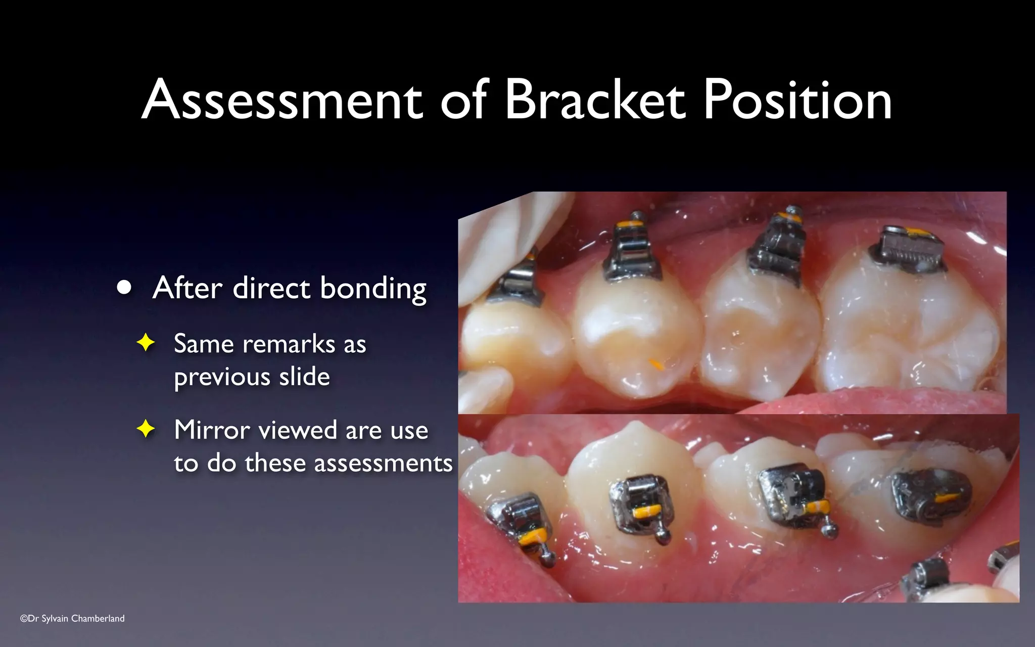
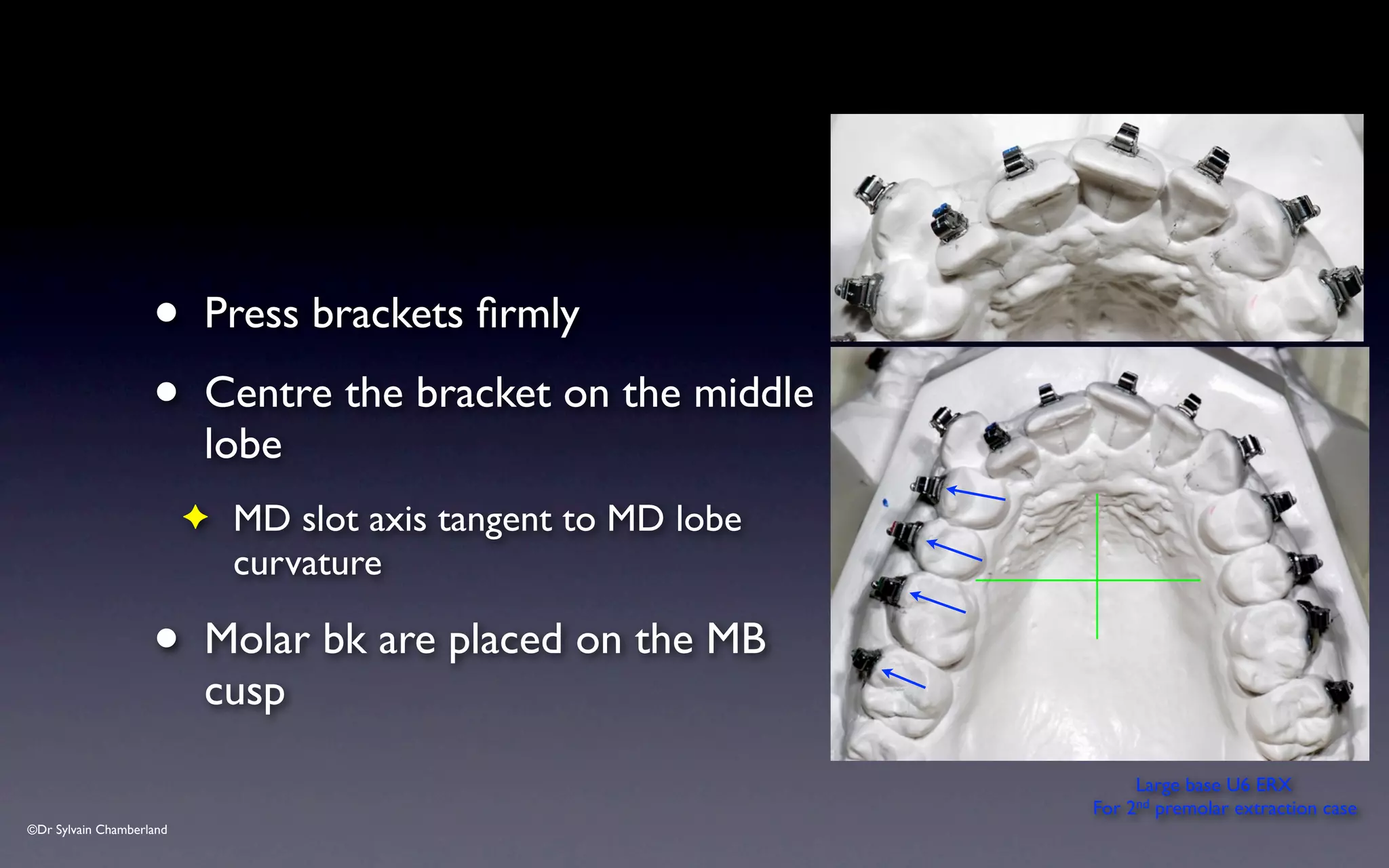
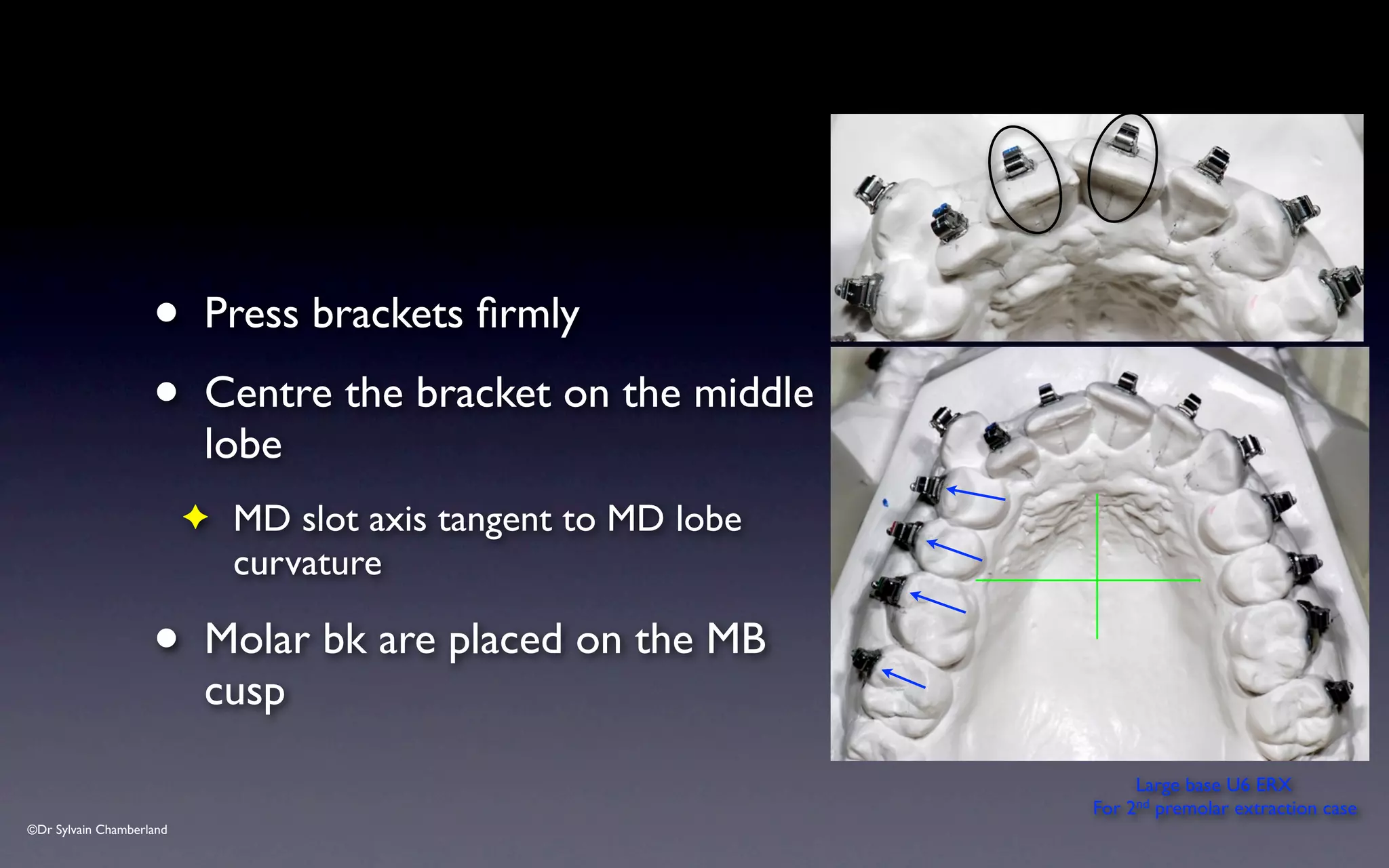
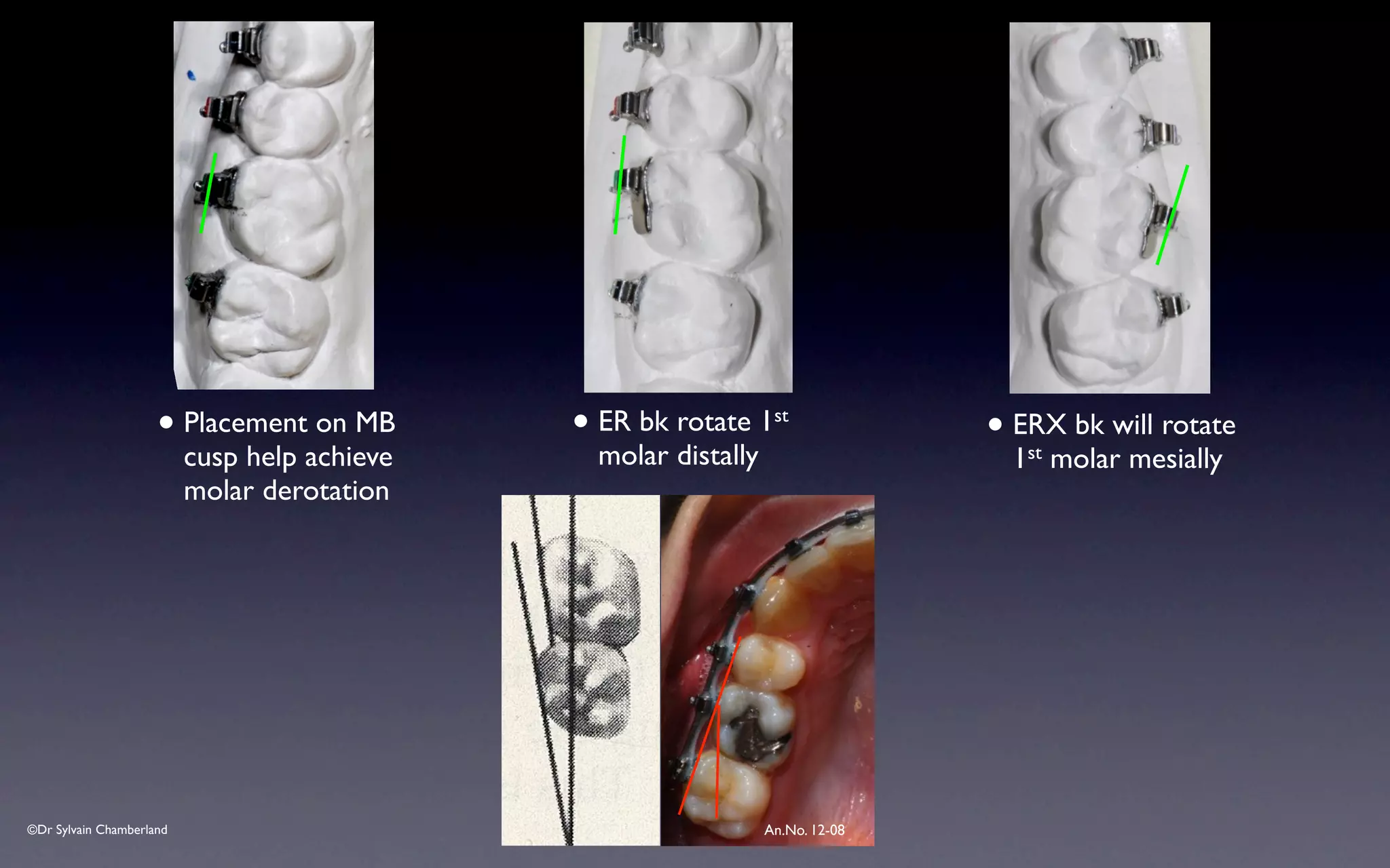
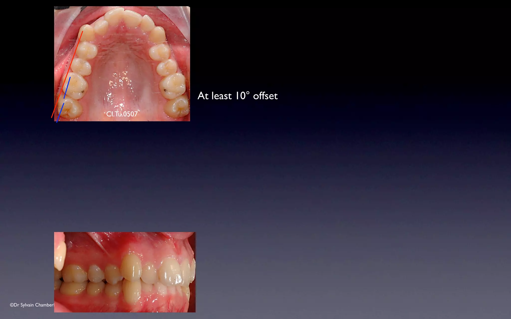
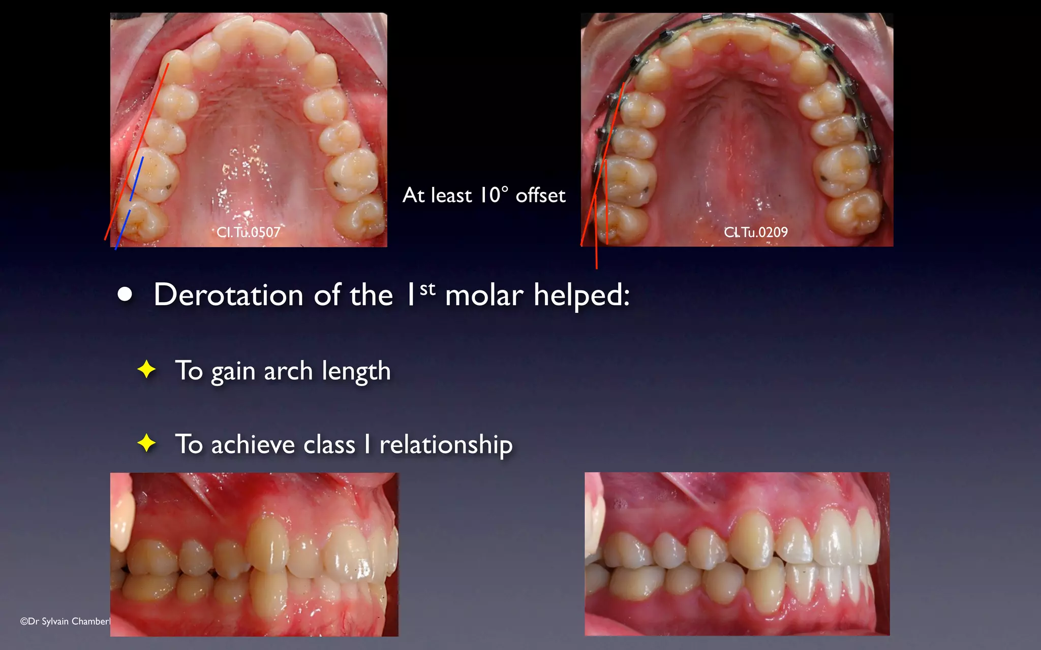
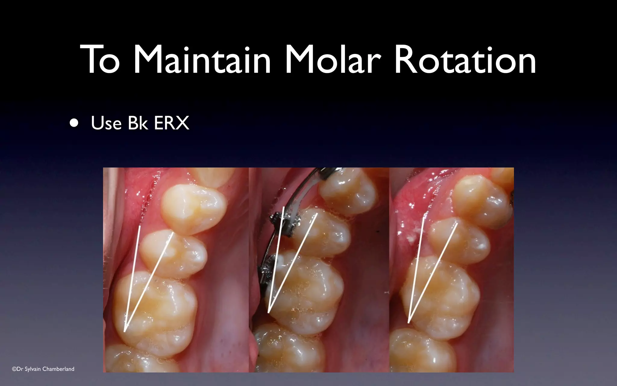
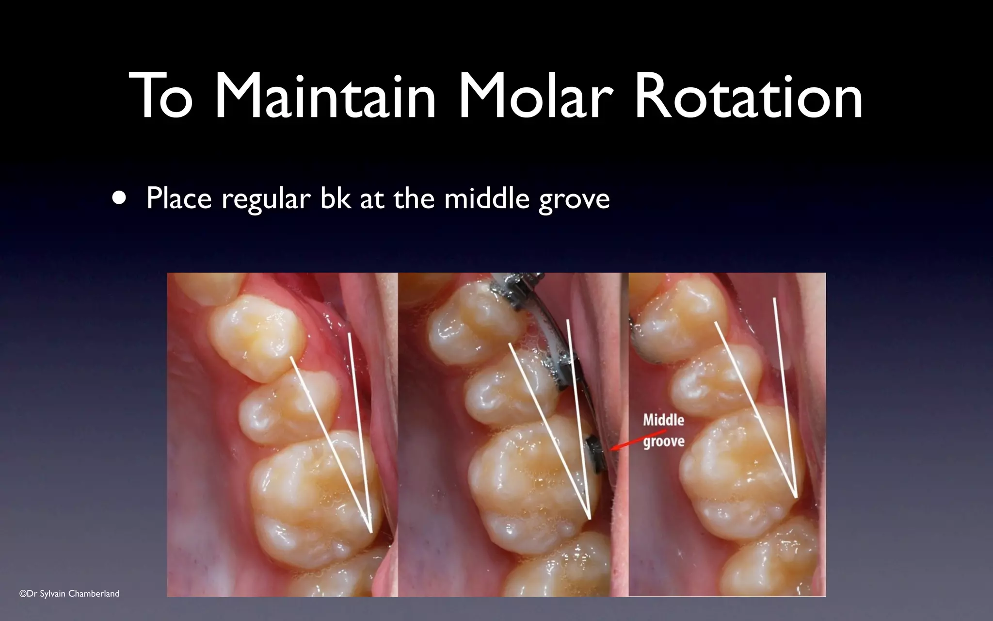
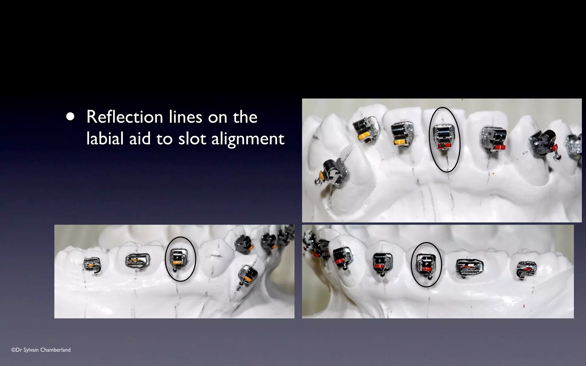
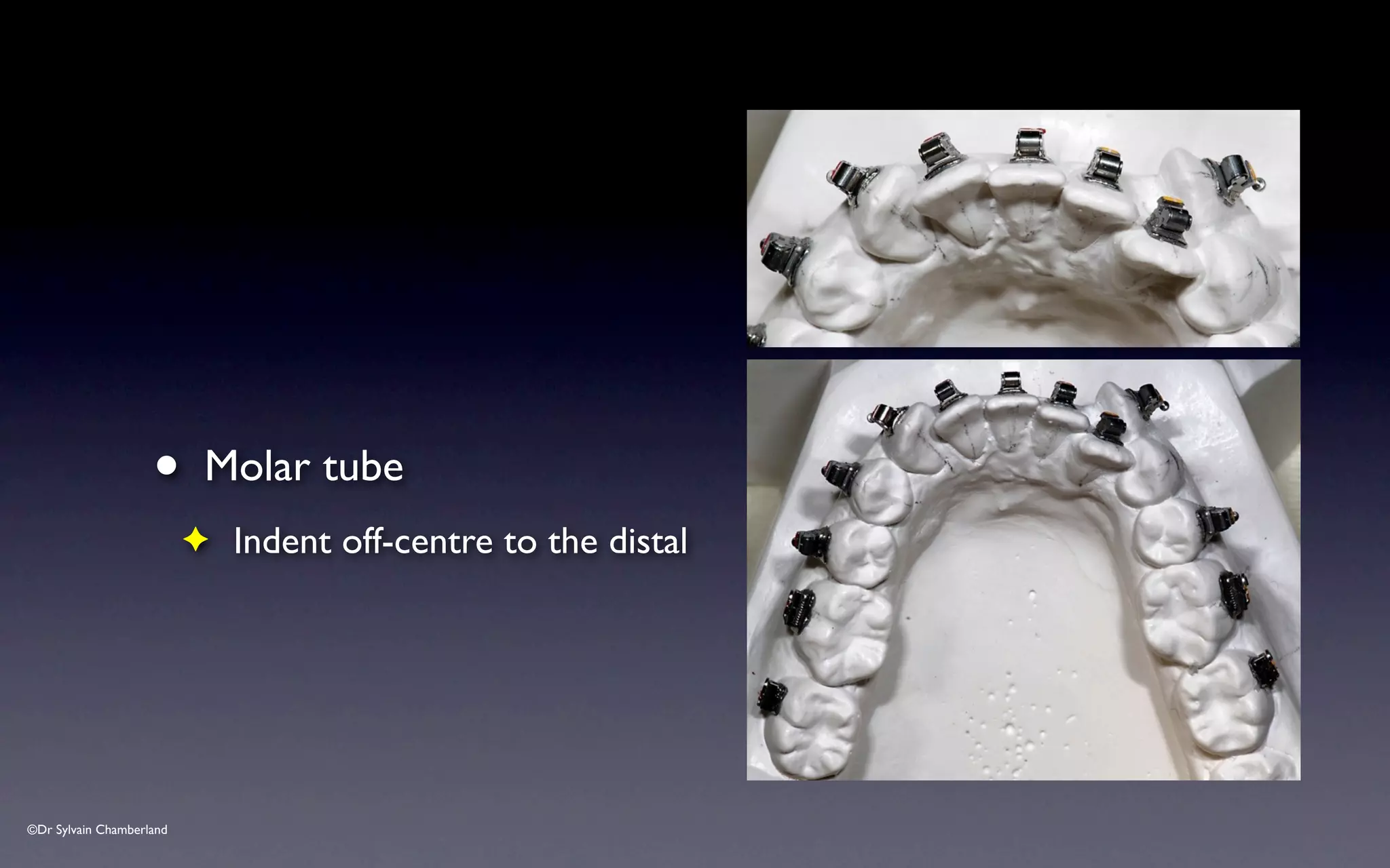
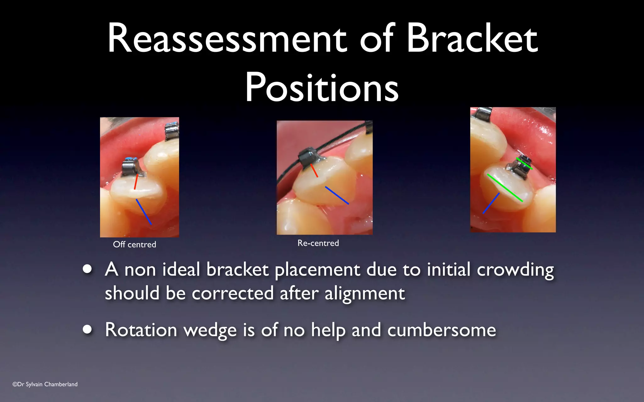
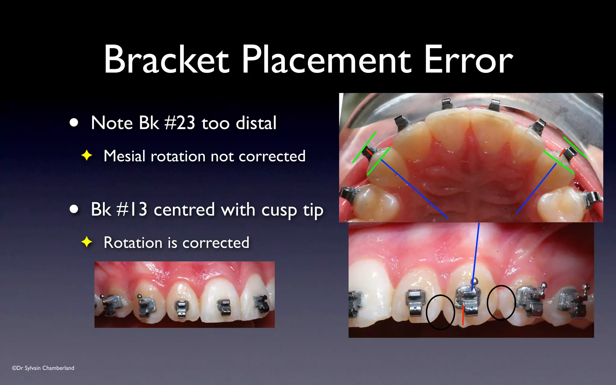
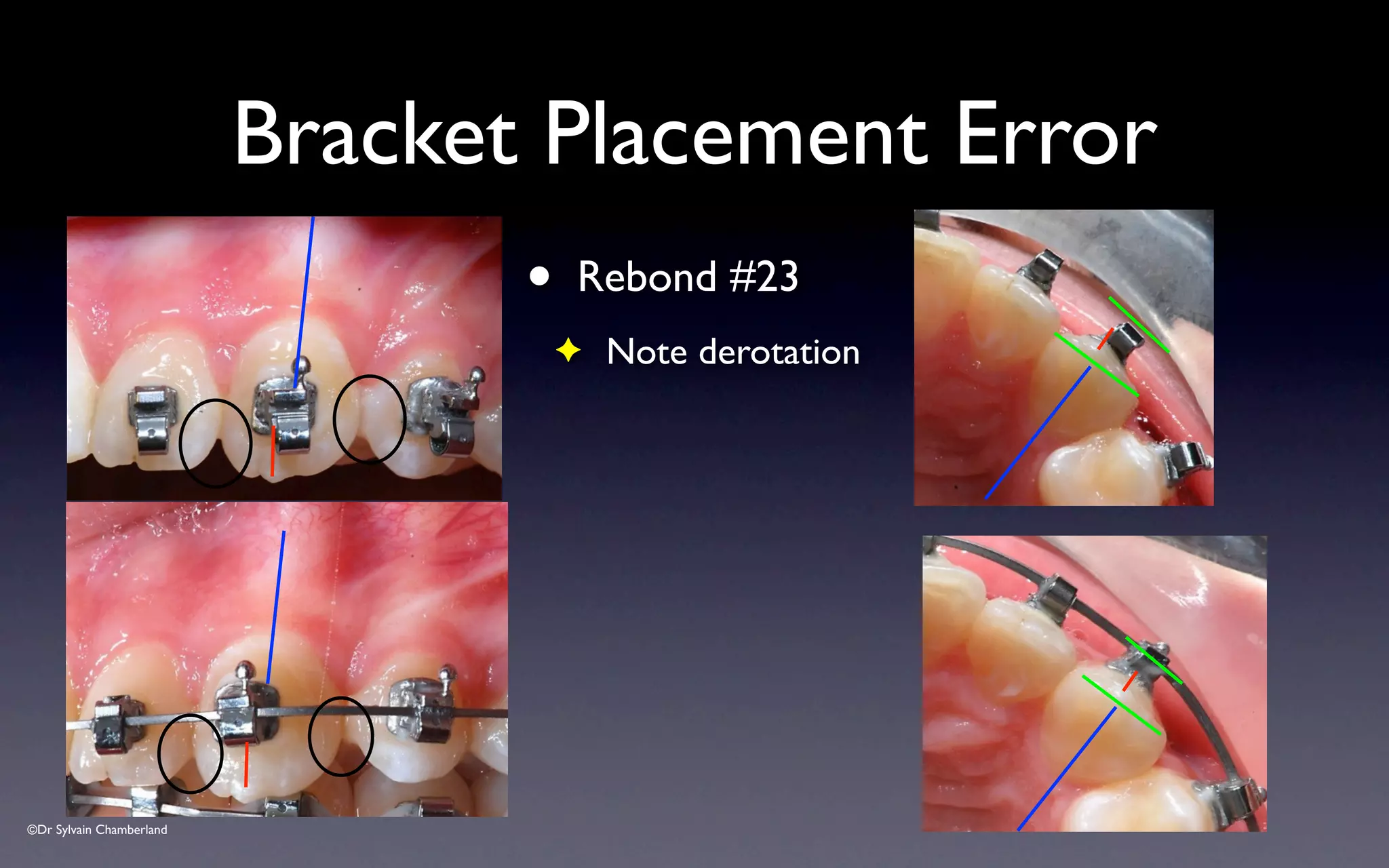
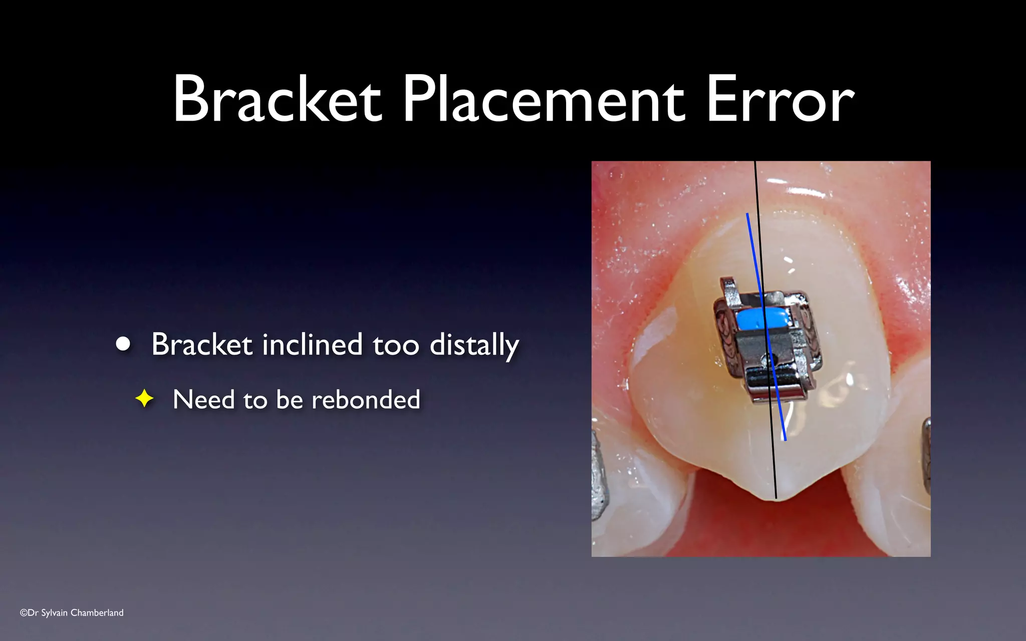
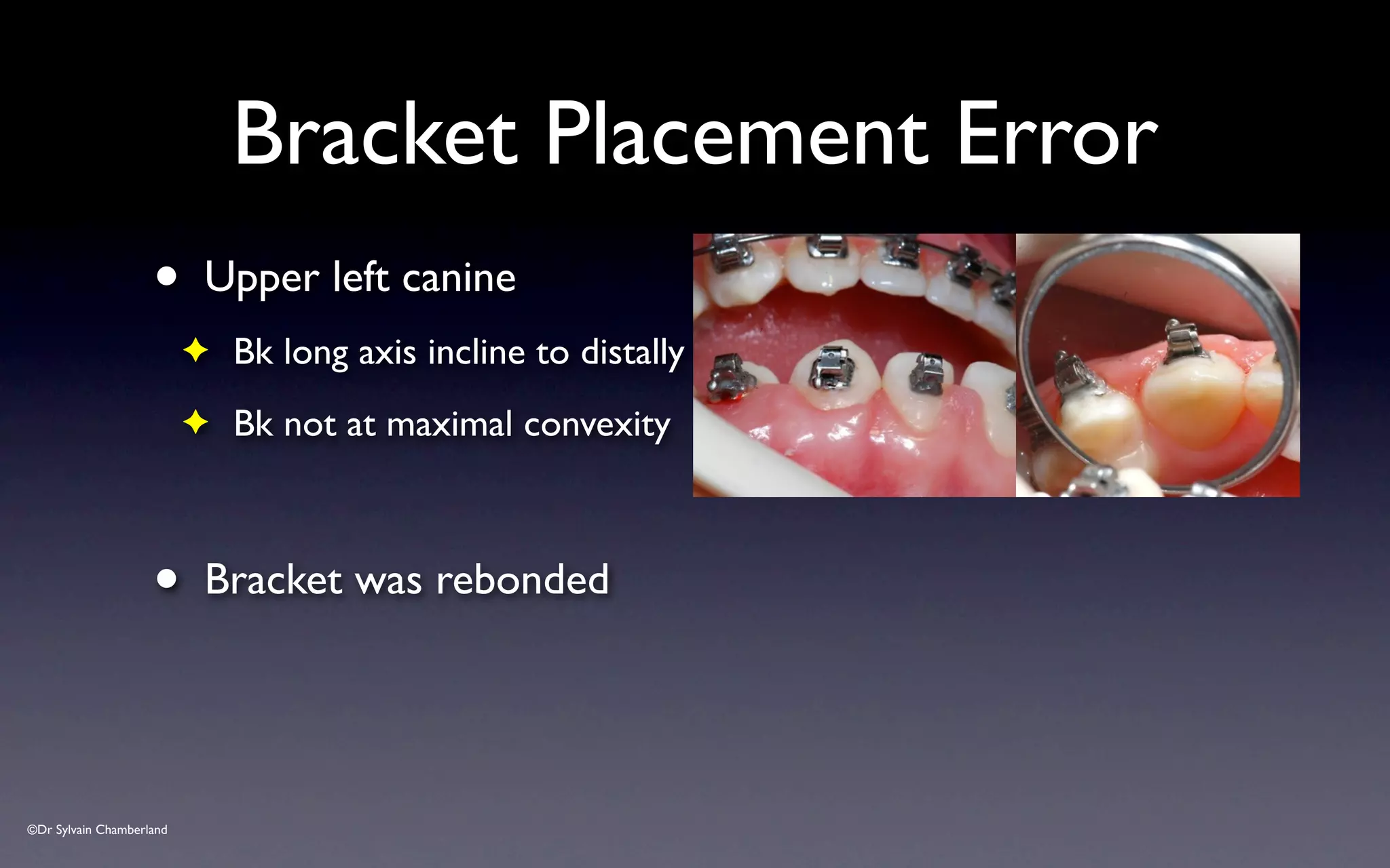
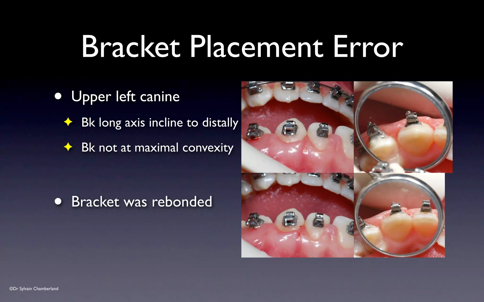
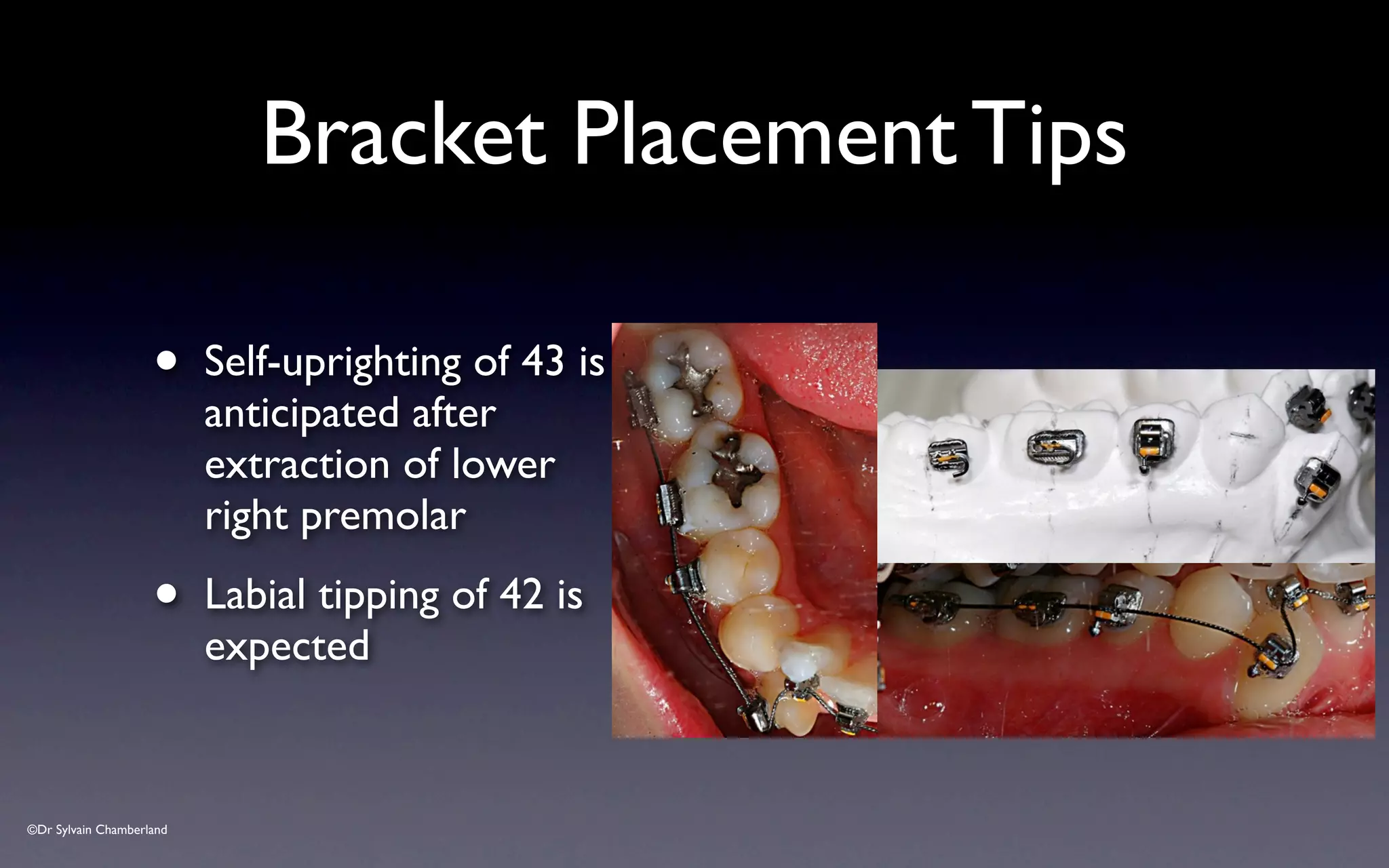
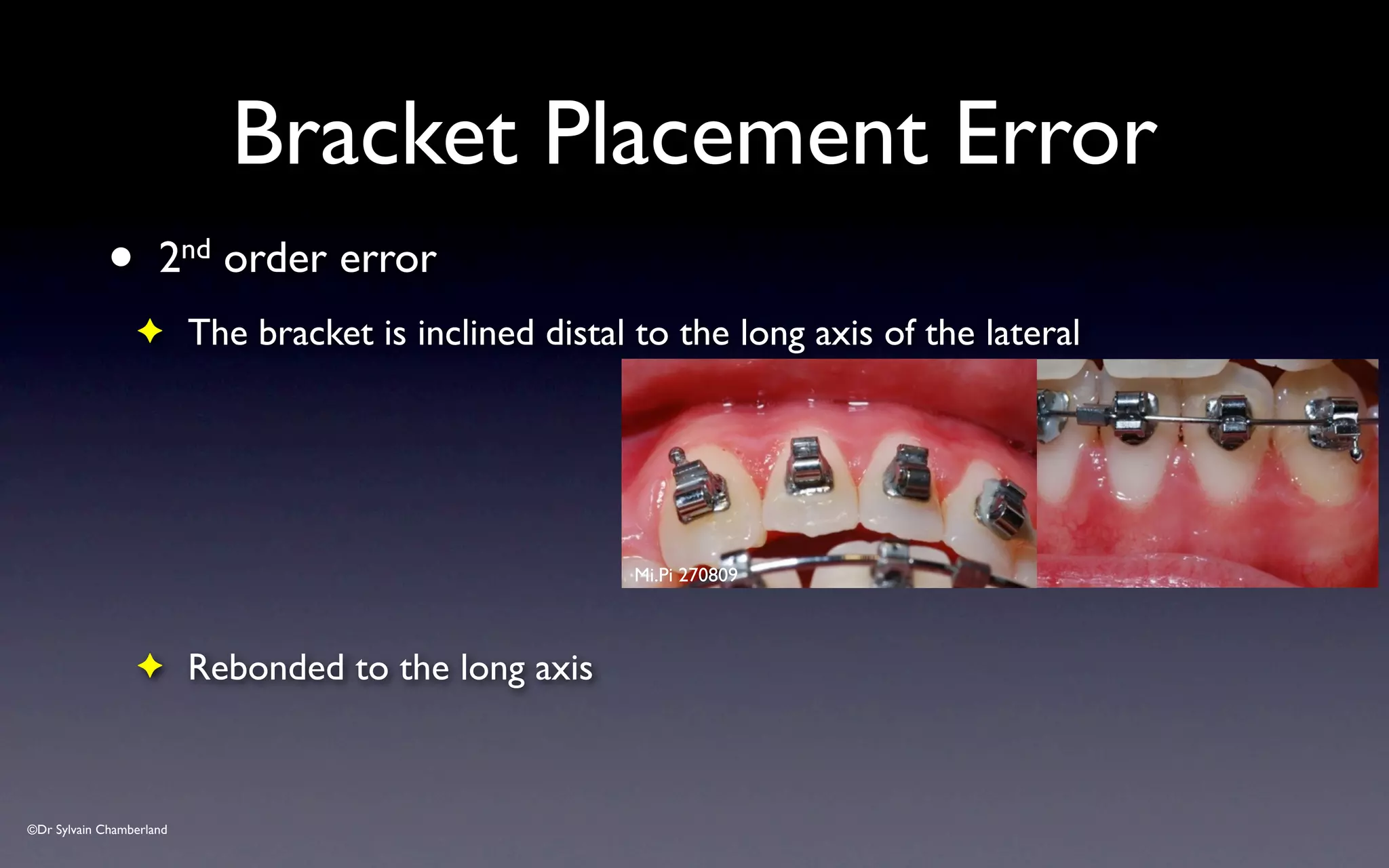
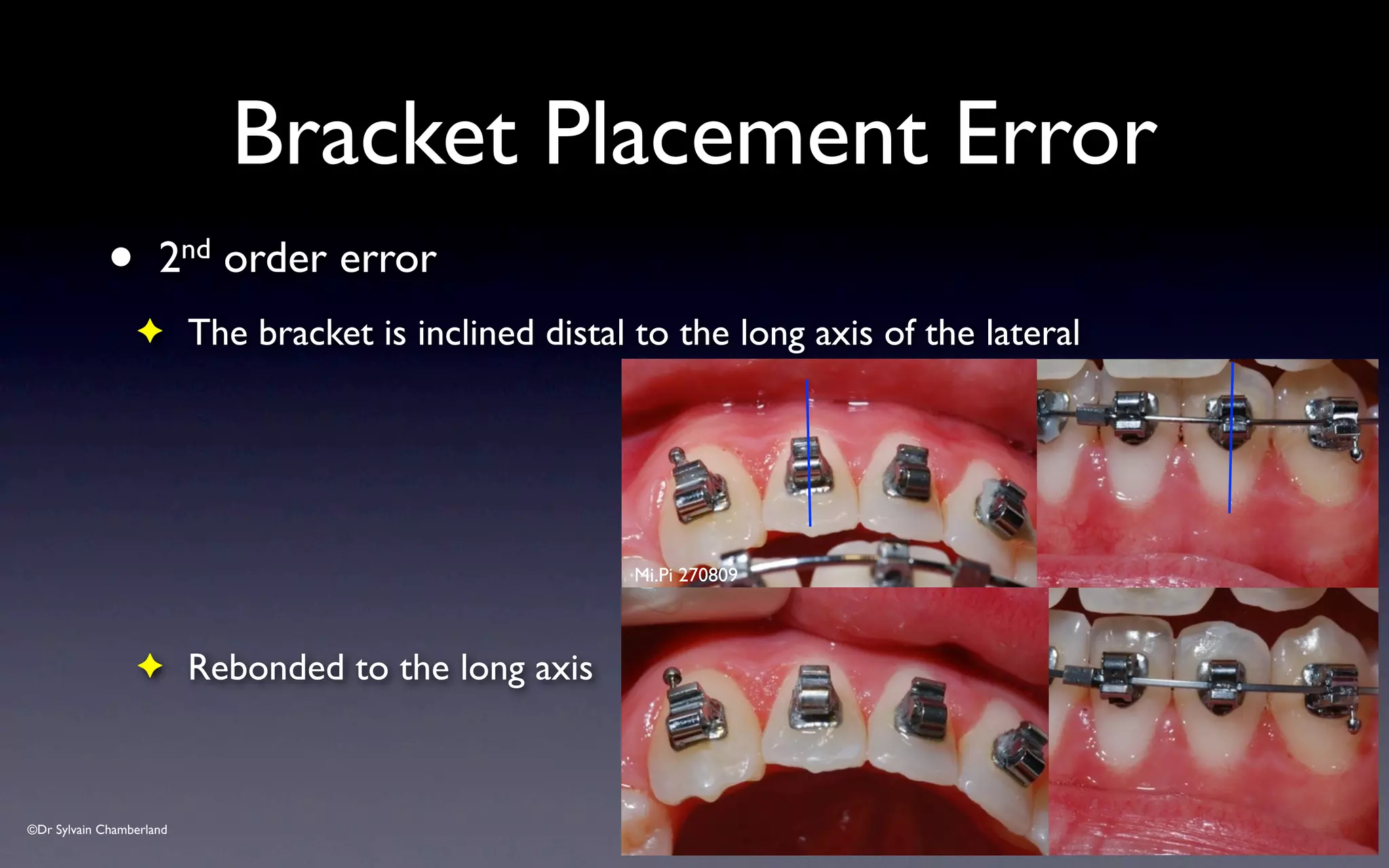
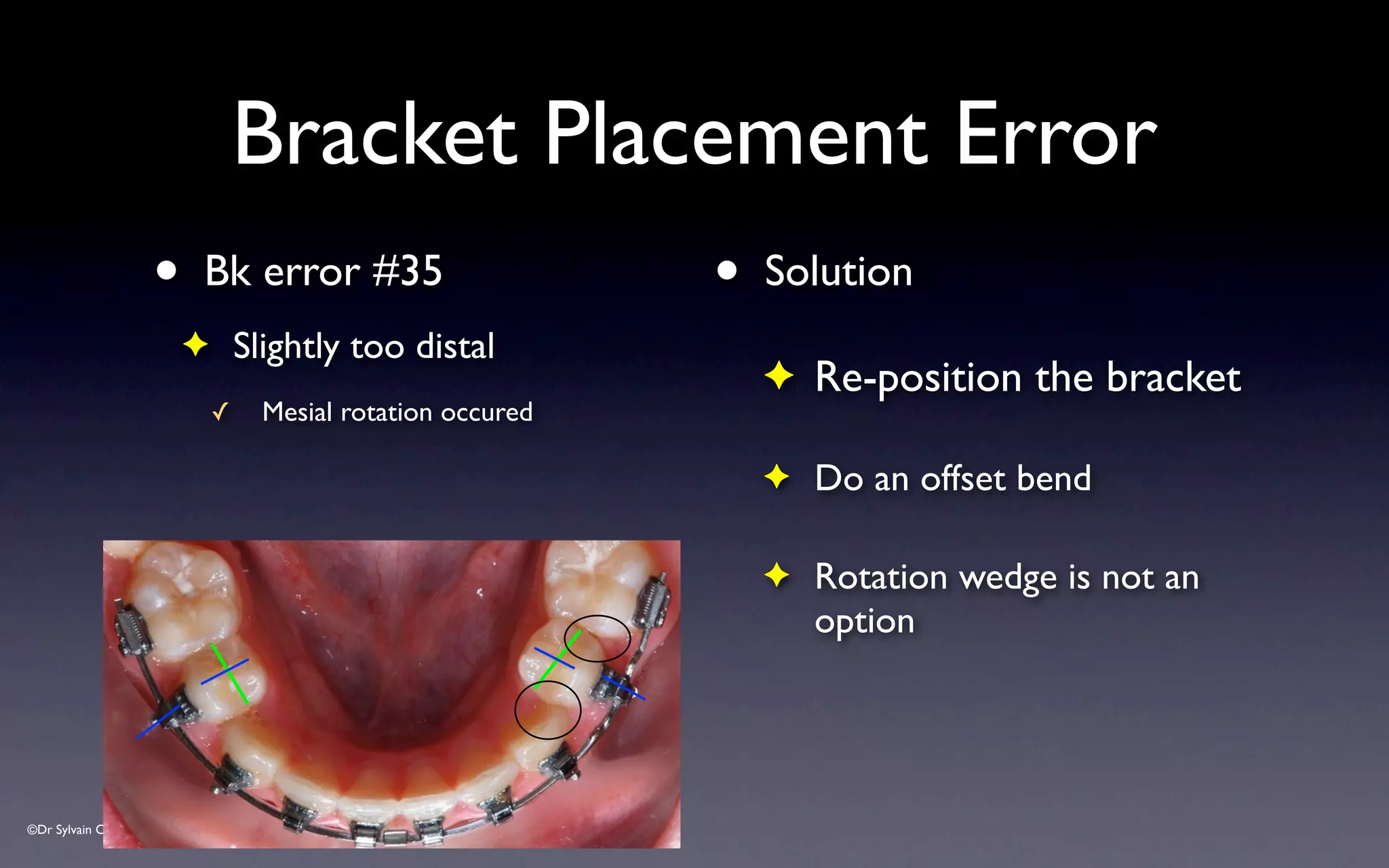
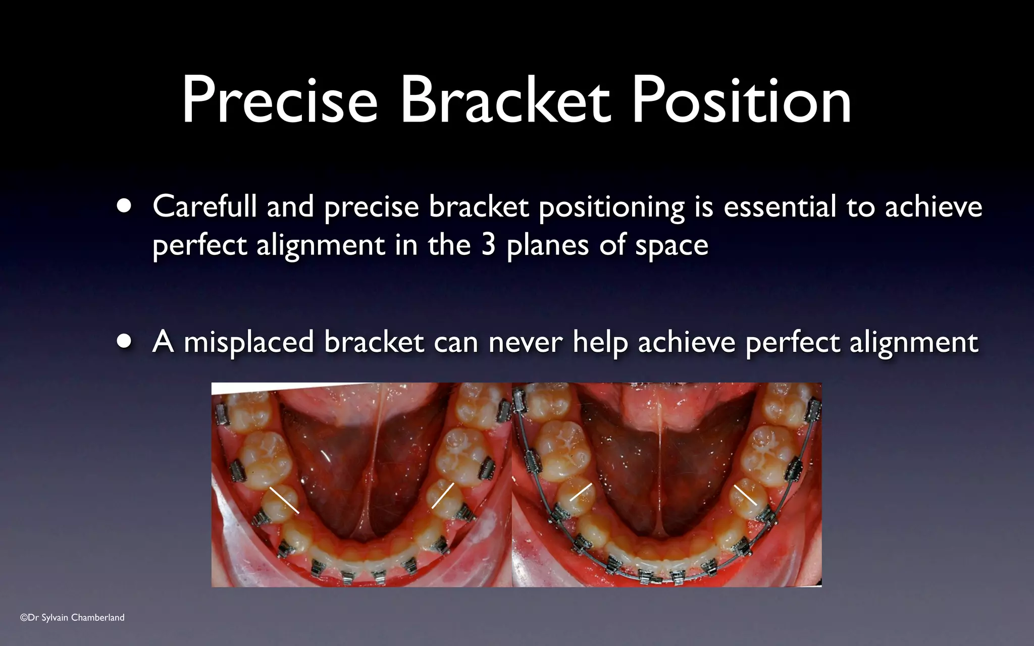
- Bracket placement should have the mesial and distal edges parallel to the long axis of each tooth.
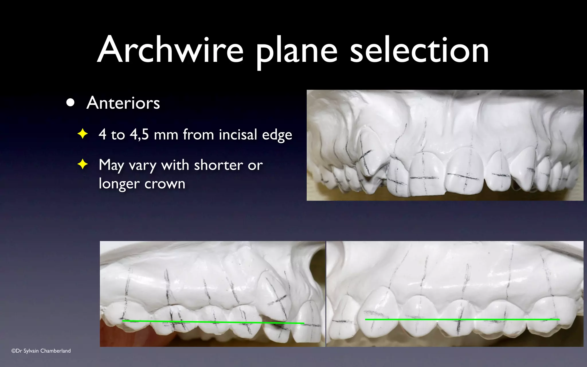
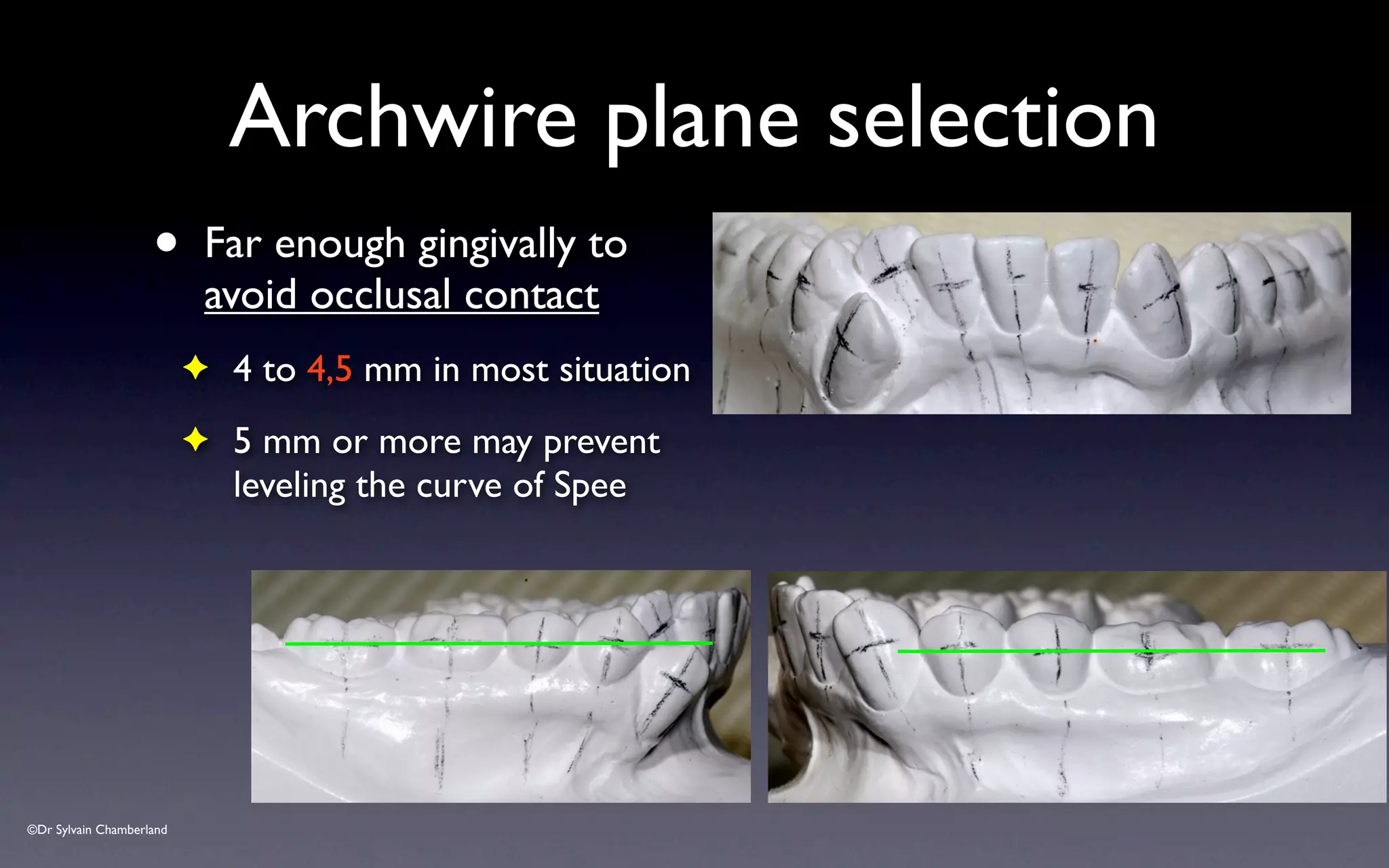
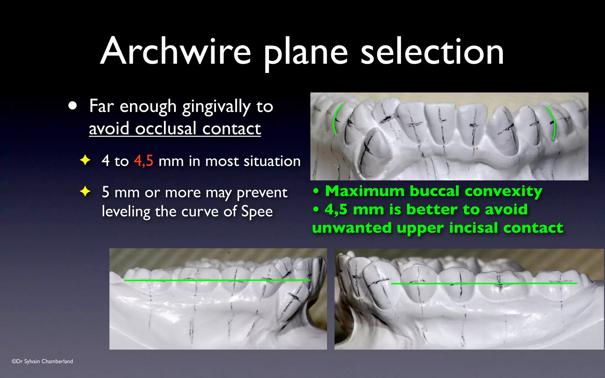
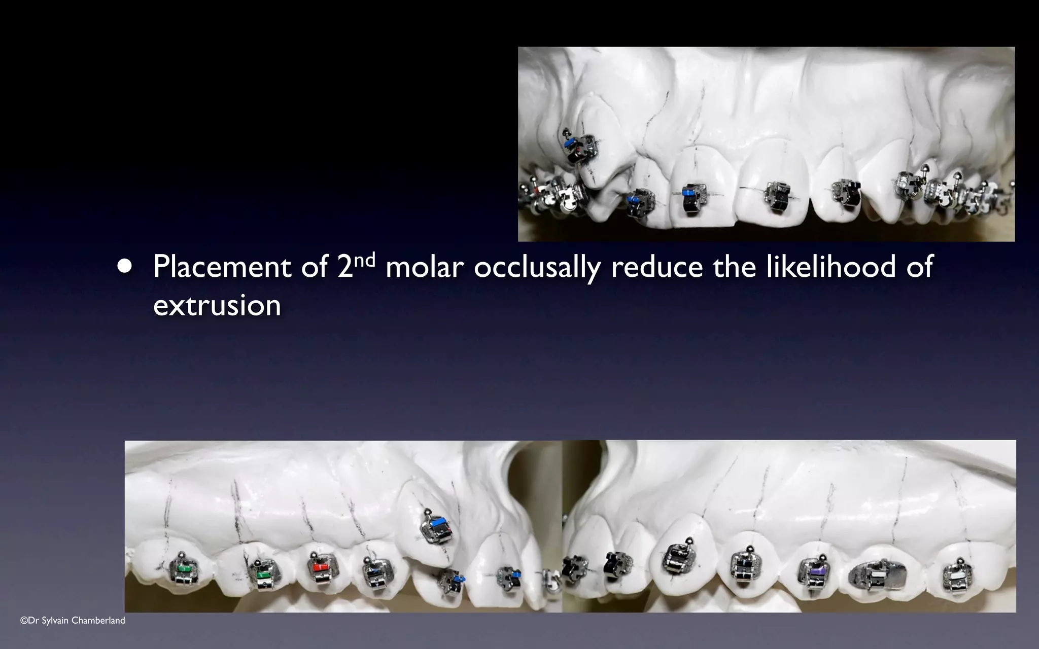
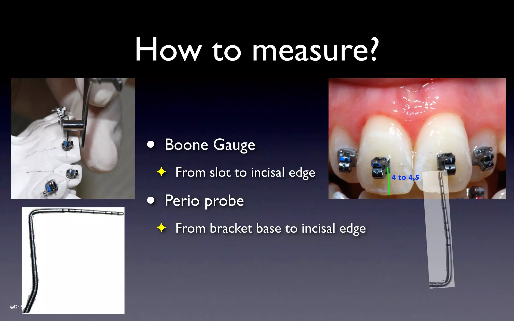
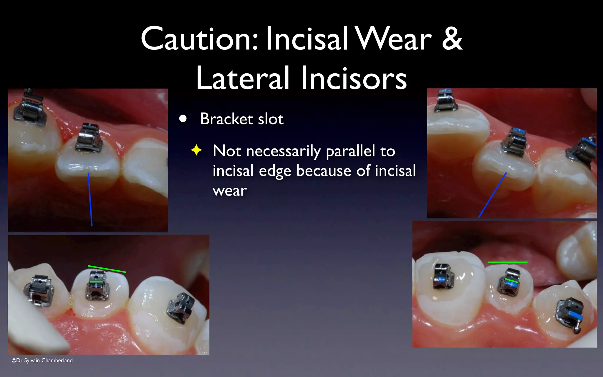
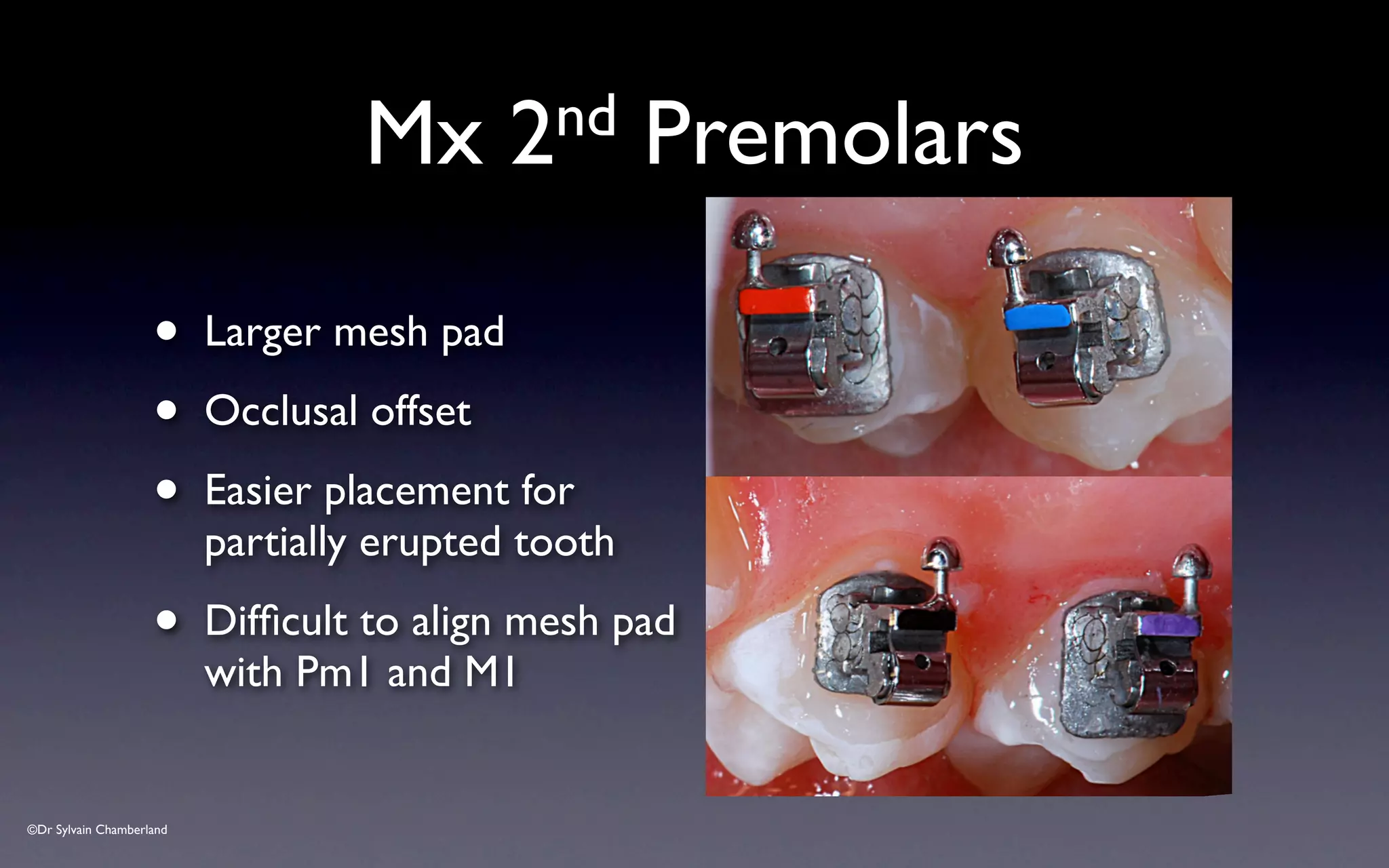
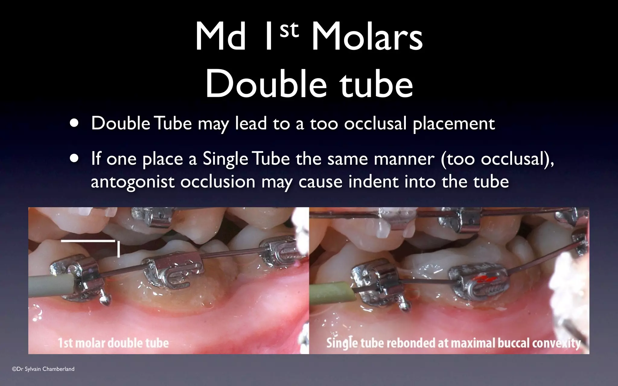
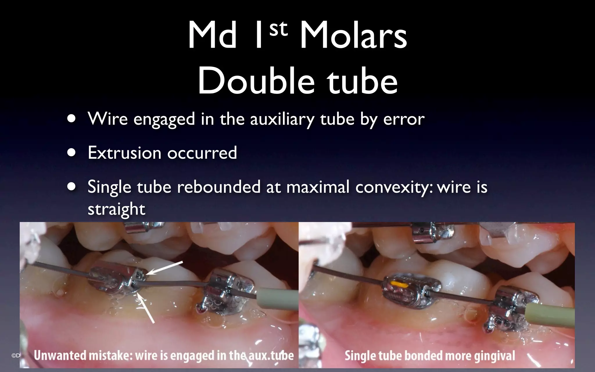
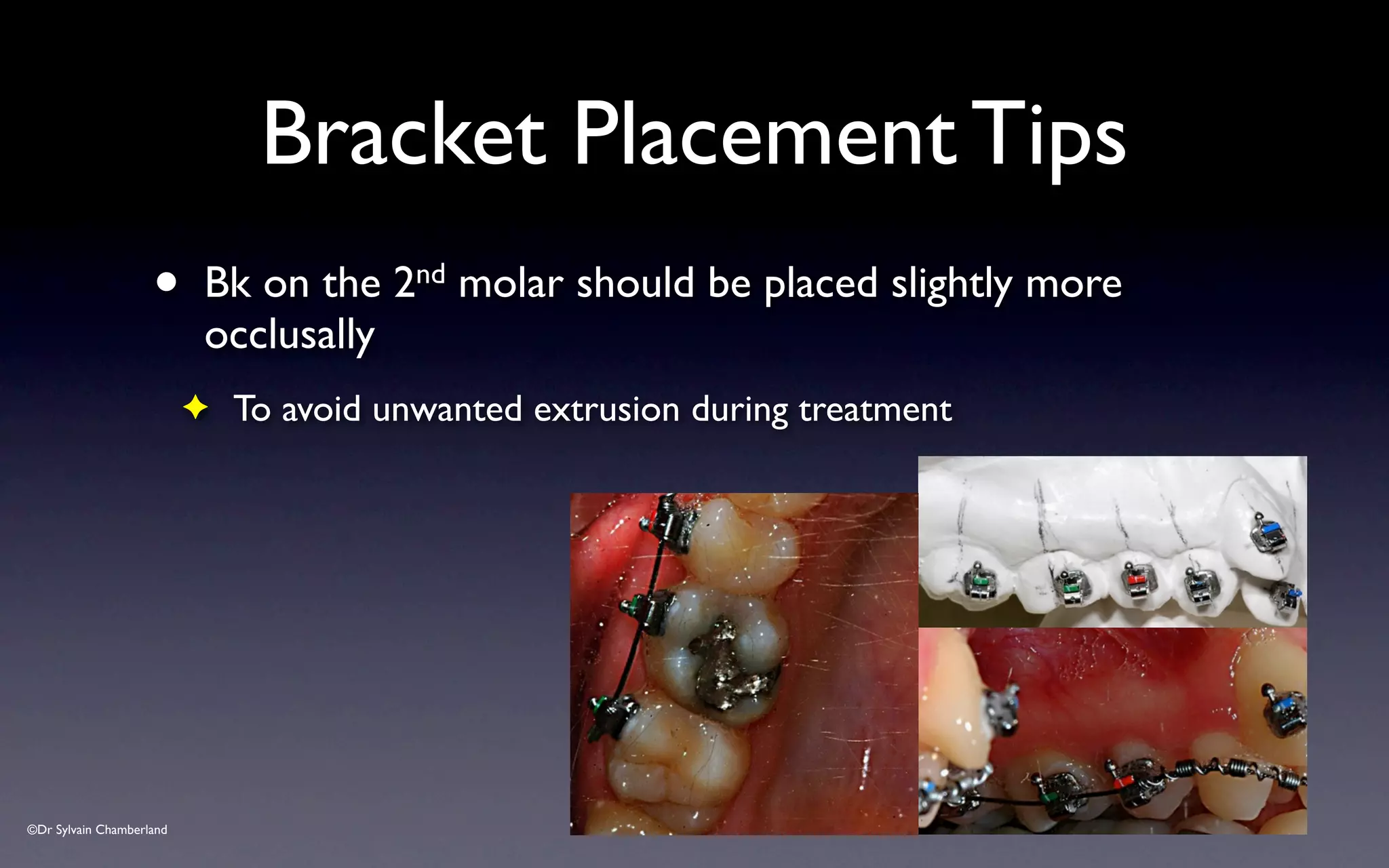
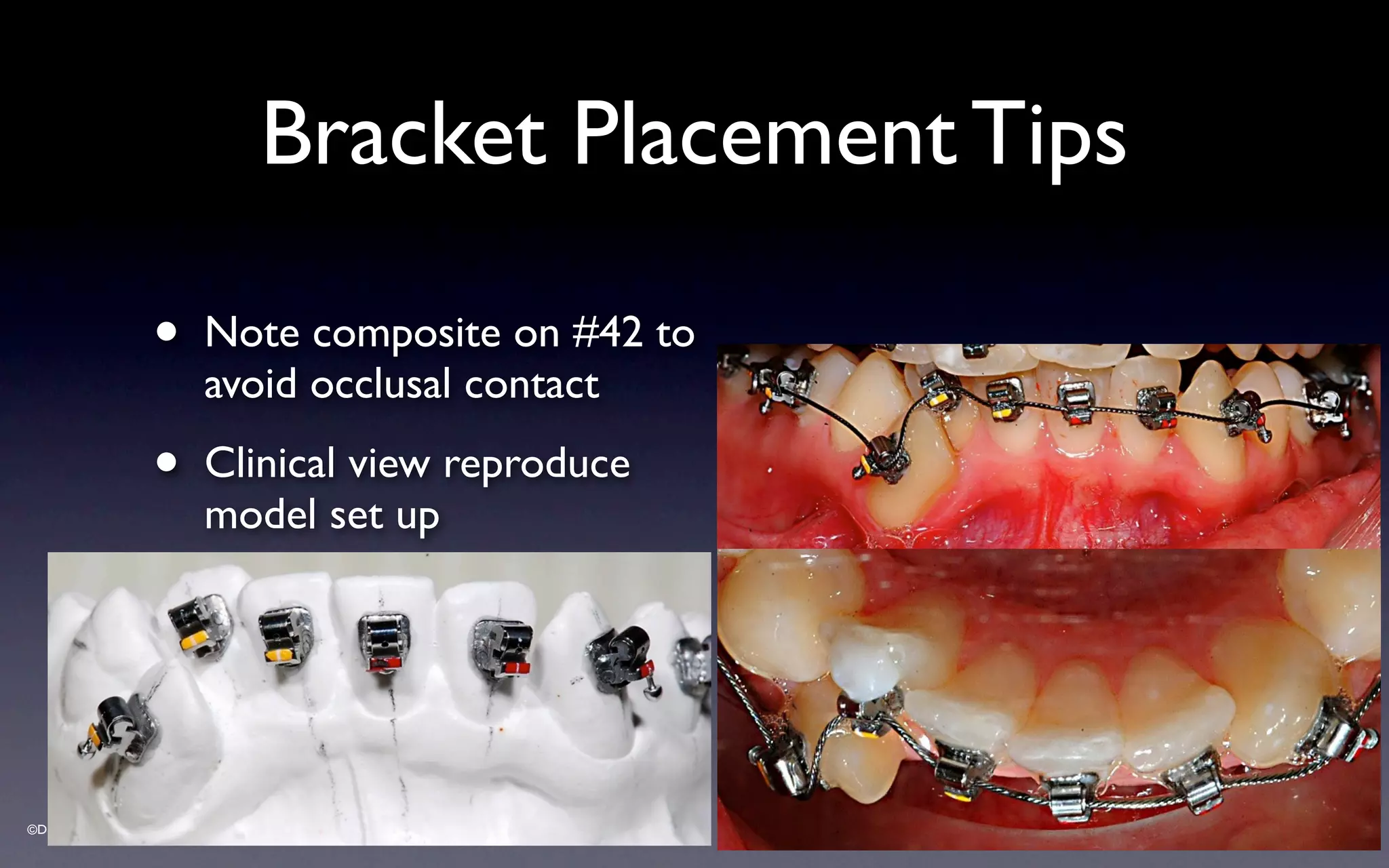
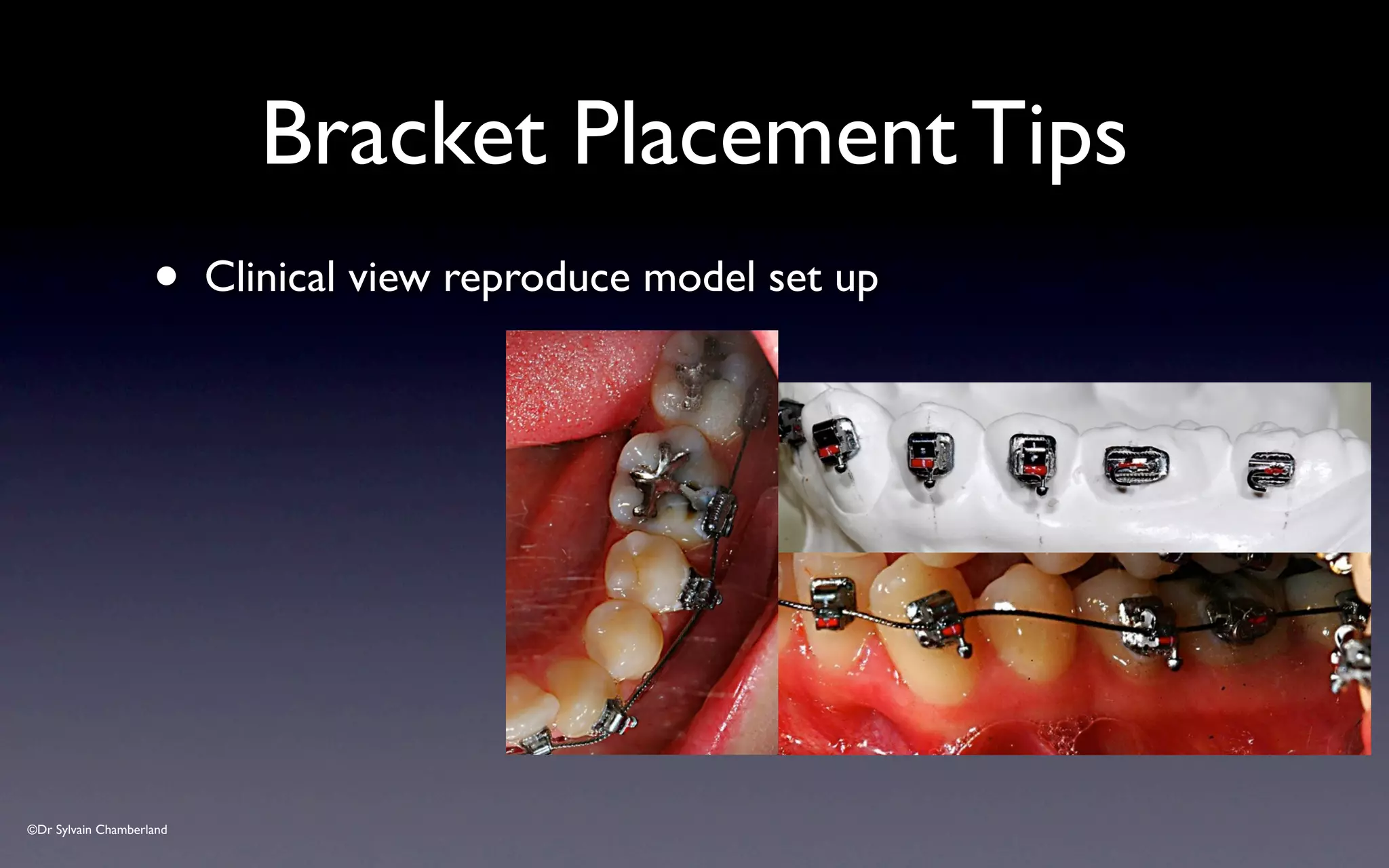
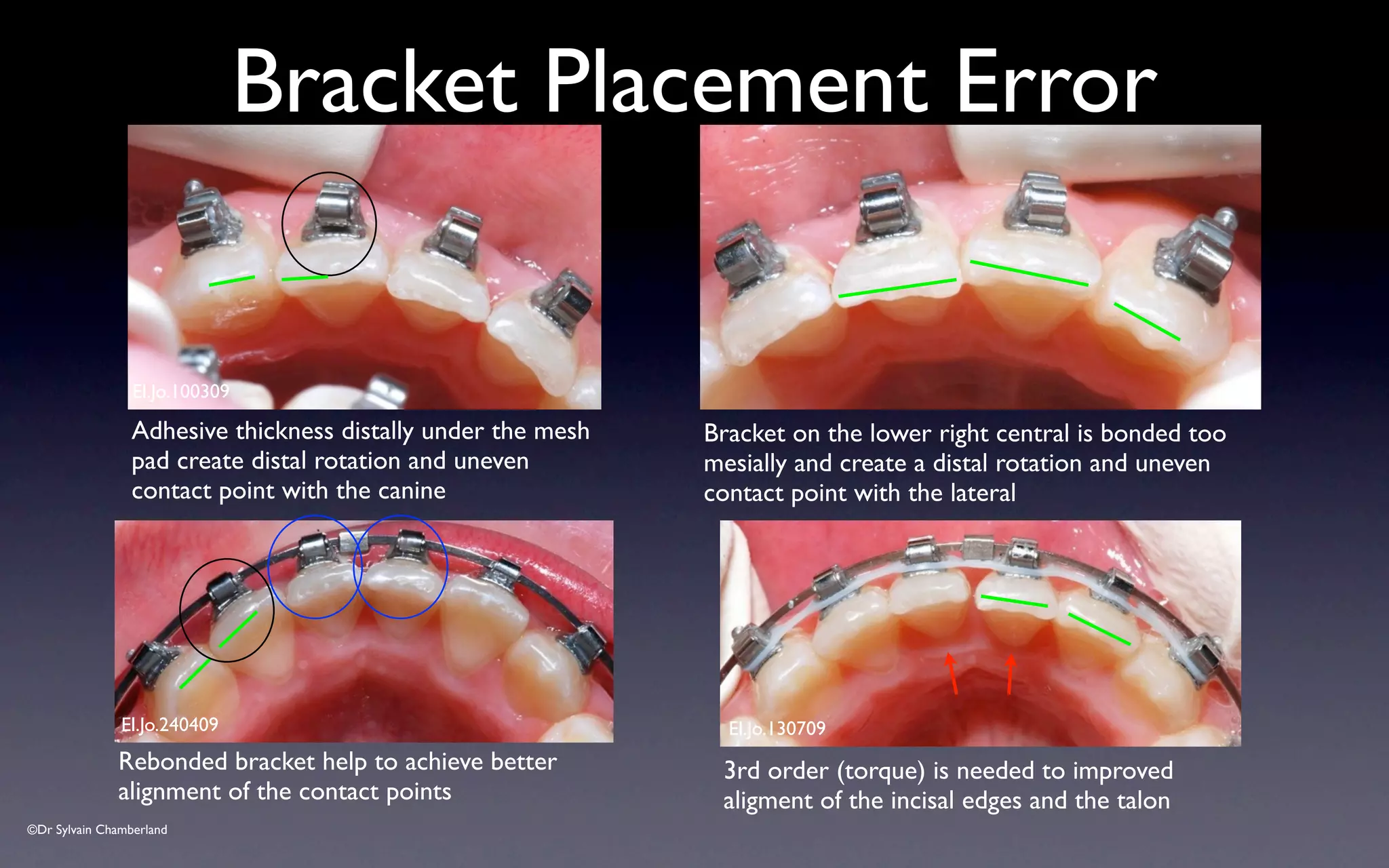
- Proper vertical positioning of brackets is important to avoid occlusal interference.
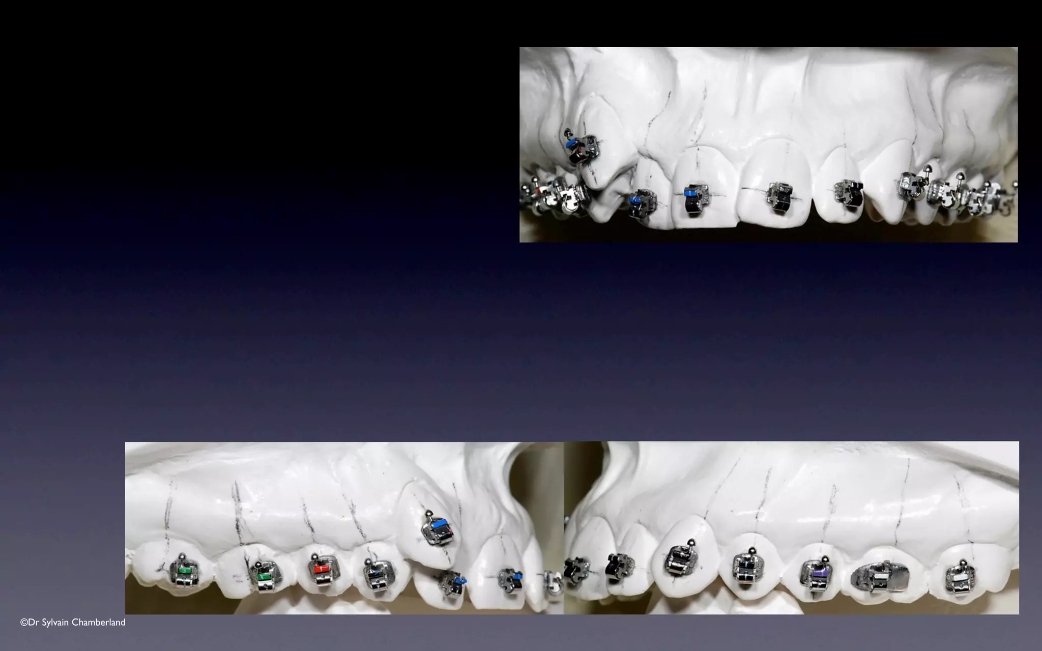
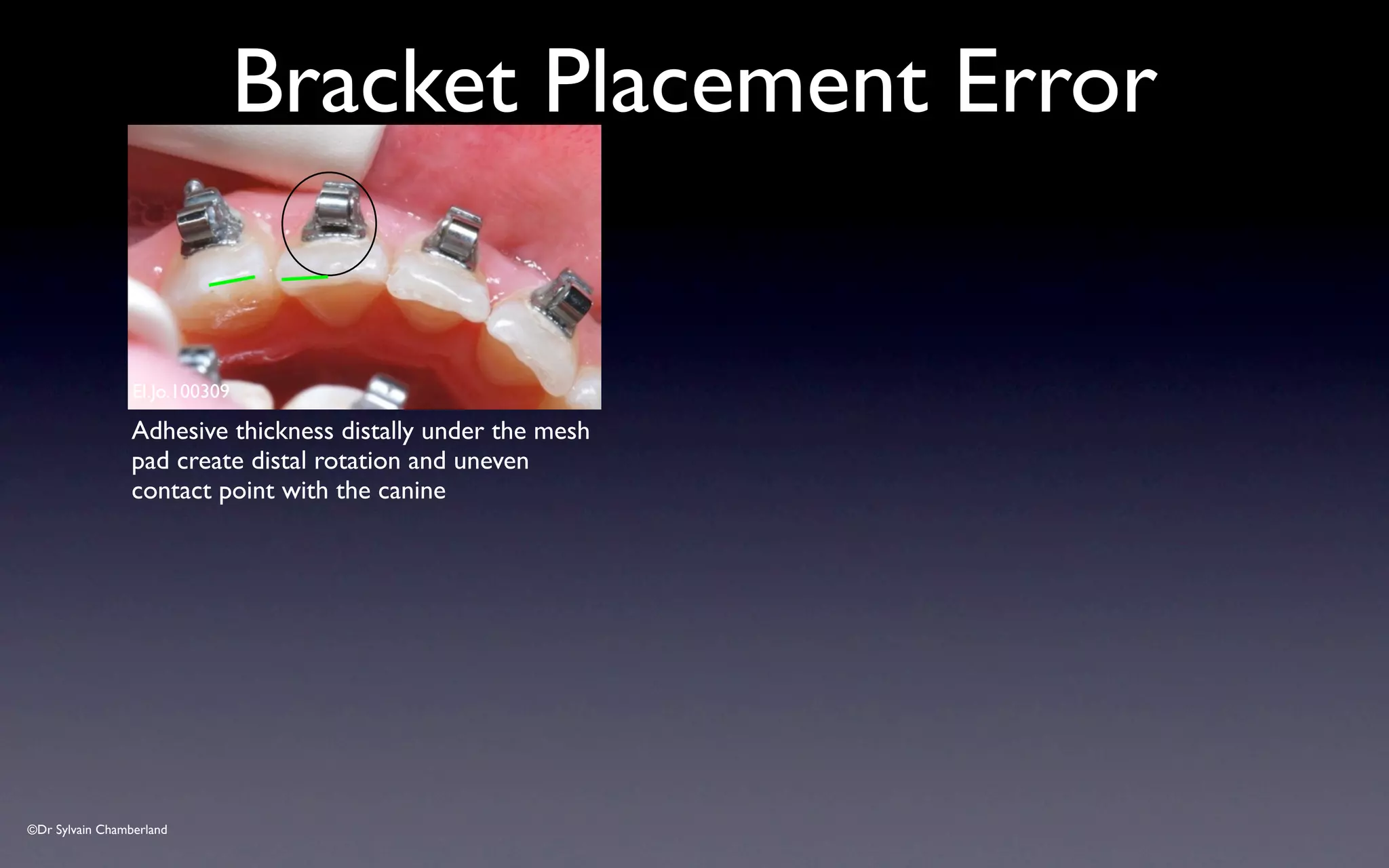
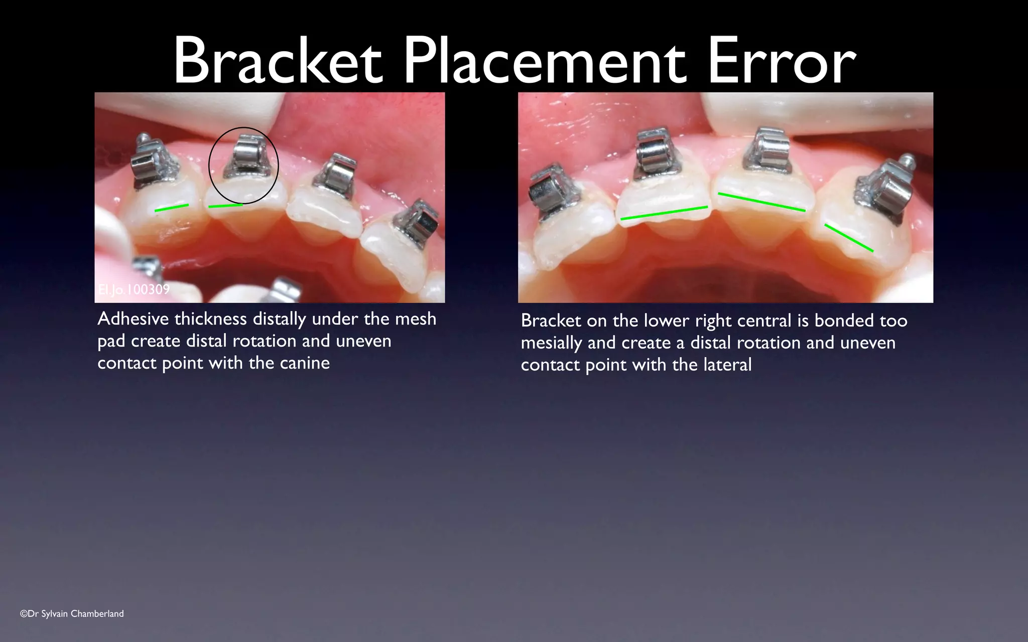
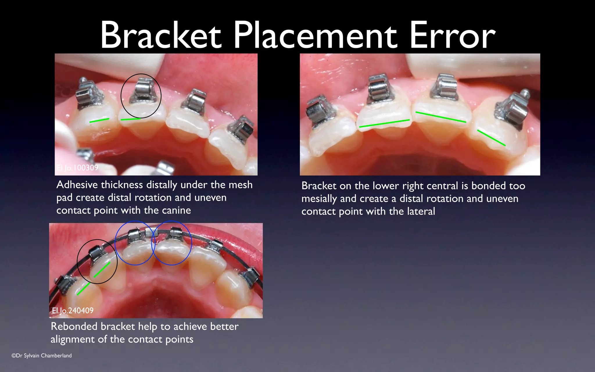
- Common errors in placement like excessive adhesive or incorrect angulation should be avoided or corrected.