Downloaded 14 times
![8 I Scientific Evidence 9IMPLANT I
RESULTS
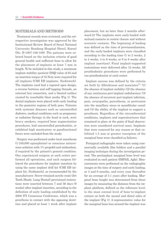
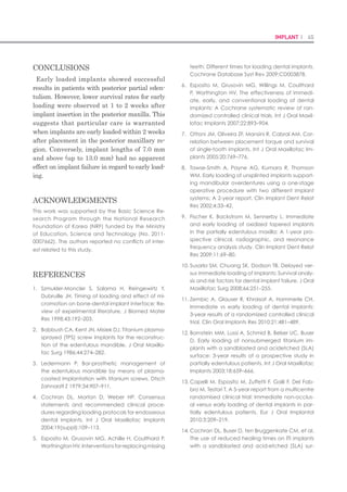
Total 15 implants were placed and were load-
ed immediately. Table I shows the details of
distribution of inserted implants. Marked vari-
ability was noted in the implant sizes selected
for placement, although implants 11.5 mm
length and 5.0 mm diameter were most com-
monly used. The mean follow-up period was 4.8
months (range, 2 to 6 months). Mean marginal
bone loss from implant surgery to immediate
loading, 3-months followup and last follow-up
was found to be 0.03 mm, 0.16 mm and 0.29
mm respectively (Table II). No implant failed
up to 6 months after insertion, resulting in a
100% survival rate.
DISCUSSION
All the inserted implants showed successful
integration and stable peri-implant condition
up to six months. Primary stability was report-
ed to be the most important determining factor
on immediate implant loading.6
Micromove-
ments of more than 100 μm were sufficient to
jeopardize healing with direct bone-to-implant
contact.6
Szmukler-Moncler et al. indicated that
micromotions at the bone-implant interface be-
yond 150 μm resulted in fibrous encapsulation
instead of osseointegration.11
If the primary
implant stability could not be achieved or was
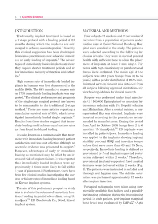
Diameter (mm) Length (mm) No. of Implants
7 8.5 10.0 11.5 13
3.5 0 0 1 3 0 4
4.0 1 0 0 0 0 1
5.0 3 1 0 2 4 10
No. of implants 4 1 1 5 4 15
Table I. Distribution of implant dimensions
Time No. of implants Marginal bone loss
(Mean ± SD) (mm)
Early loading 15 0.03 ± 0.07
3-months follow-up 15 0.16 ± 0.17
Last follow-up 15 0.29 ± 0.19
Table II. Marginal bone loss at early loading, 3-months follow-
up and last follow-up
questionable, it was strongly recommended to
follow a conventional treatment protocol.6
Most
agreed that an insertion torque of at least 32
Nm and a resonance frequency analysis of at
least 60 ISQ was required to achieve a high
level of stability.12
In this study, mean ISQ of 15
early loaded implants was 64.9 ± 4.9.
Generally, clinicians agreed that the quality of
bone was significant for success in immediate
loading. The initial stability of the implant re-
duces in the first 3-6 weeks after placement due
to remodeling and an increased ratio of woven
to lamellar bone.12
Barewal et al. indicated that
implants placed in areas of high bone quality
are relatively stable over the early healing pe-
riods.13
However, we reported that both maxil-
lary and mandibular arches showed no failure
of implants although the sample size was too
small to analyze the data. Horiuchi etal. also
reported about no difference in the success rate
between arches in immediate loading.14
Fur-
ther studies are required about the relationship
between bone quality and the success rate of
immediate loading.
It has been established that there are no ab-
solute contraindications to implant placement
although a number of conditions exist, which
are associated with an increased risk of failure.
12
Tobacco was reported to be only a risk factor
for the implant failure.3
However, the results of
this investigation showed there was no implant
failure in the participating patients who were
smokers. Long-term studies about relevance of
smoking to early loading are necessary.
There were some limitations associated with
this study. The number of investigated im-
plants was insufficient to analyze the data us-
ing proper statistics. The follow-up period was
also short. Therefore, we could not assess the
long-term outcome of immediate loading. Fur-
ther controlled clinical studies are needed to
evaluate the long-term success of early loaded
implants.
CONCLUSION
Within the limitation of this clinical study the
preliminary results indicate that immediate
loading of the implants in partial edentulism,
based on SinusQuickTM
EB implant system,
may be successful for short period up to six
months. Well-controlled long term clinical stud-
ies with large sample size are necessary.
ACKNOWLEDGEMENTS
The authors appreciate the financial help for this
clinical research from Neobiotech Co., Korea.
REFERENCES
Adell R, Lekholm U, Rockler B, Brånemark P. A1.
15-year study of osseointegrated implants in the
treatment of the edentulous jaw. Int J Oral Surg
1981;10:387-416.
Chiapasco M, Gatti C, Rossi E, Haefliger W, Mark-2.
walder TH. Implant-retained mandibular over-
dentures with immediate loading. A retrospec-
tive multicenter study on 226 consecutive cases.
Clin Oral Implants Res 1997;8:48-57.
Susarla SM, Chuang SK, DodsonTB. Delayed ver-3.
sus immediate loading of implants: survival analy-
sis and risk factors for dental implant failure. J Oral
Maxillofac Surg 2008;66:251-5.
Babbush CA, Kent JN, Misiek DJ. Titanium plasma-4.
sprayed (TPS) screw implants for the reconstruc-
tion of the edentulous mandible. J Oral Maxillo-
fac Surg 1986;44:274-82.
Henry P, Rosenberg I. Single-stage surgery for5.
rehabilitation of the edentulous mandible: pre-
liminary results. Pract Periodontics Aesthet Dent
1994;6:15-22.
Calandriello R, Tomatis M. Immediate Occlusal6.
Loading of Single Lower Molars Using Brånemark
System(R) Wide Platform TiUnite Implants: A 5-Year
Follow-Up Report of a Prospective Clinical Multi-
center Study. Clin Implant Dent Relat Res 2009.
[Epub ahead of print].
MalóP, Rangert B, Dvärsäater L. Immediate func-7.
tion of Brånemark implants in the esthetic zone:
a retrospective clinical study with 6 months to 4
years of follow-up. Clin Implant Dent Relat Res
2000;2:138-46.
Attard NJ, Zarb GA. Immediate and early implant8.
loading protocols: a literature review of clinical
studies. J Prosthet Dent 2005;94:242-58.
Misch CE, Wang HL, Misch CM, Sharawy M, Lem-9.
ons J, Judy KW. Rationale for the application of
immediated load in implant dentistry: Part I. Im-
plant Dent 2004;13:207-17.
Hobo S, Ichida E, Garcia LT. Osseointegration and10.
occlusal rehabilitation. Tokyo: Quintessence Pub-
lishing Co., Ltd.; 1989.
Szmukler-Moncler S, Salama H, Reingewirtz Y, Du-11.
bruille JH. Timing of loading and effect of micro-
motion on bone-dental implant interface: review
of experimental literature. J Biomed Mater Res
1998;43:192-203.
Henry PJ, Liddelow GJ. Immediate loading of12.
dental implants. Aust Dent J 2008;53:S69-81.
Barewal RM, Oates TW, Meredith N, Cochran DL.13.
Resonance frequency measurement of implant
stability in vivo on implants with a sandblasted
and acid-etched surface. Int J Oral Maxillofac
Implants 2003;18:641-51.
Horiuchi K, Uchida H, Yamamoto K, Sugimura M.14.
Immediate loading of Brånemark system implants
following placement in edentulous patients:
a clinical report. Int J Oral Maxillofac Implants
2000;15:824-30.
Corresponding author: In-Sung Yeo
Department of Prosthodontics, Section of Dentistry, Seoul National University Bundang Hospital, 300 Gumi-
dong, Bundang-gu, Seongnam-si, Gyeonggi-do, Korea / Tel: +82 31 787 2780; e-mail: yuriphin@chol.com
Received October 23, 2009 / Last Revision November 4, 2009 / Accepted November 9, 2009](https://image.slidesharecdn.com/20160222articlecollection-160412000004/85/20160222-Neobiotech-article-collection-5-320.jpg)
![28 I Scientific Evidence 29IMPLANT I
Sennerby L, Meredith N. Implant stability mea-6.
surements using resonance frequency analysis:
biological and biomechanical aspects and clini-
cal implications. Periodontol 2000 2008;47:51-66.
Jaffin RA, Berman CL. The excessive loss of Brane-7.
mark fixtures in type IV bone: a 5-year analysis. J
Periodontol 1991;62:2-4.
Balshi TJ, Lee HY, Hernandez RE. The use of ptery-8.
gomaxillary implants in the partially edentulous
patient: a preliminary report. Int J Oral Maxillofac
Implants 1995;10:89-98.
Balshi TJ, Wolfinger GJ, Balshi SF. Analysis of 3569.
pterygomaxillary implants in edentulous arches
for fixed prosthesis anchorage. Int J Oral Maxillo-
fac Implants 1999;14:398-406.
Herrmann I, Lekholm U, Holm S, Kultje C. Evalua-10.
tion of patient and implant characteristics as po-
tential prognostic factors for oral implant failures.
Int J Oral Maxillofac Implants 2005;20:220-30.
Friberg B, Ekestubbe A, Sennerby L. Clinical out-11.
come of Brånemark system implants of various
diameters: a retrospective study. Int J Oral Maxil-
lofac Implants 2002;17:671-7.
Nedir R, Nurdin N, Szmukler-Moncler S, Bischof12.
M. Placement of tapered implants using an os-
teotome sinus floor elevation technique without
bone grafting: 1-year results. Int J Oral Maxillofac
Implants 2009;24:727-33.
Nedir R, Bischof M, Vazquez L, Nurdin N, Szmukler-13.
Moncler S, Bernard JP. Osteotome sinus floor el-
evation technique without grafting material:
3-year results of a prospective pilot study. Clin
Oral Implants Res 2009;20:701-7.
Crespi R, Capparè P, Gherlone E. Osteotome sinus14.
floor elevation and simultaneous implant place-
ment in grafted biomaterial sockets: 3 years of
follow-up. J Periodontol 2010;81:344-9.
Ivanoff CJ, Gröndahl K, Bergström C, Lekholm U,15.
Brånemark PI. Influence of bicortical or mono-
cortical anchorage on maxillary implant stabil-
ity: a 15-year retrospective study of Brånemark
system implants. Int J Oral Maxillofac Implants
2000;15:103-10.
Summers RB. A new concept in maxillary implant16.
surgery: the osteotome technique. Compendium
1994;15:152-8.
Blanco J, Suárez J, Novio S, Villaverde G, Ramos I,17.
Segade LA. Histomorphometric assessment in hu-
man cadavers of the periimplant bone density in
maxillary tuberosity following implant placement
using osteotome and conventional techniques.
Clin Oral Implants Res 2008;19:505-10.
Büchter A, Kleinheinz J, Wiesmann HP, Kersken J,18.
Nienkemper M, Weyhrother H, et al. Biological
and biomechanical evaluation of bone remodel-
ing and implant stability after using an osteotome
technique. Clin Oral Implants Res 2005;16:1-8.
Fanuscu MI, Chang TL, Akça K. Effect of surgical19.
techniques on primary implant stability and peri-
implant bone. J Oral Maxillofac Surg 2007;65:2487-
91.
Proff P, Bayerlein T, Rottner K, Mai R, Fanghänel20.
J, Gedrange T. Effect of bone conditioning on
primary stability of FRIALIT-2 impalts. Clin Oral Im-
plants Res 2008;19:42-7.
Nkenke E, Lehner B, Fenner M, Roman FS, Thams21.
U, Neukam FW, et al. Immediate versus delayed
loading of dental implants in the maxillae of
minipigs: follow-up of implant stability and implant
failures. Int J Oral Maxillofac Implants 2005;20:39-
47.
Weber HP, Morton D, Gallucci GO, Roccuzzo M,22.
Cordaro L, Grutter L. Consensus statements and
recommended clinical procedures regarding
loading protocols. Int J Oral Maxillofac Implants
Suppl 2009;24:180-3.
Tabassum A, Meijer GJ, Wolke JG, Jansen JA.23.
Influence of the surgical technique and surface
roughness on the primary stability of an implant in
artificial bone with a density equivalent to maxil-
lary bone: a laboratory study. Clin Oral Implants
Res 2009;20:327-32.
Chang PC, Lang NP, Giannobile WV. Evaluation24.
of functional dynamics during osseointegration
and regeneration associated with oral implants.
Clin Oral Implants Res 2010;21:1-12.
Aparico C, Lang NP, Rangert B. Validity and clini-25.
cal significance of biomechanical testing of im-
plant/bone interface. Clin Oral Implants Res Sup-
pl.2 2006;17:2-7.
Nkenke E, Hahn M, Weinzierl K, Radespiel- Tröger26.
M, Neukam FW, Engelke K. Implant stability and
histomorphometry: a correlation study in human
cadavers using stepped cylinder implants. Clin
Oral Implants Res 2003;14:601-9.
Akkocaoglu M, Uysal S, Tekdemir l, Akca K, Cehreli27.
MC. Implant design and intraosseous stability of
immediately placed implants: a human cadaver
study. Clin Oral Implants Res 2005;16:202-9.
da Cunha HA, Francischone CE, Filho HN, de Ol-28.
iveira RC. A comparison between cutting torque
and resonance frequency in the assessment
of primary stability and final torque capacity of
standard and TiUnite single-tooth implant under
immediate loading. Int J Oral Maxillofac Implants
2004;19:578-85.
Akça K, Akkocaoglu M, Cömert A, Tekdemir I,29.
Cehreli MC. Bone strains around immediately
loaded implants supporting mandibular over-
dentures in human cadavers. Int J Oral Maxillofac
Implants 2007;22:101-9.
Devlin H, Homer K, Ledgerton D. A comparison of30.
maxillary and mandibular bone mineral densities.
J Prosthet Dent 1998;79:323-7.
Miyamoto I, Tsuboi Y, Wada E, Suwa H, Iizuka T.31.
Influence of cortical bone thickness and implant
length on implant stability at the time of surgery-
-clinical, prospective, biomechanical, and imag-
ing study. Bone 2005;37:776-80.
Cakur B, Sümbüllü MA, Durna D. Relationship32.
among schneiderian membrane, Underwood’s
septa, and maxillary sinus inferior border. Clin Im-
plant Dent Relat Res 2011 Apr 19. [Epub ahead
of print]
Wennerberg A, Albrektsson T, Johansson C, An-33.
dersson B. Experimental study of turned and grit-
blasted screw-shaped implants with special em-
phasis on effects of blasting material and surface
topography. Biomaterials 1996;17:15-22.
Wennerberg A, Albrektsson T, Lausmaa J. Torque34.
and histomorphometric evaluation of c.p. tita-
nium screws blasted with 25- and 75-microns-
sized particles of Al2O3. J Biomed Mater Res
1996;30:251-60.
Piattelli M, Scarano A, Paolantonio M, Iezzi G,35.
Petrone G, Piattelli A. Bone response to machined
and resorbable blast material titanium implants:
an experimental study in rabbits. J Oral Implantol
2002;28:2-8.
Tabassum A, Meijer GJ, Wolke JG, Jansen JA.36.
Influence of surgical technique and surface
roughness on the primary stability of an implant
in artificial bone with different cortical thick-
ness: a laboratory study. Clin Oral Implants Res
2010;21:213-20.
Shalabi MM, Wolke JG, Jansen JA. The effects37.
of implant surface roughness and surgical tech-
nique on implant fixation in an in vitro model. Clin
Oral Implants Res 2006;17:172-8.
Shalabi MM, Wolke JG, de Ruijter AJ, Jansen JA. A38.
mechanical evaluation of implants placed with
different surgical techniques into the trabecular
bone of goats. J Oral Implantol 2007;33:51-8.
Jun SH, Chang BM, Weber HP, Kwon JJ. Compari-39.
son of initial stability parameters and histomor-
phometric analysis of implants inserted into ex-
traction sockets: human fresh cadaver study. Int
J Oral Maxillofac Implants 2010;25:985-90.
Corresponding author: Dr Richard Leesungbok, Department of Biomaterials &
Prosthodontics, Kyung Hee University Dental Hospital at Gangdong, Sangil-Dong
149, Kangdong-Gu, Seoul134-727 KOREA
Fax: +82-2-440-7549 / E-mail: sbykmw@yahoo.co.kr](https://image.slidesharecdn.com/20160222articlecollection-160412000004/85/20160222-Neobiotech-article-collection-15-320.jpg)
![72 I Scientific Evidence 73IMPLANT I
tained by buccolingually measuring the length
from the boundary portion between the implant
collar and suture thread to the first boneim-
plant contact (fBIC).
2.5 Statistical Analysis
We used SPSS version 17.0 (SPSS, Chicago,
IL, USA) for all statistical analyses. ANOVA
was used to compare groups. If ANOVA indi-
cated significant differences between groups,
multiple comparison analysis was performed
using the Scheffe & Bonferroni test as a post-
hoc test.
3. Results
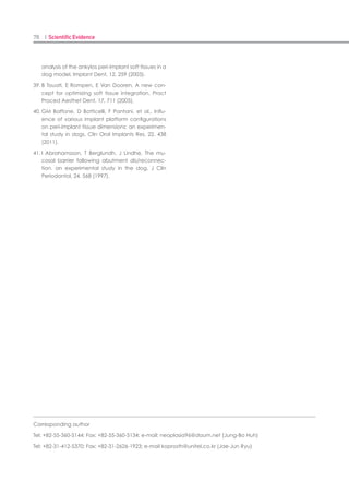
3.1 Radiographic Analysis
Mesiodistal marginal bone resorption capaci-
ties are shown in Table 2. No differences were
observed between groups at any X-ray point (p
> 0.05). A representative X-ray radiograph of
each group is shown in Fig 5. The resorption
capacity of the mesiodistal marginal bone did
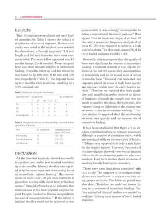
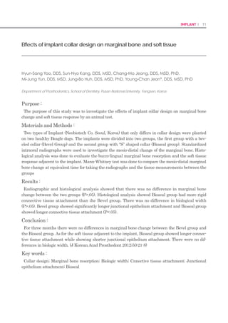
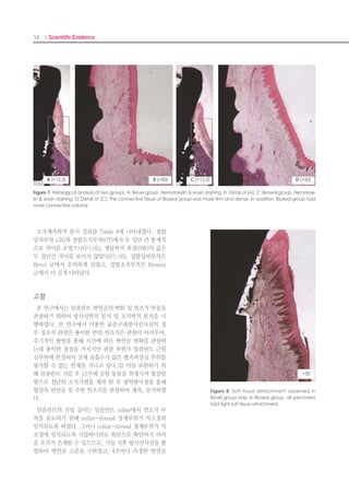
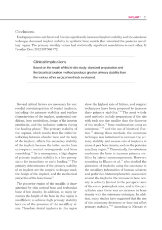
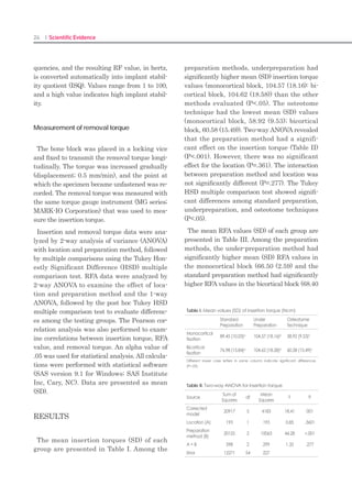
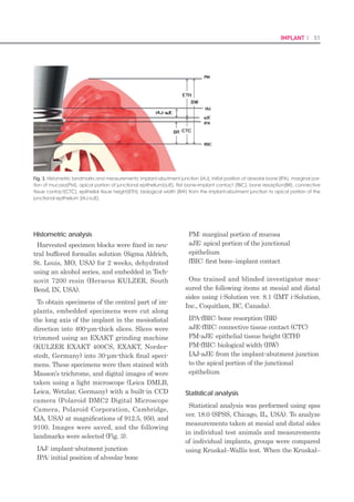
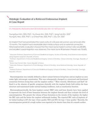
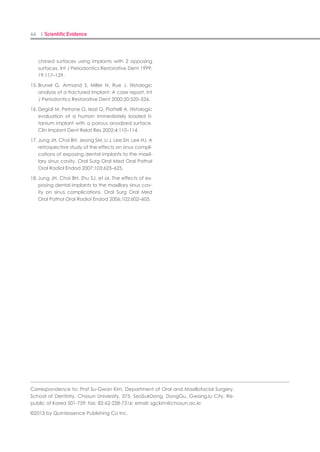
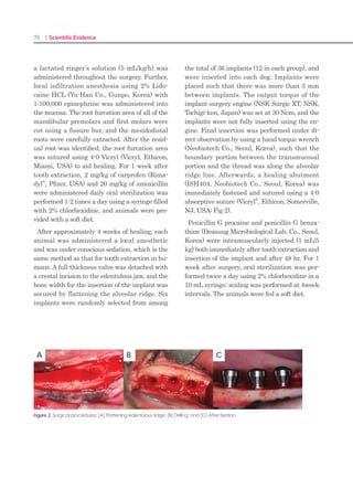
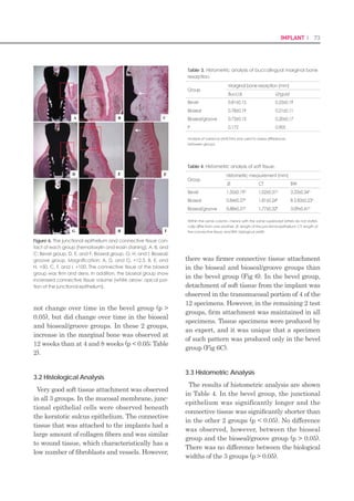
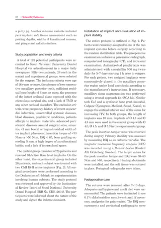
Figure 4. Histometric measurement. PM: marginal portion of
the mucosa; aS: apical extension of the sulcus; aJE: apical
portion of the junctional epithelium, fBIC: first bone-implant
contact; JE: length of the junctional epithelium (aS/aJE); CT:
length of the connective tissue (aJE/fBIC); and BW: biological
width (PM/fBIC).
Figure 5. Radiographic analysis of each group. (A) Bevel
group; (B) Bioseal group; and (C) Bioseal/groove group. The
white arrows indicate the mesiodistal marginal bone level.
Images were obtained from the same specimen in the same
group by period. Bone resorption was observed at 4 weeks
after surgery in all the groups, but bone increased again by12
weeks after surgery.
Table 2. Mesiodistal marginal bone resorption, as deter-
mined by radiographic analysis.
Group
Marginal bone resorption (mm)
Week 4 Week 8 Week 12
Bevel 0.36±0.29aA
0.34±0.31aA
0.18±0.10aA
Bioseal 0.45±0.24aA
0.36±0.22aA
0.07±0.07aB
Bioseal/groove 0.39±0.21aA
0.31±0.29aA
0.08±0.05aB
Different lowercase letters in the same column indicate significant differences
between the bevel and bioseal groups at the same time (analysis of variance
[ANOVA]; p < 0.05).
Different uppercase letters in the same row indicate significant differences over
time using the Kruskal–Wallis test with the Duncan post-hoc test (p<0.05).
A
B
C
not change over time in the bevel group (p >
0.05), but did change over time in the bioseal
and bioseal/groove groups. In these 2 groups,
increase in the marginal bone was observed at
12 weeks than at 4 and 8 weeks (p < 0.05; Table
2).
3.2 Histological Analysis
Very good soft tissue attachment was observed
in all 3 groups. In the mucosal membrane, junc-
tional epithelial cells were observed beneath
the keratotic sulcus epithelium. The connective
tissue that was attached to the implants had a
large amount of collagen fibers and was similar
to wound tissue, which characteristically has a
low number of fibroblasts and vessels. However,
there was firmer connective tissue attachment
in the bioseal and bioseal/groove groups than
in the bevel group (Fig 6). In the bevel group,
detachment of soft tissue from the implant was
observed in the transmucosal portion of 4 of the
12 specimens. However, in the remaining 2 test
groups, firm attachment was maintained in all
specimens. Tissue specimens were produced by
an expert, and it was unique that a specimen
of such pattern was produced only in the bevel
group (Fig 6C).
3.3 Histometric Analysis
The results of histometric analysis are shown
in Table 4. In the bevel group, the junctional
epithelium was significantly longer and the
connective tissue was significantly shorter than
in the other 2 groups (p < 0.05). No difference
was observed, however, between the bioseal
group and the bioseal/groove group (p > 0.05).
There was no difference between the biological
widths of the 3 groups (p > 0.05).
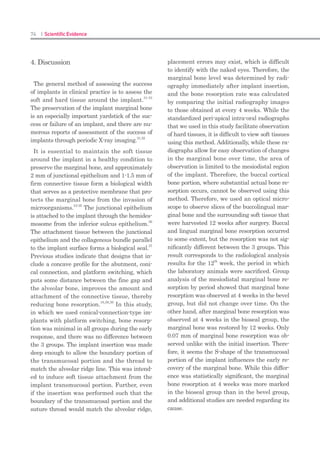
Figure 6. The junctional epithelium and connective tissue con-
tact of each group (hematoxylin and eosin staining). A, B, and
C: Bevel group. D, E, and F: Bioseal group. G, H, and I: Bioseal/
groove group. Magnification: A, D, and G, ×12.5. B, E, and
H, ×50. C, F, and I, ×100. The connective tissue of the bioseal
group was firm and dens. In addition, the bioseal group show
increased connective tissue volume (white arrow: apical por-
tion of the junctional epithelium).
Table 3. Histometric analysis of buccolingual marginal bone
resorption.
Group
Marginal bone resorption (mm)
Buccal Lingual
Bevel 0.81±0.15 0.25±0.19
Bioseal 0.78±0.19 0.21±0.11
Bioseal/groove 0.73±0.15 0.20±0.17
P 0.172 0.905
Analysis of variance (ANOVA) was used to assess differences
between groups.
Table 4. Histometric analysis of soft tissue.
Group
Histometric measurement (mm)
JE CT BW
Bevel 1.35±0.19A
1.02±0.31A
3.33±0.34A
Bioseal 0.84±0.27B
1.81±0.24B
B 2.83±0.23A
Bioseal/groove 0.88±0.31B
1.77±0.32B
3.09±0.41A
Within the same column, means with the same superscript letters do not statisti-
cally differ from one another. JE: length of the junctional epithelium; CT: length of
the connective tissue; and BW: biological width](https://image.slidesharecdn.com/20160222articlecollection-160412000004/85/20160222-Neobiotech-article-collection-37-320.jpg)
![84 I Scientific Evidence 85IMPLANT I
Straumann AG (control), IS Non-hex Tempo-
rary Abutment, Neobiotech Co. (experimental)].
Slight occlusal contact was established with
shim stock in maximum bite force, and any
premature contact was avoided in excursions.
Then, periapical radiographs were taken at the
delivery of the prosthesis, and 6 months from
implant insertion.
After 6 months from implant insertion, 17
participants were excluded because they could
not fulfill the protocol standards, and 35 sub-
jects were ready for the final impression stage.
A final impression on the definitive abutments
[RC Cementable Abutment, Institut Strau-
mann AG (control); SCRP Multi Abutment, Ne-
obiotech Co. (experimental)] was made with ad-
ditional polysiloxane in single step with regular
body wash (EmpressTM
Vinyl Polysiloxane Im-
pression Material, 3M ESPE Dental products,
St. Paul, MN, USA) and putty (Exafine Putty
Type, GC Corporation, Tokyo, Japan). On the
day of delivery, the ISQ measurement with the
Osstell device was repeated for each implant.
A definitive fixed screw- and cement-retained
prosthesis (SCRP) was fabricated and delivered
within 2 weeks after making the impression.
The occlusion and lateral contacts were adjust-
ed for the even distribution of the occlusal force
over the fixed prosthesis.
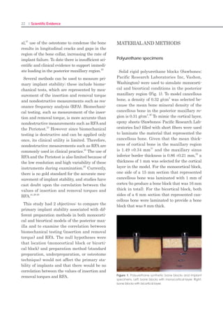
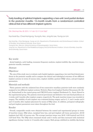
Measurement of marginal bone loss
Marginal bone loss was evaluated using stan-
dard periapical radiographs taken with the use
of a putty jig during surgery and at 4 weeks
and 13 months after the operation (Figs 3 and
4). To obtain the marginal bone level, the en-
largement ratio of each image was calculated
from the manufacturer-specified thread pitch of
0.8 mm that is known for each implant system
used in this study. The distance from the first
thread (reference point) to the level of the alve-
olar bone crest was measured in the mesial and
distal surfaces of the implant and converted to
the actual value using the enlargement ratio.
This value was then compared with the mea-
surement taken at surgery (baseline).
Follow-up procedures and implant success
The patients were scheduled for recall visits
at 9 and 13 months after implant surgery. The
clinical and radiographic examinations were
performed during the follow-up period. The oc-
clusion was checked, and the ISQ values were
measured at the final appointment. In addi-
tion, soft tissue parameters, such as plaque
index, sulcus bleeding index, and widths of
keratinized mucosa (KM), were assessed, and
periapical radiographs were taken.
The following criteria described by Buser et
al. (1997) were applied to evaluate implant
success: (1) the absence of clinically detectable
mobility; (2) the absence of pain or other symp-
toms of discomfort or ongoing pathologic pro-
cesses; (3) the absence of recurrence of peri-im-
plantitis with suppuration; and (4) no evidence
of continuous radiolucency around the implant.
During this follow-up period after the op-
eration, one subject withdrew the consent to
continue participating in the study and four
additional subjects were excluded due to data
missing. As a result, the data from 60 implants
in 30 participants were used for the final statis-
tical analysis of the present study.
Statistical analysis
The statistical analysis comparing the two
groups was performed based on the Per Pro-
tocol (PP) analysis. The chi-square test for
categorical variables and the independent two-
sample t-test or the Mann–Whitney Utest for
continuous variables were used for compara-
tive evaluation depending on the normality of
the distribution. The normality was examined
using the Shapiro–Wilk method. Two-way
repeated-measures analyses of variance in the
general linear model were performed after the
verification of sphericity using the Huynh–
Feldt method to evaluate differences in the
patterns of ISQ change over time. The level of
significance was set at P-value <0.05.
Results
Participants and implant placed
Seventy-six of a total of 128 screened can-
didates were excluded by the entry criteria.
During 6 months after surgery, 17 participants
dropped out because they could not fulfill the
protocol standards. After delivery of definitive
prostheses, one subject withdrew the consent
to continue participating in the study, and
four additional subjects were excluded due to
data missing (Fig. 2). Therefore, the results of
60 implants in 30 patients were examined for
the final analysis of our 13-month randomized
clinical trial.
Demographic characteristics of the partici-
pants
The demographic and clinical characteristics
of the study population for each implant sys-
tem are presented in Table 1. The mean age of
15 patients (22 men and eight women) in the
control group was 62.47 7.83, while the experi-
mental group was composed of 15 patients (18
men and 12 women) with a mean age of 60.53
8.52 years. In both groups, the bone quality
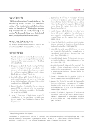
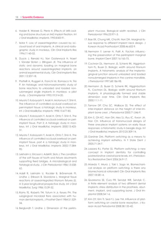
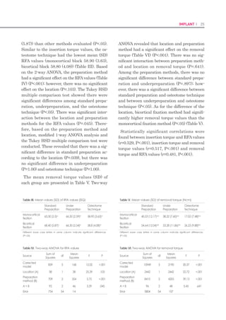
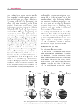
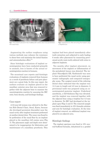
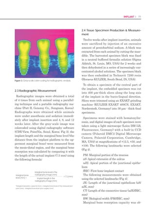
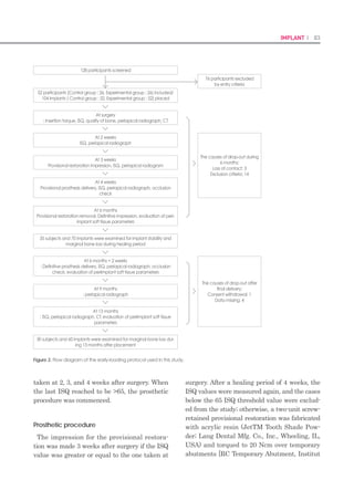
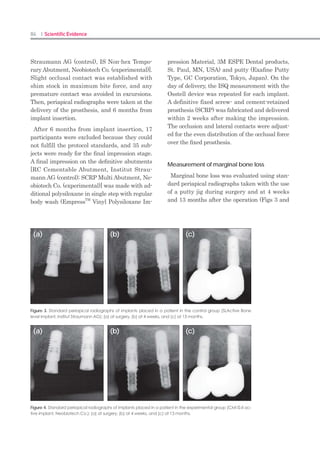
Figure 3. Standard periapical radiographs of implants placed in a patient in the control group (SLActive Bone
level implant, Institut Straumann AG): (a) at surgery, (b) at 4 weeks, and (c) at 13 months.
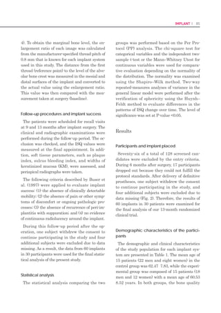
Figure 4. Standard periapical radiographs of implants placed in a patient in the experimental group (CMI IS-II ac-
tive implant, Neobiotech Co.): (a) at surgery, (b) at 4 weeks, and (c) at 13 months.
(a)
(a)
(b)
(b)
(c)
(c)](https://image.slidesharecdn.com/20160222articlecollection-160412000004/85/20160222-Neobiotech-article-collection-43-320.jpg)
![92 I Scientific Evidence 93IMPLANT I
Lekholm, U. & Zarb, G.A. (1985) Patient selection
and preparation. In: Branemark, P.I., Zarb, G.A. &
Albrektsson, T., eds. Tissue Tissue-Integrated Pros-
theses: Osseointegration in Clinical Dentistry, 199–
209. Chicago: Quintessence Publishing Co Inc.
Markovic, A., Colic, S., Scepanovic, M., Misic, T., Ethin-
ic, A. Bhusal, D.S. (2014) A 1-year prospective
clinical and radiographic study of early-loaded
bone level implants in the posterior maxilla. Clini-
cal Implant Dentistry and Related Research doi:
10.1111/cid.12201. [Epub ahead of print].
Meredith, N. (1998) Assessment of implant stability as
a prognostic determinant. The International Jour-
nal of Prosthodontics 11: 491–501.
Morton, D., Bornstein, M.M., Wittneben, J.G., Martin,
W.C., Ruskin, J.D., Hart, C.N. Buser, D. (2010)
Early loading after 21 days of healing of non-
submerged titanium implants with a chemically
modified sandblasted and acid-etched surface:
two-year results of a prospective two-center
study. Clinical Implant Dentistry and Related Re-
search 12: 9–17.
Roccuzzo, M., Aglietta, M. Cordaro, L. (2009) Im-
plant loading protocols for partially edentulous
maxillary posterior sites. The International Journal
of Oral Maxillofacial Implants 24(Suppl): 147–
157.
Roccuzzo, M. Wilson, T.G., Jr. (2009) A prospective
study of 3 weeks’ loading of chemically modified
titanium implants in the maxillary molar region:
1-year results. The International Journal of Oral
Maxillofacial Implants 24: 65–72.
Schliephake, H., H€uls, A. M€uller, M. (2006) Early
loading of surface modified titanium implants in
the posterior mandible: preliminary results. Ap-
plied Osseointegration Research 5: 56–58.
Schwarz, F., Herten, M., Sager, M., Wieland, M., Dard,
M. Becker, J. (2007) Histological and immuno-
histochemical analysis of initial and early osseous
integration at chemically modified and conven-
tional SLA titanium implants: preliminary results of
a pilot study in dogs. Clinical Oral Implants Re-
search 11: 481–488.
Sennerby, L. Meredith, N. (2008) Implant stabil-
ity measurements using resonance frequency
analysis: biological and biomechanical aspects
and clinical implications. Periodontology 2000 47:
51–66.
Ganeles, J., Zollner, A., Jackowski, J., ten Bruggen-
kate, C., Beagle, J. Guerra, F. (2008) Immedi-
ate and early loading of Straumann implants
with a chemically modified surface (SLActive) in
the posterior mandible and maxilla: 1-year results
from a prospective multicenter study. Clinical
Oral Implants Research 19: 1119–1128.
Geng, J.P., Tan, K.B. Liu, G.R. (2001) Application of
finite element analysis in implant dentistry: a re-
view of the literature. The Journal of Prosthetic
Dentistry 85: 585–598.
Hansson, S. (2003) A conical implant-abutment inter-
face at the level of the marginal bone improves
the distribution of stresses in the supporting bone.
An axisymmetric finite element analysis. Clinical
Oral Implants Research 14: 286–293.
Hasan, I., Bourauel, C., Keilig, L., Stark, H. L€uckerath,
W. (2015) The effect of implant splinting on the
load distribution in bone bed around implantsup-
ported fixed prosthesis with different framework
materials: a finite element study. Annals of Anat-
omy-Anatomischer Anzeiger 199: 43–51.
Huwiler, M.A., Pjetursson, B.E., Bosshardt, D.D., Salvi,
G.E. Lang, N.P. (2007) Resonance frequency
analysis in relation to jawbone characteristics
and during early healing of implant installation.
Clinical Oral Implants Research 18: 275–280.
Kim, J.H., Yang, J.Y., Kim, Y.K., Heo, Y.K. Yeo, I.S.
(2013) Retrospective results of implants for par-
tially edentulous posterior jaws according to time
points of early loading. The International Journal
of Oral Maxillofacial Implants 28: 1293–1299.
Kumar, A.B.T., Khalia, N., Gayathri, G.V., Kumar, B.H.D.
Mehta, D.S. (2013) Peri-implant crestal bone
preservation: where do we stand? The Interna-
tional Journal of Oral Implantology Clinical Re-
search 4: 72–77.
Lai, H.C., Zhang, Z.Y., Wang, F., Zhuang, L.F. Liu, X.
(2008) Resonance frequency analysis of stability
on ITI implants with osteotome sinus floor eleva-
tion technique without grafting: a 5-month pro-
spective study. Clinical Oral Implants Research
19: 469–475.
Lang, N.P., Salvi, G.E., Huynh-Ba, G., Ivanovski, S., Do-
nos, N. Bosshardt, D.D. (2011) Early osseointe-
gration to hydrophilic and hydrophobic implant
surfaces in humans. Clinical Oral Implants Re-
search 22: 349–356.
bone loss in relation to the implant neck surface:
an update. Medicina Oral, Patologia Oral y Ciru-
gia Bucal 16: e365–e368.
Atsumi, M., Park, S.H. Wang, H.L. (2007) Methods
used to assess implant stability: current status. The
International Journal of Oral Maxillofacial Im-
plants 22: 743–754.
Bergkvist, G., Simonsson, K., Rydberg, K., Johansson,
F. Derand, T. (2008) A finite element analysis of
stress distribution in bone tissue surrounding un-
coupled or splinted dental implants. Clinical Im-
plant Dentistry and Related Research 10: 40–46.
Bischof, M., Nedir, R., Szmukler-Moncler, S., Bernard,
J.P. Samson, J. (2004) Implant stability mea-
surement of delayed and immediately loaded
implants during healing. A clinical resonance-
frequency analysis study with sandblasted-ande-
tched ITI implants. Clinical Oral Implants Research
15: 529–539.
Buser, D., Broggini, N., Wieland, M., Schenk, R.K., Den-
zer, A.J., Cochran, D.L., Hoffmann, B., Lussi, A.
Steinemann, S.G. (2004) Enhanced bone appo-
sition to a chemically modified SLA titanium sur-
face. Journal of Dental Research 83: 529–533.
Buser, D., Mericske-Stern, R., Bernard, J.P., Behneke,
A., Behneke, N., Hirt, H.P., Belser, U.C. Lang, N.P.
(1997) Long-term evaluation of nonsubmerged ITI
implants. Part 1: 8-year life table analysis of a pro-
spective multi-center study with 2359 implants.
Clinical Oral Implants Research 8: 161–172.
Cochran, D.L., Morton, D. Weber, H.P. (2004) Con-
sensus statements and recommended clinical
procedures regarding loading protocols for en-
dosseous dental implants. The International Jour-
nal of Oral Maxillofacial Implants 19(Suppl):
109–113.
Esposito, M., Grusovin, M.G., Maghaireh, H. Wor-
thington, H.V. (2013) Interventions for replacing
missing teeth: different times for loading dental
implants. The Cochrane Database of Systematic
Reviews (3): CD003878.
Esposito, M., Grusovin, M.G., Willings, M., Coulthard,
P. Worthington, H.V. (2007) The effectiveness of
immediate, early, and conventional loading of
dental implants: a Cochrane systematic review
of randomized controlled clinical trials. The Inter-
national Journal of Oral Maxillofacial Implants
22: 893–904.
even in the areas of low bone density, as long
as the defined inclusion criteria are met; mini-
mum insertion torque and ISQ of 30 Ncm and
65, respectively. In this study, a high degree
of primary stability appears to be one of the
prerequisites for a successful immediate- or
early-loading procedure as previous literature
has suggested (Meredith 1998; Roccuzzo et al.
2009). Furthermore, the use of splinted im-
plants supporting a two-unit fixed prosthesis
during the osseointegration period may play an
important role in the high success rate of the
procedure by promoting an even stress distri-
bution in the surrounding tissue (Bergkvist et
al. 2008; Shigemitsu et al. 2013; Hasan et al.
2015). However, despite the successful clinical
results of the present study, additional well-
designed randomized controlled clinical trials
with a larger sample size and longer observa-
tion period are needed to further validate this
treatment concept for implants in healed sites
in the posterior maxilla.
Acknowledgement
This research was supported by a grant of the Korea
Health Technology RD Project through the Korea
Health Industry Development Institute (KHIDI), funded
by the Ministry of Health Welfare, Republic of Korea
(Grant Number: HI12C0064).
References
Ahn, S.J., Leesungbok, R., Lee, S.W., Heo, Y.K. Kang,
K.L. (2012) Differences in implant stability associ-
ated with various methods of preparation of the
implant bed: an in vitro study. Journal of Prosthet-
ic Dentistry 107: 366–372.
Akca, K., Chang, T.L., Tekdemir, I. Fanuscu, M.I.
(2006) Biomechanical aspects of initial in-
traosseous stability and implant design: a quanti-
tative micro-morphometric analysis. Clinical Oral
Implants Research 17: 465–472.
Aloy-Prosper, A., Maestre-Ferrın, L., Pe~narrocha-Ol-
tra, D. Pe~narrocha-Diago, M. (2011) Marginal](https://image.slidesharecdn.com/20160222articlecollection-160412000004/85/20160222-Neobiotech-article-collection-47-320.jpg)
![108 I Scientific Evidence 109SINUS I
a safe procedure. This process of making a hole
in the lateral wall is simplified and can be per-
formed without specialized skills. The SLA
technique resolves the burdensome features
of the conventional types of the sinus lateral
approach(Table 3).
References
Kim YK, et al :A new crestal approach for sinus1.
floor elevation: Case reports. The Journal of the
Korean Academy of Implant Dentistry, 28:41,
2009.
Toffler M: Treating the atrophic posterior maxilla2.
by combining short implants with minimally inva-
sive osteotome procedures. Pract Proced Aes-
thet Dent, 18:301, 2006.
Fermergard R, Astrand P: Osteotome sinus floor el-3.
evation and simultaneous placement of implants-
-a 1-year retrospective study with Astra Tech im-
plants. Clin Implant Dent Relat Res, 10:62,2008.
Kolerman R, Barnea E: [Crestal core elevation4.
technique- -case series and literature review ] Re-
fuat Hapeh Vehashinayim, 25: 27, 2008.
Reprint requests to: Su-Gwan Kim
Department of Oral and Maxillofacial Surgery, School of Dentistry, Chosun University,
375, SeoSukDong, DongGu, GwangJu City, Korea. Zip Code: 501-759
Table 3. Advantages of the SLA technique
No Requirement for extensive flap opening: The procedure can•
be performed with a minimal flap opening using the SLA-KIT.
No need for a large window: A stable approach can be com-•
pleted without requiring a large window.
Does not require such instruments as a straight handpiece or•
round bur: Preparation is simplified because the surgeon need
not use a straight handpiece or round bur. Damage to the mem-
brane during window formation can be minimized.
Minimal risk of arterial bleeding during window formation: The•
procedure can be performed while monitoring blood vessels in
the area. Therefore, this is a safe procedure.
Risk of membrane tearing during a window formation: The spe-•
cial shape of the reamer edge minimizes the risk of damage to
the membrane.
Risk of swelling and pain with extensive surgery: The degree of•
swelling and pain can be markedly reduced by minimizing surgi-
cal time and scope.
Lack of confidence with regard to techniques of membrane el-•
evation: Three types of custom-designed elevators can elevate
the membrane both safely and effectively.
Immediate loading with a new concept of maxillary sinus elevation
: S-reamer Osteotome Technique.
Richard Leesungbok(1) FP
, Suk-Won Lee (1), Su-Jin Ahn(1), Young-Ku Heo(2), HoonChang (3)
(1)Dept of Biomaterials Prosthodontics,Schoolof Dentistry, Kyung HeeUniversity,
(2)Global Academy of Osseointegration,
(3) Harmony Dental Clinic
Seoul, Republic of Korea
Background Aim
Once in a while, the malleting osteotome technique arises several post-operative complications such
as discomfort and inner auditory organ damage. Also the possibility of damage on the sinus mem-
brane with excessive fracture of sinus floor still remains.
This report introduced a new maxillary sinus floor elevation technique in which only the inferior cor-
tical wall underneath the sinus would be perforated without tearing of maxillary sinus membrane by
drilling instead of malleting using a rotary instrument, called S-reamer®
(Neobiotec Co., Seoul, Ko-
rea).
The objective of this presentation is to show our scientific and clinical experience related to implant
supported fixed restorations for the partially and fully edentulous jaws including a situation after si-
nus graft with S-reamer osteotome technique, and to assess the survival outcome of immediate load-
ing protocols according to their treatment sequence and selected prosthodontic design.](https://image.slidesharecdn.com/20160222articlecollection-160412000004/85/20160222-Neobiotech-article-collection-55-320.jpg)
![126 I Scientific Evidence 127SINUS I
Discussion
As the membrane integrity is important it is
essential to produce a cavity which will limit
the amount of sinus graft material inserted
into the zone so improving implant survival
and reducing complications.
Ardekian et al. (4) assess the incidence of
membrane perforations, complications, and
successful treatment. They did not find sig-
nificant differences between implant survival
for implants inserted in a grafted sinus where
there was a membrane perforation and sinus
with the membrane intact. However, Prous-
saefs et al. (9) found fewer implant survivals
for implants installed in a grafted sinus with
membrane perforation. Subsequently agreeing
with this author, Hernández-Alfaro et al. (10)
studied the prevalence of surgical complications
and described an action protocol relating to
the perforation size. These authors describe in
their results a lower implant survival rate for
implants installed in grafted sinus when there
was a membrane perforation influenced also by
perforation size. These results coincided with
the results reported by Viña-Almunia et al. (11)
who concluded that the survival of implants
diminishes when they are placed in sinus lifts
with a perforated membrane.
There are different options described in the
literature for preparing the lateral window,
such as conventional osteotomy using rotating
instruments (round burrs), trephines, piezosur-
gery and/or lasers.
Romanos (12) describes a different technique
for window preparation for sinus lift procedure.
A round burr is used to prepare the osteotomy
with continuous saline solution irrigation. Be-
fore the sinus mucosa is visible through the
maxillary bone at the osteotomy site, a mallet
and a dental mirror holder is used to tap in one
blow in a perpendicular direction to the lateral
bony wall, in the middle of the window. The
author was not able to observe any perforation
of the sinus floor mucosa using this technique
in the 56 cases described. However, Sohn et
al. (13) published a study where erbium, chro-
mium, yttrium–scandium–gallium–garnet (Er,
Cr:YSGG) laser and various laser systems were
used for 12 sinus bone grafts in ten patients.
The efficiency of the laser was evaluated ac-
cording to the osteotomy time and the rate of
sinus membrane perforation. The author de-
scribes a perforation ratio of 33.3% and all the
implants placed immediately were successful.
In 2002, Emtiaz et al. (14) published the same
surgical procedure using trephines (Implant In-
novations®, Inc., Ibérica, SL, Barcelona, Spain)
although reference is made to the need for cau-
tion during the lateral osteotomy due to the
membrane perforation risk using a trephine.
The trephine used in this situation (SLA KIT
–Yield® Neobiotech), presents differences from
conventional trephine used. The contact surface
of the new trephine has a curved periphery and
a bone-maintaining area contacting surface.
The bone maintaining area includes a first in-
side wall oriented in a drilling direction higher
than a second inside wall with a drilling sur-
face exposed in the drilling direction prevent-
ing sinus membrane damage when the head
of drill contacts the membrane. The described
technique in this article presents a number of
advantages such as reduced surgical time, a
small and accurate access for sinus lift for a
single implant and lower risk of perforation of
the sinus membrane. Due to the technique of
performing osteotomy with a trephine mounted
in the same handpiece used later for implant
surgery, the use of auxiliary different handpiec-
es or piezoelectric equipment was eliminated,
so reducing the surgical cost.
It can be concluded that in the case described,
the use of trephine drills of the SLA system
mounted in a handpiece allows better access to
lateral approach due to its perpendicular posi-
tion relative to the sinus wall. The shape of the
contact area of the drills minimizes the sinus
membrane perforation risk during osteotomy.
Lateral approach for sinus lifts by this tech-
nique did not present any complications in the
documented case. This method provides greater
confidence and security for the clinician at the
time of the lateral osteotomy, and reduces the
surgical time of this phase.
References
Chanavaz M. Maxillary sinus: anatomy, physiol-1.
ogy, surgery, and bone grafting related to im-
plantology--eleven years of surgical experience
(1979-1990). J Oral Implantol. 1990;16:199-209.
Zijderveld SA, Van den Bergh JP, Schulten EA, Ten2.
Bruggenkate CM. Anatomical and surgical find-
ings and complications in 100 consecutive maxil-
lary sinus floor elevation procedures. J Oral Maxil-
lofac Surg. 2008;66:1426-38.
Raghoebar GM, Batenburg RH, Timmenga NM,3.
Vissink A, Reintsema H. Morbidity and complica-
tions of bone grafting of the floor of the maxillary
sinus for the placement of endosseous implants.
Mund Kiefer Gesichtschir. 1999;3Suppl 1:S65-9.
Ardekian L, Oved-Peleg E, Mactei EE, Peled M.4.
The clinical significance of sinus membrane per-
foration during augmentation of the maxillary si-
nus. J Oral Maxillofac Surg. 2006;64:277-82.
Pikos MA. Maxillary sinus membrane repair: report5.
of a technique for large perforations. Implant
Dent. 1999;8:29-34.
Wallace SS, Mazor Z, Froum SJ, Cho SC, Tarnow6.
DP. Schneiderian membrane perforation rate
during sinus elevation using piezosurgery: clinical
results of 100 consecutive cases. Int J Periodontics
Restorative Dent. 2007;27:413-9.
Stübinger S, Landes C, Seitz O, Zeilhofer HF, Sader7.
R. [Ultrasonic bone cutting in oral surgery: a re-
view of 60 cases]. Ultraschall Med. 2008;29:66-71.
Blus C, Szmukler-Moncler S, Salama M, Salama H,8.
Garber D. Sinus bone grafting procedures using
ultrasonic bone surgery: 5-year experience. Int J
Periodontics Restorative Dent. 2008;28:221-9.
Proussaefs P, Lozada J, Kim J, Rohrer MD. Repair9.
of the perforated sinus membrane with a resorb-
able collagen membrane: a human study. Int J
Oral Maxillofac Implants. 2004;19:413-20.
Hernández-Alfaro F, Torradeflot MM, Marti C.10.
Prevalence and management of Schneiderian
membrane perforations during sinuslift proce-
dures. Clin Oral Implants Res. 2008;19:91-8.
Viña-Almunia J, Peñarrocha-Diago M, Peñar-11.
rocha-Diago M. Influence of perforation of the
sinus membrane on the survival rate of implants
placed after direct sinus lift. Literature update.
Med Oral Patol Oral Cir Bucal. 2009;14:E133-6.
Romanos GE. Window preparation for sinus lift12.
procedures: a simplified technique. Implant Dent.
2008;17:377-81.
Sohn DS, Lee JS, An KM, Romanos GE. Erbium,13.
chromium:yttrium-scandium-gallium-garnet la-
ser-assisted sinus graft procedure. Lasers Med Sci.
2009;24:673-7.
Emtiaz S, Caramês JM, Pragosa A. An alternative14.
sinus floor elevation procedure: trephine osteoto-
my. Implant Dent. 2006;15:171-7.
Correspondence: Medicine, Surgery and Oral Implantology Department. Dental
School. Universitat Internacional de Catalunya Josep Trueta, s/n 08195 Sant Cugat del
Vallès Barcelona.Spain
nuriafarrepages@telefonica.net](https://image.slidesharecdn.com/20160222articlecollection-160412000004/85/20160222-Neobiotech-article-collection-64-320.jpg)

This study evaluated the outcome of immediately loading 15 dental implants in 4 patients over a mean follow-up period of 4.8 months. The mean marginal bone loss from implant surgery to immediate loading was 0.03 ± 0.07 mm, and 0.16 ± 0.17 mm after 3 months of continued loading. No implants failed, resulting in a 100% survival rate. The results suggest that immediate loading of dental implants can achieve high success rates of up to 6 months. However, long-term clinical studies with larger sample sizes are still needed.


