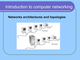
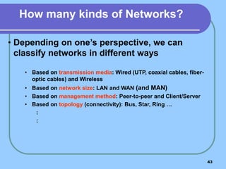
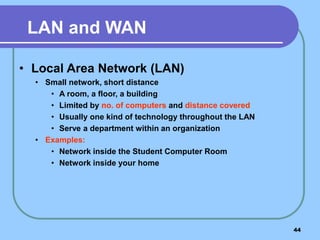
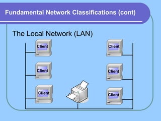
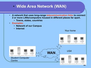
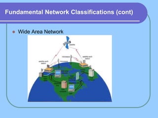
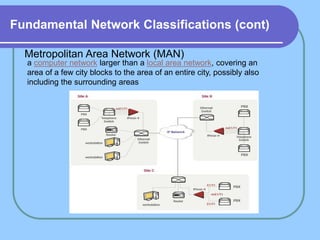
SlideShare a Scribd company logo
1 of 259
Computer Networks
Mona Ali
Course Objectives
1- Develop knowledge of key principles used for
data communication in computer networks.
2. Understand the evolution of networks and the
Internet.
3. Develop an understanding of the concepts and
issues involved in developing, designing and
implementing a computer network.
4. Develop skills in applying theoretical concepts in
the analysis of practical networking case studies.
Introduction to important concept principle
underling Communication in computer networks ,
key design issues, analysis and operation of
computer networks ,network design principles
,layering and protocols ,the OSI model and TCP/IP
model with particular attention given to the
physical ,data link ,network ,and transport layer
Lectures
1. History and overview.
2. Networks architectures and topologies.
3. Networks protocols.
4. Direct link networks.
5. Packet switching networks.
6. Internetworking: routing protocols and IP.
7. Global Internet and subnetting.
8. End-to-End protocols: TCP, UDP, and RTP.
10. Wireless and mobile networks.
11. Overview of Internet applications
5
History and overview
1.1 Growth of Computer Networking
Computer networking has grown explosively
Since the 1970s, computer communication has changed from a
research topic to an essential part of infrastructure
Networking is used in every aspect of our lives:
Business
Advertising
Production
Shipping
Planning
Billing
Accounting
1.1 Growth of Computer Networking
. Educational institutions are using computer
networks to provide students and teachers with
access to online information
. state, and local government offices use networks
1.1 Growth of Computer Networking
In short, computer networks are everywhere
In 1980, the Internet was a research project that involved a few
dozen sites
Today, the Internet has grown into a communication system
that reaches all of the world
Network has made telecommuting available to individuals
It has changed business communication
An entire industry emerged that develops networking
technologies, products, and services
Companies need workers to plan, install, operate, and
manage the hardware and software systems for networks
1.2 Why Networking Seems Complex
The networking subject seems complex, because
Many technologies exist
Each technology has features that distinguish it from the others
Companies create commercial network products and services
Computer networks seem complex
because technologies can be combined and interconnected
in many ways
Computer networks can be especially confusing to a beginner
because No single underlying theory exists that explains the
relationship among all parts
1.2 Why Networking Seems Complex
Multiple organizations have created computer networks
standards
some standards are incompatible with others
Various organizations have attempted to define conceptual
models
The set of technologies is diverse and changes rapidly
models are either so simplistic that they do not distinguish
among details or so complex that they do not help simplify
the subject
11
1.3 The Five Key Aspects of Networking
To master the complexity, it is important to gain a broad
background that includes five key aspects:
1.3.1 Network Applications and Network Programming
1.3.2 Data Communications
1.3.3 Packet Switching and Networking Technologies
1.3.4 Internetworking with TCP/IP
1.3.5 Additional Networking Concepts and Technologies
1.3.1 Network Applications and Network
Programming
Network services are provided by an application software
an application on one computer communicates across a
network with an application program running on another
computer
Network applications span a wide range, such as:
email
file transfer
web browsing
voice telephone calls (VoIP)
distributed databases
audio/video teleconferencing
Each application offers a specific service with its own form
of user interface
1.3.1 Network Applications and Network
Programming
it is possible to understand network applications, and even
possible to write code that communicates over a network,
without understanding the hardware/software technologies
However, knowledge of the underlying network system allows a
programmer to write better code and develop more efficient
applications
13
13
1.3.2 Data Communications
Data communications refers to the study of low-level
mechanisms and technologies used to send information
across a physical communication medium
such as a wire, radio wave, or light beam
Data communications focuses on ways to use physical
phenomena to transfer information
Data communications provides a foundation of concepts
on which the rest of networking is built
1.3.3 Packet Switching and Networking
Technologies
In 1960s, the packet switching concept revolutionized data
communications
Early communication networks had evolved from telegraph
and telephone systems
A physical pair of wires between two parties to form a
circuit
Packet switching changed networking in a fundamental way
It provided the basis for the modern Internet
Packet switching allows multiple users to share a network
Packet switching divides data into small blocks, called
packets
Devices throughout the network each have information
about how to reach each possible destination
1.3.3 Packet Switching and Networking
Technologies
 Many designs for packet switching are possible
 But there is a need for answers to basic questions:
 How should a destination be identified?
 How can a sender find the identification of a destination?
 How large should a packet be?
 How can a network recognize the end of one packet?
 How can a network recognize the beginning of another
packet?
 How can packet switching be adapted to wireless
networks?
1.3.3 Packet Switching and Networking
Technologies
 How can network technologies be designed to meet
various requirements for speed, distance, and economic
cost?
 Many packet switching technologies have been created
 to meet various requirements for speed, distance, and
economic cost
1.3.4 Internetworking with TCP/IP
In the 1970s, another revolution in computer networks arose:
Internet
In 1973, Vinton Cerf and Robert Kahn observed that
no single packet switching technology would ever satisfy all needs
especially because it would be possible to build low-capacity technologies
for homes or offices at extremely low cost
They suggested to stop trying to find a single best solution
Instead, explore interconnecting many packet switching
technologies into a functioning whole
They proposed a set of standards be developed for such an
interconnection
The resulting standards became known as the TCP/IP Internet
Protocol Suite (usually abbreviated TCP/IP)
1.4 Public and Private Parts of the Internet
The Internet consists of parts that are owned and operated by
individuals or organizations
From ownership point of view, we can categorize networks
1.4.1 Public Networks
1.4.2 Private Networks
A public network is run as a service that is available to subscribers
Any individual or corporation who pays the subscription fee can
use
A company that offers service is known as a service provider
Public refers to the general availability of service, not to the data
being transferred
A private network is controlled by one particular group
network use is restricted to one group
a private network can include circuits leased from a provider
1.4.2 Private Network
 Network vendors generally divide private networks into
four categories based on the size:
 Consumer
 Small Office / Home Office (SOHO)
 Small-to-Medium Business (SMB)
 Large Enterprise
 These categories are related to sales and market
1.5 Networks, Interoperability, and Standards
Communication always involves at least two entities
one that sends information and another that receives it
All entities in a network must agree on how information will be
represented and communicated
Communication agreements involve many details
the way that electrical signals are used to represent data
procedures used to initiate and conduct communication,
and the format of messages
An important issue is interoperability
it refers to the ability of two entities to communicate
All communicating parties agree on details and follow the same set of
rules, an exact set of specifications
Communication protocol, network protocol, or simply protocol to refer
to a specification for network communication
1.6 Protocol Suites and Layering Models
A set of protocols must be constructed
to ensure that the resulting communication system is
complete and efficient
Each protocol should handle a part of communication not
handled by other protocols
How can we guarantee that protocols work well together?
Instead of creating each protocol in isolation, protocols are
designed in complete, cooperative sets called suites or
families
Each protocol in a suite handles one aspect of networking
The protocols in a suite cover all aspects of communication
The entire suite is designed to allow the protocols to work
together efficiently
1.6 Protocol Suites and Layering Models
The fundamental abstraction used to collect protocols into a
unified whole is known as a layering model
All aspects of a communication problem can be partitioned into
pieces that work together
each piece is known as a layer
Dividing protocols into layers helps both protocol designers
and implementers manage the complexity
to concentrate on one aspect of communication at a given
time
Figure 1.1 illustrates the concept
by showing the layering model used with the Internet
protocols
24
1.6 Protocol Suites and Layering Models
 Physical Layer (Layer 1)
 specify details about the underlying transmission medium and
hardware
 all specifications related to electrical properties, radio
frequencies, and signals belong in layer 1
 Network Interface Layer (Layer 2)
 some publications use the term Data Link
 specify details about communication between higher layers of
protocols (implemented in SW) and the underlying network
(implemented in hardware)
 specifications about
 network addresses
 maximum packet size that a network can support
 protocols used to access the underlying medium
 and hardware addressing
1.6 Protocol Suites and Layering Models
 Internet Layer (Layer 3)
 Protocols in the Internet layer form the fundamental basis for
the Internet
 Layer 3 protocols specify communication across the Internet
(spanning multiple interconnected networks)
 Transport Layer (Layer 4)
 Provide for communication from an application program on one
computer to an application program on another
 Includes specifications on
 controlling the maximum rate a receiver can accept data
 mechanisms to avoid network congestion
 techniques to insure that all data is received in the correct
order
1.6 Protocol Suites and Layering Models
 Application Layer (Layer 5)
 specify how a pair of applications interact when they
communicate
 specify details about
 the format and
 the meaning of messages that applications can exchange
 the procedures to be followed
 Some examples of network applications in layer 5
 email exchange
 file transfer
 web browsing
 telephone services
 and video teleconferencing
28
1.7 How Data Passes Through Layers
Protocol implementations follow the layering model
by passing the output from a protocol in one layer to the input of a
protocol in the next
To achieve efficiency
rather than copy an entire packet
a pair of protocols in adjacent layers pass a pointer to the packet
Figure 1.2 illustrates layered protocols on the two computers
Each computer contains a set of layered protocols
When an application sends data
it is placed in a packet, and the packet passes down through
each layer of protocols
1.7 How Data Passes Through Layers
Once it has passed through all layers of protocols on the sending
computer
the packet leaves the computer and is transmitted across the
physical network
When it reaches the receiving computer
the packet passes up through the layers of protocols
If the application on the receiver sends a response, the process is
reversed
1.7 How Data Passes Through Layers
31
1.8 Headers and Layers
Each layer of protocol software performs computations
that insure the messages arrive as expected
To perform such computation, protocol software on the two
machines must exchange information
each layer on the sender prepends extra information onto the
packet
the corresponding protocol layer on the receiver removes and
uses the extra information
Additional information added by a protocol is known as a
header
Headers are added by protocol software on the sending
computer
That is, the Transport layer prepends a header, and then the
Internet layer prepends a header, and so on
1.8 Headers and Layers
If we observe a packet traversing the network, the
headers will appear in the order that Figure 1.3 illustrates
Although the figure shows headers as the same size
in practice headers are not of uniform size
and a physical layer header is optional
1.9 ISO and the OSI Seven-Layer Reference
Model
 At the same time the Internet protocols were being developed, two large
standards bodies jointly formed an alternative reference model
 They also created a set of internetworking protocols
 These organizations are:
 International Standardization Organization (ISO)
 International Telecommunications Union,Telecommunication (ITU-T)
 The ITU was known as the Consultative Committee for International
Telephone and Telegraph (CCITT)
 The ISO layering model is known as the Open Systems Interconnection
(OSI) Seven-Layer Reference Model
 Figure 1.4 illustrates the seven layers in the model
1.9 ISO and the OSI Seven-Layer Reference Model
35
1.10 The Inside Scoop
 ISO and the ITU use a process that accommodates as many viewpoints as
possible when creating a standard
 As a result, some standards can appear to have been designed by a
committee making political compromises rather than by engineers and
scientists
 The seven-layer reference model is controversial
 It did indeed start as a political compromise
 the model and the OSI protocols were designed as competitors for
the Internet protocols
 ISO and the ITU are huge standards bodies that handle the world-wide
telephone system and other global standards
 The Internet protocols and reference model were created by a small group
of about a dozen researchers
 It is easy to see why the standards organizations might be confident
that they could dictate a set of protocols and everyone would switch
away from protocols designed by researchers
 At one point, even the U.S. government was convinced that TCP/IP
should be replaced by OSI protocols
1.10 The Inside Scoop
 Eventually, it became clear that TCP/IP technology was technically
superior to OSI
 and efforts to develop and deploy OSI protocols were
terminated
 Standards bodies were left with the seven-layer model
 Advocates for the seven-layer model have tried to stretch the
definitions to match TCP/IP
 They argue that layer three could be considered an Internet layer
and that a few support protocols might be placed into layers five
and six
 Perhaps the most humorous part of the story is that many
engineers still refer to applications as layer 7 protocols
 even when they know that layers five and six are unfilled and
unnecessary
Introduction to computer networking
Networks architectures and topologies
Definitions
1.1 Network Definition
 A network can be defined as two or more
computers connected together in such a way
that they can share resources.
 The purpose of a network is to share
resources.
Definitions (cont..)
A resource may be:
 A file
 A folder
 A printer
 A disk drive
 Or just about anything else that exists on
a computer.
Definitions (cont..)
A network is simply a collection of computers or
other hardware devices that are connected
together, either physically or logically, using
special hardware and software, to allow them to
exchange information and cooperate. Networking
is the term that describes the processes involved
in designing, implementing, upgrading, managing
and otherwise working with networks and network
technologies.
Advantages of networking
 Connectivity and Communication
 Data Sharing
 Hardware Sharing
 Internet Access
 Internet Access Sharing
 Data Security and Management
 Performance Enhancement and Balancing
 Entertainment
The Disadvantages (Costs) of Networking
 Network Hardware, Software and Setup
Costs
 Hardware and Software Management and
Administration Costs
 Undesirable Sharing
 Illegal or Undesirable Behavior
 Data Security Concerns
43
• Depending on one’s perspective, we can
classify networks in different ways
• Based on transmission media: Wired (UTP, coaxial cables, fiber-
optic cables) and Wireless
• Based on network size: LAN and WAN (and MAN)
• Based on management method: Peer-to-peer and Client/Server
• Based on topology (connectivity): Bus, Star, Ring …
:
:
How many kinds of Networks?
44
LAN and WAN
• Local Area Network (LAN)
• Small network, short distance
• A room, a floor, a building
• Limited by no. of computers and distance covered
• Usually one kind of technology throughout the LAN
• Serve a department within an organization
• Examples:
• Network inside the Student Computer Room
• Network inside your home
Fundamental Network Classifications (cont)
The Local Network (LAN)
Client
Client
Client
Client Client
Client
46
• A network that uses long-range telecommunication links to connect
2 or more LANs/computers housed in different places far apart.
• Towns, states, countries
• Examples:
• Network of our Campus
• Internet
WAN
Student Computer
Centre
Your home
USA
• Wide Area Network (WAN)
Fundamental Network Classifications (cont)
 Wide Area Network
Fundamental Network Classifications (cont)
Metropolitan Area Network (MAN)
a computer network larger than a local area network, covering an
area of a few city blocks to the area of an entire city, possibly also
including the surrounding areas
Intranet and Internet Specifications
 Intranet: An intranet is a private network that is contained within
an enterprise. It may consist of many interlinked local area
networks and also use leased lines in the wide area network.
 An intranet uses TCP/IP, HTTP, and other Internet protocols and
in general looks like a private version of the Internet.
 Internet: is a worldwide system of computer networks - a network
of networks in which users at any one computer can, if they have
permission, get information from any other computer (and
sometimes talk directly to users at other computers).
Client and Server computer role in
networking
 Server computer is a core component of the network,
providing a link to the resources necessary to perform
any task.
 A server computer provides a link to the resources
necessary to perform any task.
 The link it provides could be to a resource existing on
the server itself or a resource on a client computer.
 Client computers normally request and receive
information over the network client. Client computers
also depends primarily on the central server for
processing activities
Peer-to peer network
 A peer-to-peer network is a network where the
computers act as both workstations and servers.
 great for small, simple, and inexpensive networks.
 In a strict peer-to-peer networking setup, every
computer is an equal, a peer in the network.
 Each machine can have resources that are shared
with any other machine.
 There is no assigned role for any particular device,
and each of the devices usually runs similar software.
Any device can and will send requests to any other.
Peer-to peer network (cont..)
53
• Advantages of peer-to-peer networks:
• Low cost
• Simple to configure
• User has full accessibility of the computer
• Disadvantages of peer-to-peer networks:
• May have duplication in resources
• Difficult to uphold security policy
• Difficult to handle uneven loading
• Where peer-to-peer network is appropriate:
• 10 or less users
• No specialized services required
• Security is not an issue
• Only limited growth in the foreseeable future
Client/Server Networking
 In this design, a small number of
computers are designated as centralized
servers and given the task of providing
services to a larger number of user
machines called clients
Client/Server Networking (cont..)
56
• Advantages of client/server networks
• Facilitate resource sharing – centrally administrate and control
• Facilitate system backup and improve fault tolerance
• Enhance security – only administrator can have access to Server
• Support more users
• Disadvantages of client/server networks
• High cost for Servers
• Need expert to configure the network
• Introduce a single point of failure to the system
Network topology
 A topology is a way of “laying out” the
network. Topologies can be either
physical or logical.
 Physical topologies describe how the
cables are run.
 Logical topologies describe how the
network messages travel
Network topology (cont.)
 Bus (can be both logical and physical)
 Star (physical only)
 Ring (can be both logical and physical)
 Mesh (can be both logical and physical)
Network topology (cont.)
Bus
 A bus is the simplest physical topology. It consists of a
single cable that runs to every workstation
 This topology uses the least amount of cabling, but
also covers the shortest amount of distance.
 Each computer shares the same data and address
path. With a logical bus topology, messages pass
through the trunk, and each workstation checks to see
if the message is addressed to itself. If the address of
the message matches the workstation’s address, the
network adapter copies the message to the card’s on-
board memory.
Network topology (cont.)
 it is difficult to add a workstation
 have to completely reroute the cable and
possibly run two additional lengths of it.
 if any one of the cables breaks, the
entire network is disrupted. Therefore, it
is very expensive to maintain.
Network topology (cont.)
 Bus topology
Network topology (cont.)
Star Topology
 A physical star topology branches each network
device off a central device called a hub, making it very
easy to add a new workstation.
 Also, if any workstation goes down it does not affect
the entire network. (But, as you might expect, if the
central device goes down, the entire network goes
down.)
 Some types of Ethernet use a physical star topology.
Figure 8.7 gives an example of the organization of the
star network.
Network topology (cont.)
 Star topologies are easy to install. A
cable is run from each workstation to the
hub. The hub is placed in a central
location in the office.
 Star topologies are more expensive to
install than bus networks, because there
are several more cables that need to be
installed, plus the cost of the hubs that
are needed.
Network topology (cont.)
 Star Topology
Network topology (cont.)
Ring
 Each computer connects to two other
computers, joining them in a circle creating a
unidirectional path where messages move
workstation to workstation.
 Each entity participating in the ring reads a
message, then regenerates it and hands it to
its neighbor on a different network cable.
Network topology (cont.)
 The ring makes it difficult to add new
computers.
 Unlike a star topology network, the ring
topology network will go down if one
entity is removed from the ring.
 Physical ring topology systems don’t
exist much anymore, mainly because the
hardware involved was fairly expensive
and the fault tolerance was very low.
Network topology (cont.)
 Ring Topology
Network topology (cont.)
Mesh
 The mesh topology is the simplest logical topology in terms of
data flow, but it is the most complex in terms of physical design.
 In this physical topology, each device is connected to every other
device
 This topology is rarely found in LANs, mainly because of the
complexity of the cabling.
 If there are x computers, there will be (x × (x–1)) ÷ 2 cables in the
network. For example, if you have five computers in a mesh
network, it will use 5 × (5 – 1) ÷ 2, which equals 10 cables. This
complexity is compounded when you add another workstation.
 For example, your five-computer, 10-cable network will jump to
15 cables just by adding one more computer.
Network topology (cont.)
 Because of its design, the physical mesh topology is very
expensive to install and maintain.
 Cables must be run from each device to every other device. The
advantage you gain from it is its high fault tolerance.
 With a logical mesh topology, however, there will always be a
way of getting the data from source to destination.
 It may not be able to take the direct route, but it can take an
alternate, indirect route. It is for this reason that the mesh
topology is still found in WANs to connect multiple sites across
WAN links. It uses devices called routers to search multiple
routes through the mesh and determine the best path.
 However, the mesh topology does become inefficient with five or
more entities.
Network topology (cont.)
 Mesh Topology
Network topology (cont.)
Advantages and Disadvantages of Network Topologies
Topology Advantages Disadvantages
Bus Cheap. Easy to install. Difficult to reconfigure.
Break in bus disables
entire network.
Star Cheap. Easy to install.
Easy to reconfigure.
Fault tolerant.
More expensive than bus.
Ring Efficient. Easy to install. Reconfiguration difficult.
Very expensive.
Mesh Simplest. Most fault tolerant. Reconfiguration extremely difficult.
Extremely expensive.
Very complex.
Hardware, Software and Networks
Peripherals (device)
 Network Interface Card (NIC)
 Repeater
 Hub
 Bridge
 Routers
 Switch
Hardware, Software and Networks Peripherals (cont.)
Network Interface Card (NIC)
 NIC provides the physical interface between computer and
cabling.
 It prepares data, sends data, and controls the flow of data. It can
also receive and translate data into bytes for the CPU to
understand.
 The following factors should be taken into consideration when
choosing a NIC:
1. - Preparing data
2. - Sending and controlling data
3. - Configuration
4. - Drivers
5. - Compatibility
6. - Performance
Hardware, Software and Networks Peripherals (cont.)
Preparing Data
 In the computer, data moves along buses in parallel,
as on a four-lane interstate highway. But on a network
cable, data travels in a single stream, as on a one lane
highway. This difference can cause problems
transmitting and receiving data, because the paths
traveled are not the same.
 It is the NIC’s job to translate the data from the
computer into signals that can flow easily along the
cable.
 It does this by translating digital signals into electrical
signals (and in the case of fiber-optic NICs, to optical
signals).
Hardware, Software and Networks Peripherals (cont.)
Sending and Controlling Data
 For two computers to send and receive data, the cards must
agree on several things. These include the following:
- The maximum size of the data frames
- The amount of data sent before giving
confirmation
- The time needed between transmissions
- The amount of time needed to wait before sending
confirmation
- The amount of data a card can hold
- The speed at which data transmits
 In order to successfully send data on the network, you need to
make sure the network cards are of the same type and they are
connected to the same piece of cable.
Hardware, Software and Networks Peripherals (cont.)
Configuration
 Each card must have a unique hardware
address. If two cards have the same hardware
addresses, neither one of them will be able to
communicate.
 For the computer to use the network interface
card, it is very important to install the proper
device drivers
Hardware, Software and Networks Peripherals (cont.)
Compatibility
 When choosing a NIC, use one that fits
the bus type of your PC. If you have
more than one type of bus in your PC
(for example, a combination ISA/PCI),
use an NIC that fits into the fastest type
(the PCI, in this case).
 This is especially important in servers, as
the NIC can very quickly become a
bottleneck if this guideline isn’t followed.
NIC card
Hardware, Software and Networks Peripherals (cont.)
Repeaters
 Repeaters are very simple devices. They allow a cabling system
to extend beyond its maximum allowed length by amplifying the
network voltages so they travel farther.
 Repeaters are nothing more than amplifiers and, as such, are
very inexpensive.
 Repeaters can only be used to regenerate signals between
similar network segments.
 For example, we can extend an Ethernet 10Base2 network to 400
meters with a repeater. But can’t connect an Ethernet and Token
Ring network together with one.
 The main disadvantage to repeaters is that they just amplify
signals. These signals not only include the network signals, but
any noise on the wire as well.
Hardware, Software and Networks Peripherals (cont.)
Repeaters
Hardware, Software and Networks Peripherals (cont.)
Hubs
 Hubs are devices used to link several computers
together.
 They repeat any signal that comes in on one port
and copy it to the other ports (a process that is
also called broadcasting).
 There are two types of hubs: active and passive.
 Passive hubs simply connect all ports together
electrically .
 Active hubs use electronics to amplify and clean
up the signal before it is broadcast to the other
ports.
 In the category of active hubs, there is also a class
called “intelligent” hubs, which are hubs that can
be remotely managed on the network.
Hardware, Software and Networks Peripherals (cont.)
Hubs
Hardware, Software and Networks Peripherals (cont.)
Bridges
 They join similar topologies and are used to divide network
segments.
 If it is aware of the destination address, it is able to forward
packets; otherwise a bridge will forward the packets to all
segments. They are more intelligent than repeaters but are
unable to move data across multiple networks
simultaneously.
 Unlike repeaters, bridges can filter out noise.
 The main disadvantage to bridges is that they can’t connect
dissimilar network types or perform intelligent path
selection. For that function, you would need a router.
Hardware, Software and Networks Peripherals (cont.)
Bridges
Hardware, Software and Networks Peripherals (cont.)
Routers
 Routers are highly intelligent devices that connect multiple
network types and determine the best path for sending data.
 The advantage of using a router over a bridge is that routers can
determine the best path that data can take to get to its
destination.
 Like bridges, they can segment large networks and can filter out
noise.
 However, they are slower than bridges because they are more
intelligent devices; as such, they analyze every packet, causing
packet-forwarding delays. Because of this intelligence, they are
also more expensive.
 Routers are normally used to connect one LAN to another.
 Typically, when a WAN is set up, there will be at least two routers
used.
Hardware, Software and Networks Peripherals (cont.)
Routers
Hardware, Software and Networks Peripherals (cont.)
Switch
 A network switch is a computer networking device that connects network
segments.
 Low-end network switches appear nearly identical to network hubs, but a switch
contains more "intelligence" .
 Network switches are capable of inspecting data packets as they are received,
determining the source and destination device of that packet, and forwarding it
appropriately.
 By delivering each message only to the connected device it was intended for, a
network switch conserves network bandwidth and offers generally better
performance than a hub.
 A vital difference between a hub and a switch is that all the nodes connected to
a hub share the bandwidth among themselves, while a device connected to a
switch port has the full bandwidth all to itself.
 For example, if 10 nodes are communicating using a hub on a 10-Mbps network,
then each node may only get a portion of the 10 Mbps if other nodes on the hub
want to communicate as well. .
 But with a switch, each node could possibly communicate at the full 10 Mbps.
Hardware, Software and Networks Peripherals (cont.)
Switch
89
Two main categories:
 Guided ― wires, cables
 Unguided ― wireless transmission, e.g. radio,
microwave, infrared, sound .
We will concentrate on guided media here:
 Twisted-Pair cables:
 Unshielded Twisted-Pair (UTP) cables
 Shielded Twisted-Pair (STP) cables
 Coaxial cables
 Fiber-optic cables
Transmission Media
 If the pair of wires are not twisted, electromagnetic
noises from, e.g., motors, will affect the closer wire more
than the further one, thereby causing errors
Twisted-Pair Cables
91
 Typically wrapped inside a plastic cover (for mechanical
protection)
 A sample UTP cable with 5 unshielded twisted pairs of wires
Metal
Insulato
r
Unshielded Twisted-Pair (UTP)
92
 STP cables are similar to UTP cables, except there
is a metal foil or braided-metal-mesh cover that
encases each pair of insulated wires
Shielded Twisted-Pair (STP)
93
EIA(Electronic Industries Alliance) classifies UTP cables
according to the quality:
 Category 1 ― the lowest quality, only good for voice,
mainly found in very old buildings, not recommended now
 Category 2 ― good for voice and low data rates (up to
4Mbps for low-speed token ring networks)
 Category 3 ― at least 3 twists per foot, for up to 10 Mbps
(common in phone networks in residential buildings)
 Category 4 ― up to 16 Mbps (mainly for token rings)
 Category 5 (or 5e) ― up to 100 Mbps (common for
networks targeted for high-speed data communications)
 Category 6 ― more twists than Cat 5, up to 1 Gbps
Categories of UTP Cables
94
 In general, coaxial cables, or coax, carry signals of
higher freq (100KHz–500MHz) than UTP cables
 Outer metallic wrapping serves both as a shield
against noise and as the second conductor that
completes the circuit
Coaxial Cables
95
 Light travels at 3108 ms-1 in free space and is the
fastest possible speed in the Universe
 Light slows down in denser media, e.g. glass
 Refraction occurs at interface, with light bending away
from the normal when it enters a less dense medium
 Beyond the critical angle  total internal reflection
Fiber-Optic Cables
96
 An optical fiber consists of a core (denser material)
and a cladding (less dense material)
 Simplest one is a multimode step-index optical fiber
 Multimode = multiple paths, whereas step-index =
refractive index follows a step-function profile (i.e.
an abrupt change of refractive index between the
core and the cladding)
 Light bounces back and forth along
the core
 Common light sources: LEDs and
lasers
Fiber Construction
Guided Media – Fiber-Optic Cable
Fiber-optic Cable Connectors
Guided Media – Fiber-Optic Cable
100
 Noise resistance ― external light is blocked by outer jacket
 Less signal attenuation ― a signal can run for miles
without regeneration (currently, the lowest measured loss
is about ~4% or 0.16dB per km)
 Higher bandwidth ― currently, limits on data rates come
from the signal generation/reception technology, not the
fiber itself
 Cost ― Optical fibers are expensive
 Installation/maintenance ― any crack in the core will
degrade the signal, and all connections must be perfectly
aligned
Advantages and Disadvantages
Comparison of Physical Media
Wireless transmission waves
Unguided Media
Broadcast Radio
 Radio is a general term used to encompass frequencies
 radio is 3kHz to 300GHz
 use broadcast radio, 30MHz - 1GHz, for:
 FM radio
 UHF (Ultra_high_frequency) and
 VHF (very-high_frequency television
 is Omnidirectional
 suffers from multipath interference
 reflections from land, water, other objects
Omnidirectional Antenna
Unguided Media – Radio Waves
 Frequencies between 3 KHz and
1 GHz.
 are used for multicasts
communications, such as radio and
television, and ...
Terrestrial Microwave
 used for long haul telecommunications
 and short point-to-point links
 requires fewer repeaters but line of sight
 use a parabolic dish to focus a narrow beam
onto a receiver antenna
 1-40GHz frequencies
 higher frequencies give higher data rates
 main source of loss is distance, rainfall
also interference
 Frequencies between 1 and 300 GHz.
 Used for unicast communication such as cellular phones, satellite
networks and wireless LANs.
Unguided Media – Microwaves
Unidirectional Antenna
Satellite Microwave
 satellite is relay station
 receives on one frequency, amplifies or repeats
signal and transmits on another frequency
 eg. uplink 5.925-6.425 GHz & downlink 3.7-4.2 GHz
 typically requires geo-stationary orbit
 height of 35,784km
 typical uses
 television
 long distance telephone
 private business networks
 global positioning
Unguided Media – Infrared
 Frequencies between 300 GHz to 400 THz.
 Can not penetrate walls.
Used for short-range communication in a
closed area using line-of-sight propagation.
Infrared
 end line of sight (or reflection)
 are blocked by walls
 no licenses required
 typical uses
 TV remote control
Antennas
 electrical conductor used to radiate or collect
electromagnetic energy
 transmission antenna
 radio frequency energy from transmitter
 converted to electromagnetic energy by antenna
 radiated into surrounding environment
 reception antenna
 electromagnetic energy impinging on antenna
 converted to radio frequency electrical energy
 fed to receiver
 same antenna is often used for both purposes
Radiation Pattern
 power radiated in all directions
 not same performance in all directions
 as seen in a radiation pattern diagram
 radiates in all directions equally
 measure of directionality of antenna
 measured in decibels (dB)
Satellite Point to Point Link
Satellite Broadcast Link
Wireless Propagation
Ground Wave
Wireless Propagation
Sky Wave
Wireless Propagation
Line of Sight
Refraction
 velocity of electromagnetic wave is a function
of density of material
~3 x 10⁸ m/s in vacuum, less in anything else
 speed changes as move between media
 varies with wavelength
Line of Sight Transmission
 Free space loss
 loss of signal with distance
 Atmospheric Absorption
 from water vapour and oxygen absorption
 Multipath
 multiple interfering signals from reflections
 Refraction
 bending signal away from receiver
Multipath Interference
Comparison of Media
 Medium Cost Speed Atten Interfere Security
 UTP Low 1-100M High High Low
 STP Medium 1-150M High Medium Low
 Coax Medium 1M–1G Medium Medium Low
 Fibre High 10M–2G Low Low High
 Radio Medium 1-10M Varies High Low
 Microwv High 1M–10G Varies High Medium
 Satellite High 1 M–10G Varies High Medium
 Cellular High 9.6–19.2K Low Medium Low
122
Network Protocols
123
Function of Packets in Network
Communications
 Networks reformat data into smaller,
more manageable pieces called packets
or frames
 Advantages of splitting data include:
 More efficient transmission, since large
units of data saturate network
 More computers able to use network
 Faster transmissions since only packets
containing errors need to be retransmitted
124
Packet Structure
 Three basic parts of packet, as seen in
Figure 1:
 Header – contains source and destination
address along with clocking information to
synchronize transmission
 Data – payload or actual data can vary from
512 bytes to 16 kilobytes
 Trailer – information to verify packet’s
contents, such as Cyclic Redundancy
Check (CRC)
125
Typical Packet Structure
126
Packet Creation
 From sender, data moves down layers of
OSI model
 Each layer adds header or trailer
information
 Data travels up layers at receiver
 Each layer removes header or trailer
information placed by corresponding sender
layer
 See Figure 2
127
Header/Trailer Information Added or
Removed
128
Packet Creation (continued)
 Outgoing data stream enters OSI model
as complete message
 Remains as data at layers 5-7
 Lower layers split data
 Transport layer 4 splits it into segments
 Network layer 3 splits segments into
packets
 Data Link layer 2 puts packets into frames
 Physical layer 1 transmits packets as bits
The different between the segment
,frame,paket
 A Ethernet "Frame" is the layer 2 frame that is given to the nic card for
transmission.
An IP "Packet" is the information starting with the IP header, and includes all
upper layer protocol information.
And, a TCP segment, encapsulates all higher level protocols above it.
129
130
Understanding Packets
 Three kinds of packets:
 Unicast packet – addressed to only one
computer
 Broadcast packet – created for all
computers
on network
 Multicast packet – created for any
computers on network that “listen” to shared
network address
131
Protocols
 Rules and procedures for communicating
 To communicate, computers must agree
on protocols
 Many kinds of protocols:
 Connectionless
 Connection-oriented
 Routable
 No routable
132
The Function of Protocols
 Each protocol has different purpose and
function
 Protocols may work at one or more layers
 More sophisticated protocols operate at higher
layers of OSI model
 Protocol stack or protocol suite is set of
protocols that work cooperatively
 Most common protocol stack is TCP/IP used
by the Internet and pretty much all operating
systems
133
Protocols in a Layered
Architecture
 Most protocols can be positioned and
explained in terms of layers of OSI model
 Protocol stacks may have different protocols
for each layer
 See Figure 3 for review of functions of each
layer of OSI model
 See Figure 4 for three major protocol types
 Application protocols at layers 5-7
 Transport protocols at layer 4
 Network protocols at layers 1-3
134
Functions of OSI Model Layers
135
Three Main Protocol Types
136
Network Protocols
 Provide addressing and routing information, error
checking, and retransmission requests
 Services provided by network protocols are called link
services
 Popular network protocols include:
 Internet Protocol version 4 (IPv4)
 Internetwork Packet Exchange (IPX) and NWLink
 NetBEUI
 Internet Protocol version 6 (IPv6)
137
Transport Protocols
 Handle data delivery between computers
 May be connectionless or connection-
oriented
 Transport protocols include:
 Transmission Control Protocol (TCP)
 Sequenced Packet Exchange (SPX) and
NWLink
 NetBIOS/NetBEUI
138
Application Protocols
 Operate at upper layers of OSI model to
provide application-to-application service
 Some common application protocols are:
 Simple Mail Transport Protocol (SMTP)
 File Transfer Protocol (FTP)
 Simple Network Management Protocol
(SNMP)
 NetWare Core Protocol (NCP)
 AppleTalk File Protocol (AFP)
139
Transmission Control Protocol/ Internet Protocol (TCP/IP)
 Called the Internet Protocol (IP)
 Most commonly used protocol suite for networking
 Able to connect different types of computers and
networks
 Default protocol for Novell NetWare, Windows
XP/2000/2003, all Unix/Linux varieties, and Mac OS X
 See Figure 6-5 for relationship to OSI model
140
TCP/IP Compared to OSI Model
141
IP Addressing
 Logical addresses, 32-bits or 4 bytes long
 Four octets separated by periods, each with
decimal value from 0-255
 First part of address identifies network
 Second part of address identifies host or
individual computer
 IP addresses broken into classes
 Number of IP address registries under control
of Internet Assigned Numbers Authority
(IANA)
142
Classless Inter-Domain Routing (CIDR)
 Internet uses CIDR
 Demarcation between network and host not always
based on octet boundaries
 May be based on specific number of bits from beginning
of address
 Called subnetting, the process involves “stealing” bits
from host portion of address
for use in network address
 Provides fewer hosts on each network but
more networks overall
143
Subnet Masks
 Part of IP address identifies network and
part identifies host
 IP uses subnet mask to determine what
part
of address identifies network and what
part identifies host
 Network section identified by binary 1
 Host section identified by binary 0
144
Network Address Translation
(NAT)
 Allows organization to use private IP
addresses while connected to the
Internet
 Performed by network device such as
router that connects to Internet
 See Simulation 6-3 and Figure 6-6 for
examples of NAT
145
Network Address Translation (NAT) (continued)
146
Dynamic Host Configuration Protocol
(DHCP)
 DHCP server receives block of available
IP addresses and their subnet masks
 When computer needs address, DHCP
server selects one from pool of available
addresses
 Can move computers with ease; no need
to reconfigure IP addresses
 Some systems, such as Web servers,
must have static IP address
147
IPv6
 Current four byte version is IPv4
 Now reaching limit of 4-byte addresses
 IPv6 being used now on the Internet
backbone and other large networks
 Uses 16 byte (128-bit) addresses
 Retains backward compatibility with IPv4
4-byte addresses
 Will provide limitless supply of addresses
148
NetBIOS and NetBEUI
 Consortium of Microsoft, 3Com, and IBM
developed lower-level protocol NetBEUI
in mid-1980s
 NetBIOS Extended User Interface
 Spans layers 2, 3, and 4 of OSI model
 Both designed for small- to medium-
sized networks, from 2-250 computers
149
NetBIOS and NetBEUI (continued)
 Figure 6-7 shows Microsoft protocol suite and its
relationship to OSI model
 Defines four components above Data Link layer
 Runs on any network card or physical medium
 Redirector interprets requests and determines
whether they are local or remote
 If remote, passes request to Server Message
Block (SMB)
 SMB passes information between networked
computers
150
Microsoft Protocol Suite Compared to OSI Model
151
NetBIOS and NetBEUI (continued)
 NetBEUI works at Transport layer to
manage communications between two
computers
 Non routable protocol; skips Network layer
 NetBEUI packet does not contain source or
destination network information
152
NetBIOS and NetBEUI (continued)
 NetBIOS operates at Session layer to provide peer-to-
peer network application support
 Unique 15-character name identifies each
computer in NetBIOS network
 NetBIOS broadcast advertises computer’s name
 Connection-oriented protocol, but can also use
connectionless communications
 Non routable protocol, but can be routed when
using routable protocol for transport
153
NetBIOS and NetBEUI (continued)
 NetBEUI is small, fast, nonroutable Transport and Data
Link protocol
 All Windows versions include it
 Ideal for DOS based computers
 Good for slow serial links
 Limited to small networks
 Server Message Block operates at Presentation layer
 Used to communicate between redirector and server
software
154
IPX/SPX(Internetwork Packet/Sequenced Packet
Exchange
 Original protocol suite designed for Novell’s NetWare
network operating system
 Still supported with NetWare 6.0, but TCP/IP
is now primary protocol
 NWLink is Microsoft’s implementation of IPX/SPX
protocol suite
 Figure 6-8 shows protocols in NWLink and
corresponding OSI layers
 Must consider which Ethernet frame type with
NWLink
155
NWLink Compared to OSI Model
156
AppleTalk
 Defines physical transport in Apple
Macintosh networks
 Divides computers in zones
 AppleTalk Phase II allows connectivity
outside Macintosh world
157
Implementing and Removing
Protocols
 Easy to add or remove protocols
 TCP/IP loads automatically when most
operating systems are installed
 In Windows 2000/2003/XP, use Local
Area Connections Properties to add or
remove protocols
 See Figure 6-9
158
Network and Dial-up
Connections
159
Putting Data on the Cable:
Access Methods
 Consider several factors
 How computers put data on the cable
 How computers ensure data reaches
destination undamaged
160
Function of Access Methods
 Rules specify when computers can
access cable or data channel
 Channel access methods assure data
reaches its destination
 Prevents two or more computers from
sending messages that may collide on cable
 Allows only one computer at a time to send
data
161
Major Access Methods
 Channel access is handled at Media
Access Control (MAC) sublayer of Data
Link layer
 Five major access methods:
 Contention
 Switching
 Token passing
 Demand priority
 Polling
162
Contention
 In early networks, contention method allowed
computers to send data whenever they had data to
send, resulting in frequent collisions and
retransmissions
 Figure 6-11 shows data collision
 Two carrier access methods were developed for
contention-based networks
 Carrier Sense Multiple Access with
Collision Detection (CSMA/CD)
 Carrier Sense Multiple Access with
Collision Avoidance (CSMA/CA)
163
Data Collision
164
CSMA/CD
 Popular access method used by
Ethernet
 Prevents collisions by listening to channel
 If no data on line, may send message
 If collision occurs, stations wait random
period of time before resending data
 See Figure 6-11
165
CSMA/CD (continued)
166
CSMA/CD (continued)
 Limitations and disadvantages of
CSMA/CD:
 Not effective at distances over 2500 meters
 More computers on network likely to cause
more collisions
 Computers have unequal access to media
 Computer with large amount of data can
monopolize channel
167
CSMA/CA
 Uses collision avoidance, rather than
detection, to avoid collisions
 When computer senses channel is free, it
signals its intent to transmit data
 Used with Apple’s LocalTalk
 Advantages and disadvantages:
 More reliable than CSMA/CD at avoiding
collisions
 “Intent to transmit” packets add overhead
and reduce network speed
168
Switching
 Switch interconnects individual nodes and controls
access to media
 Switching usually avoids contention and allows
connections to use entire bandwidth
 Other advantages include:
 Fairer than contention-based technology
 Permits multiple simultaneous conversations
 Supports centralized management
 Disadvantage include:
 Higher cost
 Failure of switch brings down network
169
Token Passing
 Token passes sequentially from one computer to next
 Only computer with token can send data, as
seen in Figure 6-12
 Advantages and disadvantages:
 Prevents collisions
 Provides all computers equal access to
media
 Computer must wait for token to transmit,
even if no other computer wants to transmit
 Complicated process requires more
expensive equipment
170
Communication in a
Token-Passing Network
171
Demand Priority
 Used only by 100VG-AnyLAN 100 Mbps
 100BaseVG is a 100 Mbit/s Ethernet standard specified
to run over four pairs of category 3 UTP wires (known as
voice grade, hence the "VG"). It is also called 100VG-
AnyLANbecause it was defined to carry both Ethernet
and token ring frame types.
 Ethernet standard (IEEE 802.12)
 Runs on star bus topology, as seen in Figure 6-13
 Intelligent hubs control access to network
 Computer sends hub demand signal when it wants to
transmit
 Advantages and disadvantages:
 Allows certain computers to have higher
priorities
 Eliminates extraneous traffic by not
broadcasting packets but sending them to
each computer
 Price is major disadvantage
172
173
Demand Priority Uses
Star Bus Topology
174
Polling
 One of oldest access methods
 Central controller, called primary device, asks each
computer or secondary device if it has data to send, as
seen in Figure 6-14
 Advantages and disadvantages:
 Allows all computers equal access to channel
 Can grant priority for some computers
 Does not make efficient use of media
 If primary device fails, network fails
175
Primary Device Controls Polling
176
Choosing an Access Method
 Network topology is biggest factor in
choosing access method
 Ring topology usually uses token-passing
 Switching can emulate all common
topologies
177
Chapter Summary
 Data stream on a network is divided into packets to provide
more reliable data delivery and ease network traffic
 If errors occur during transmission, only packets with errors
will be re-sent
 As data travels through layers of OSI model, each layer adds
its own header or trailer information to packet
 As receiving computer processes packet, each layer strips its
header or trailer information and properly re-sequences
segmented message so that packet is in original form
 Many protocols are available for network communications
178
Chapter Summary (continued)
 Each protocol has strengths and weaknesses
 A suite, or stack, of protocols allows a number of
protocols to work cooperatively
 Major protocol suites are TCP/IP, IPX/SPX, and
NetBEUI
 Each suite contains many smaller protocols, each of
which has its own network function
179
Chapter Summary (continued)
 Current method for Internet addressing is called CIDR,
which uses all available addresses more efficiently
 IPv6 will eventually replace IPv4
 When a computer is ready to send data, it must be
assured that data will reach destination
 Perfect environment does not exist where all computers
can have dedicated channel over which to send
information
 Rules have been established to ensure that all
computers have time on the channel
180
Chapter Summary (continued)
 Demand priority allows computer to send
data after it notifies controlling hub
 Switching can emulate all other access
methods and offers greatest total available
bandwidth
Introduction to TCP/IP
History and Future of TCP/IP
 The U.S. Department of
Defense (DoD) created the
TCP/IP reference model
because it wanted a
network that could survive
any conditions.
 Some of the layers in the
TCP/IP model have the
same name as layers in the
OSI model.
Application Layer
 Handles high-level protocols, issues of
representation, encoding, and dialog
control.
 The TCP/IP protocol suite combines all
application related issues into one layer
and ensures this data is properly
packaged before passing it on to the
next layer.
Application Layer Examples
Transport Layer
Five basic services:
 Segmenting upper-layer application data
 Establishing end-to-end operations
 Sending segments from one end host to
another end host
 Ensuring data reliability
 Providing flow control
Transport Layer Protocols
Internet Layer
The internet layer is a group of internetworking methods,
protocols, and specifications in the Internet protocol
suite that are used to transport datagrams (packets) from
the originating host across network boundaries, if
necessary, to the destination host specified by a network
address (IP address) which is defined for this purpose by
the Internet Protocol (IP).
Internet Layer
Network Access Layer
 The network access layer is concerned with all of the issues
that an IP packet requires to actually make a physical link to
the network media.
 It includes the LAN and WAN technology details, and all the
details contained in the OSI physical and data link layers.
Comparing the OSI Model and TCP/IP
Model
Similarities of the OSI and TCP/IP
Models
 Both have layers.
 Both have application layers, though they
include very different services.
 Both have comparable transport and
network layers.
 Packet-switched, not circuit-switched,
technology is assumed.
 Networking professionals need to know
both models.
Differences of the OSI and TCP/IP
Models
 TCP/IP combines the presentation and session
layer into its application layer.
 TCP/IP combines the OSI data link and physical
layers into one layer.
 TCP/IP appears simpler because it has fewer
layers.
 TCP/IP transport layer using UDP does not
always guarantee reliable delivery of packets as
the transport layer in the OSI model does.
The TCP Connection
 TCP provides multiplexing, demultiplexing,
and error detection. (but not recovery) in
exactly the same manner as UDP
Nevertheless, TCP and UDP differ in many
ways. The most fundamental difference is that
UDP is connectionless, while TCP is
connection-oriented. UDP is
connectionless
 because it sends data without ever
establishing a connection.
 TCP is connection-oriented because before one
application process can begin to send
data to another, the two processes must first "handshake"
with each other -- that is, they must send some
preliminary segments to each other to
establish the parameters of the ensuing data transfer. As
part of the TCP connection establishment, both sides of
the connection will initialize many TCP "state variables
Three handshake in TCP
A TCP connection provides for full duplex data
transfer. That is, application-level data can
be transferred in both directions between
two hosts – if there is a TCP connection
between process A on one host and process B
on another host, then application-level data can
flow from A to B at the same
time as application-level data flows from B to A.
Let us now take a look at how a TCP connection is
established. Suppose a process running in one host
wants to initiate a connection with another
process in another host. Recall that the host that is
initiating the connection is called the client host, while
the other host is called the server host. The
client application process first informs the client TCP that it
wants to establish a connection to a process in the
server.
Internet Addresses
IP Addressing
 An IP address is a 32-bit sequence of 1s and 0s.
 To make the IP address easier to use, the
address is usually written as four decimal
numbers separated by periods.
 This way of writing the address is called the
dotted decimal format.
Decimal and Binary Conversion
IPv4 Addressing
Class A, B, C, D, and E IP Addresses
Reserved IP Addresses
 Certain host addresses are
reserved and cannot be
assigned to devices on a
network.
 An IP address that has
binary 0s in all host bit
positions is reserved for the
network address.
 An IP address that has
binary 1s in all host bit
positions is reserved for the
network address.
Public and Private IP Addresses
 No two machines that connect to a public network can
have the same IP address because public IP addresses
are global and standardized.
 However, private networks that are not connected to the
Internet may use any host addresses, as long as each
host within the private network is unique.
 RFC (Request for Comments )1918 sets aside three
blocks of IP addresses for private, internal use.
 Connecting a network using private addresses to the
Internet requires translation of the private addresses to
public addresses using Network Address Translation
(NAT).
IPv4 versus IPv6
 IP version 6 (IPv6) has
been defined and
developed.
 IPv6 uses 128 bits
rather than the 32 bits
currently used in IPv4.
 IPv6 uses hexadecimal
numbers to represent
the 128 bits.
IPv4
Obtaining an IP Address
Obtaining an Internet Address
 Static addressing
 Each individual device must be configured with
an IP address.
 Dynamic addressing
 Reverse Address Resolution Protocol (RARP)
 Bootstrap Protocol (BOOTP)
 Dynamic Host Configuration Protocol (DHCP)
 DHCP initialization sequence
 Function of the Address Resolution Protocol
 ARP operation within a subnet
Static Assignment of IP Addresses
 Each individual
device must be
configured with an
IP address.
Reverse Address Resolution Protocol (RARP)
MAC HEADER IP HEADER
RARP REQUEST
MESSAGE
Destination
FF-FF-FF-FF-FF-FF
Source
FE:ED:FD:23:44:EF
Destination
255.255.255.255
Source
????????
What is my IP
address?
BOOTP IP
 The Bootstrap Protocol (BOOTP)
operates in a client/server environment
and only requires a single packet
exchange to obtain IP information.
 BOOTP packets can include the IP
address, as well as the address of a
router, the address of a server, and
vendor-specific information.
Dynamic Host Configuration Protocol
 Allows a host to obtain an IP address
using a defined range of IP addresses on
a DHCP server.
 As hosts come online, contact the DHCP
server, and request an address.
Problems in Address Resolution
 In TCP/IP communications, a datagram on a local-
area network must contain both a destination MAC
address and a destination IP address.
 There needs to be a way to automatically map IP
to MAC addresses.
 The TCP/IP suite has a protocol, called Address
Resolution Protocol (ARP), which can
automatically obtain MAC addresses for local
transmission.
 TCP/IP has a variation on ARP called Proxy ARP
that will provide the MAC address of an
intermediate device for transmission outside the
LAN to another network segment.
Address Resolution Protocol (ARP)
 Each device on a network maintains its
own ARP table.
 A device that requires an IP and MAC
address pair broadcasts an ARP
request.
 If one of the local devices matches the
IP address of the request, it sends back
an ARP reply that contains its IP-MAC
pair.
 If the request is for a different IP
network, a router performs a proxy ARP.
 The router sends an ARP response with
the MAC address of the interface on
which the request was received, to the
requesting host.
Introduction to Subnetting
 As the Internet grew
 the original classful addressing scheme
became a limitation
 Everyone demanded a class A or class B
address
 So they would have enough addresses for
future growth
 but many addresses in class A and B were unused
 Many class C addresses remained, but few
wanted to use them
Introduction to Subnetting
 Two mechanisms were invented to overcome the
limitation:
 Subnet addressing
 Classless addressing
 The two mechanisms are closely related
 Subnet addressing was initially used within large
organizations.
 Classless addressing extended the approach to all
Internet.
216
Subnet and Classless Addressing
 Assume an ISP owns a class C prefix
 Classful addressing assigns the entire prefix to one
organization
 With classless addressing
 the ISP can divide the prefix into several longer
prefixesand assign each to a subscriber
 Figure 21.4 illustrates how classless addressing allows
an ISP to divide a class C prefix into four (4) longer
prefixes each one can accommodate a network of up to
62 hosts
 The original class C address has 8 bits
of suffix and each of the classless
addresses has 6 bits of suffix
 Thus, instead of wasting addresses
 ISP can assign each of the four (4)
classless prefixes to a subscriber
218
Subnet and Classless Addressing
219
Address Masks
 How can an IP address be divided at an arbitrary boundary?
 The classless and subnet addressing schemes require
hosts and routers to store an additional piece of information:
a value that specifies the exact boundary between the
network prefix and the host suffix
 To mark the boundary, IP uses a 32-bit value
 known as an address mask, also called a subnet mask
Address Masks
 Why store the boundary size as a bit mask?
 A mask makes processing efficient
 Hosts and routers need to compare the network prefix
portion of the address to a value in their forwarding
tables.
 The bit-mask representation makes the comparison
efficient
221
Address Masks
 Suppose a router is given
 a destination address, D
 a network prefix represented as a 32-bit value, N
 a 32-bit address mask, M
 Assume the top bits of N contain a network prefix, and the
remaining bits have been set to zero
 To test whether the destination lies on the specified
network, the router tests the condition:
N == (D & M)
222
Address Masks( As an example)
:
 Consider the following 32-bit network prefix:
10000000 00001010 00000000 00000000 = 128.10.0.0
 Consider a 32-bit mask:
11111111 11111111 00000000 00000000 = 255.255.0.0
 Consider a 32-bit destination address, which has a
10000000 00001010 00000010 00000011 = 128.10.2.3
223
CIDR Notation
 Classless Inter-Domain Routing (CIDR)
 The name is unfortunate because CIDR only specifies addressing
and forwarding
 Designers wanted to make it easy for a human to specify a mask
 Consider the mask needed for the example in Figure 21.4b
 It has 26 bits of 1s followed by 6 bits of 0s
 The general form of CIDR notation is: ddd.ddd.ddd.ddd/m
 ddd is the decimal value for an octet of the address
 m is the number of one bits in the mask
 Thus, one might write the following: 192.5.48.69/26
 which specifies a mask of 26 bits
 Figure 21.5 lists address masks in CIDR notation
 along with the dotted decimal equivalent of each
224
Figure 21.5
A list of address
masks in CIDR
notation and in
dotted decimal
225
A CIDR Example
 Assume an ISP has the following block 128.211.0.0/16
 Suppose the ISP has 2 customers
 one customer needs 12 IP addresses and the other needs 9
 The ISP can assign
 customer1 CIDR: 128.211.0.16/28
 customer2 CIDR: 128.211.0.32/28
 both customers have the same mask size (28 bits), the prefixes differ
 The binary value assigned to customer1 is:
10000000 11010011 00000000 0001 0000
 The binary value assigned to customer2 is:
10000000 11010011 00000000 0010 0000
 There is no ambiguity
 Each customer has a unique prefix
Example of special address
 1-Directed Broadcast Address
 2- Limited Broadcast Address
 3- This Computer Address
 4- Loopback Address
227
Special IP Addresses
Directed Broadcast Address
To simplify broadcasting (send to all)
 IP defines a directed broadcast address for each physical network
 When a packet is sent to a network's directed broadcast
 a single copy of the packet travels across the Internet
 until it reaches the specified network
 the packet is then delivered to all hosts on the network
 The directed broadcast address for a network is formed by adding a
suffix that consists of all 1 bits to the network prefix
228
Special IP Addresses
Limited Broadcast Address

 Limited broadcast refers to a broadcast on a directly-
connected network:
 informally, we say that the broadcast is limited to a
“single wire”
 Limited broadcast is used during system startup
 by a computer that does not yet know the network
number
 IP reserves the address consisting of 32-bits of 1s
 refer to limited broadcast
 Thus, IP will broadcast any packet sent to the all-1s address
across the local network
229
Special IP Addresses
This Computer Address
 A computer needs to know its IP address
 before it can send or receive Internet packets
 TCP/IP contains protocols a computer can use to obtain its
IP address automatically when the computer boots
 The startup protocols also use an IP to communicate
 When using such startup protocols
 a computer cannot supply a correct IP source address
 To handle such cases
 IP reserves the address that consists of all 0s to mean
this computer
230
Special IP Addresses
Loopback Address

 Loopback address used to test network applications
 It is used for preliminary debugging after a network application has been
created
 A programmer must have two application programs that are intended to
communicate across a network
 Each application includes the code needed to interact with TCP/IP
 Instead of executing each program on a separate computer
 the programmer runs both programs on a single computer
 and instructs them to use a loopback address when communicating
 When one application sends data to another
 data travels down the protocol stack to the IP software
 then forwards it back up through the protocol stack to the second
program
231
Special IP Addresses
Loopback Address
 A programmer can test the program logic quickly
 without needing two computers and without sending
packets across a network
 IP reserves the network prefix 127/8 for use with loopback
232
Summary of Special IP Addresses
 The table in Figure 21.7 summarizes the special IP addresses
233
Internet Routing
and
Routing Protocols
234
Static Vs. Dynamic Routing
 IP routing can be partitioned into two broad categories:
 Static routing
 Dynamic routing
 Static routing forwarding table is created before the system starts to
forward packets
 and does not change entries, unless manually altering them
 In dynamic routing route propagation software runs on the system and
continuously updates the forwarding table
 to insure that each datagram follows an optimum route
 the software communicates with other systems to learn optimum
routes to each destination
 it continually checks for network failures that cause routes to change
 dynamic routing begins exactly like static routing
 by loading an initial set of routes into a forwarding table when the
system boots
235
Static Routing in Hosts
and a Default Route
 Static routing is straightforward and easy to specify
 It does not require extra routing software
 It does not consume bandwidth
 and no CPU cycles are required to propagate routing information
 However, static routing is relatively inflexible
 it cannot accommodate network failures or changes in topology
 Where is static routing used?
 Most hosts use static routing
 especially in cases where the host has one network connection and
a single router connects the network to the rest of the Internet
 Cosider the architecture in Figure 27.1
236
Static Routing in Hosts
and a Default Route
237
Dynamic Routing and Routers
 Can a router in the Internet use static routing the same way a host
does?
 Most routers use dynamic routing
 but in some exceptional cases static routing can be used
 As an exception
(case where static routing does suffice for a router)
238
Dynamic Routing and Routers
 Each router exchanges information with other routers
 When it learns about changes in routes
 the routing software updates the local forwarding table
 Routers exchange information periodically
 the local forwarding table is updated continuously
 In Figure 27.2 routers R1 and R2 will exchange routing information
 As a result, routing software in R2 will install a route to network 1 and
software running in R1 will install a route to network 2
 If router R2 crashes, the route propagation software in R1 will detect
that network 2 is no longer reachable
 and will remove the route from its forwarding table
 Later, when R2 comes back on line, the routing software in R1 will
determine that network 2 is reachable again
 and will reinstall the route
239
Packet-Switching Networks
240
Circuit Switching (e.g., Phone Network)
 Source establishes connection to destination
 Node along the path store connection info
 Nodes may reserve resources for the
connection
 Source sends data over the connection
 No destination address, since nodes know path
241
Circuit Switching With Human Operator
242
Circuit Switching: Multiplexing a Link
 Time-division
 Each circuit
allocated certain
time slots
 Frequency-division
 Each circuit
allocated certain
frequencies
time
frequency
time
243
Advantages of Circuit Switching
 Guaranteed bandwidth
 Predictable communication performance
 Simple abstraction
 Reliable communication channel between hosts
 No worries about lost or out-of-order packets
 Simple forwarding
 Forwarding based on time slot or frequency
 No need to inspect a packet header
 Low per-packet overhead
 Forwarding based on time slot or frequency
 No IP (and TCP/UDP) header on each packet
244
Disadvantages of Circuit Switching
 Wasted bandwidth
 Bursty traffic leads to idle connection during silent
period
 Unable to achieve gains from statistical multiplexing
 Blocked connections
 Connection refused when resources are not
sufficient
 Unable to offer “okay” service to everybody
Disadvantages of Circuit Switching
 Connection set-up delay
 No communication until the connection is set up
 Network state
 Network nodes must store per-connection
information
246
Packet Switching (e.g., Internet)
 Data traffic divided into packets
 Each packet contains a header (with address)
 Packets travel separately through network
 Packet forwarding based on the header
 Network nodes may store packets temporarily
 Destination reconstructs the message
247
Packet Switching: Statistical Multiplexing
Packets
248
IP Service: Best-Effort Packet Delivery
 Packet switching
 Divide messages into a sequence of packets
 Headers with source and destination address
 Best-effort delivery
 Packets may be lost
 Packets may be corrupted
 Packets may be delivered out of order
source destination
IP network
249
IP Service Model: Why Packets?
 Don’t want to waste bandwidth
 No traffic exchanged during idle periods
 Better to allow multiplexing
 Different transfers share access to same links
 Packets can be delivered by most anything
 … still, packet switching can be inefficient
 Extra header bits on every packet
250
IP Service Model: Why Best-Effort?
 IP means never having to say you’re sorry…
 Don’t need to reserve bandwidth and memory
 Don’t need to do error detection & correction
 Don’t need to remember from one packet to next
 … but, applications do want efficient, accurate transfer
of data in order, in a timely fashion
251
IP Service: Best-Effort is Enough
 No error detection or correction
 Higher-level protocol can provide error checking
 Successive packets may not follow the same path
 Not a problem as long as packets reach the
destination
 Packets can be delivered out-of-order
 Receiver can put packets back in order (if
necessary)
 Packets may be lost or arbitrarily delayed
 Sender can send the packets again (if desired)
IP Packet Structure
4-bit
Version
4-bit
Header
Length
8-bit
Type of Service
(TOS)
16-bit Total Length (Bytes)
16-bit Identification
3-bit
Flags 13-bit Fragment Offset
8-bit Time to
Live (TTL)
8-bit Protocol 16-bit Header Checksum
32-bit Source IP Address
32-bit Destination IP Address
Options (if any)
Payload
253
IP Header: Version, Length, ToS
 Version number (4 bits)
 Indicates the version of the IP protocol
 Necessary to know what other fields to expect
 Typically “4” (for IPv4), and sometimes “6” (for IPv6)
 Header length (4 bits)
 Number of 32-bit words in the header
 Type-of-Service (8 bits)
 Allow packets to be treated differently based on needs
 E.g., low delay for audio, high bandwidth for bulk transfer
254
IP Header: Length, Fragments, TTL
 Total length (16 bits)
 Number of bytes in the packet
 Maximum size is 63,535 bytes (216 -1)
 Fragmentation information (32 bits)
 Packet identifier, flags, and fragment offset
 Supports dividing a large IP packet into fragments
 … in case a link cannot handle a large IP packet
 Time-To-Live (8 bits)
 Used to identify packets stuck in forwarding loops
 … and eventually discard them from the network
255
IP Header: More on Time-to-Live (TTL)
 Potential problem
 Forwarding loops can cause packets to cycle
forever
 Confusing if the packet arrives much later
 Time-to-live field in packet header
 TTL field decremented by each router on the path
 Packet is discarded when TTL field reaches 0…
 …and “time exceeded” message is sent to the
source
256
IP Header: Use of TTL in Traceroute
 Time-To-Live field in IP packet header
 Source sends a packet with a TTL of n
 Each router along the path decrements the TTL
 “TTL exceeded” sent when TTL reaches 0
 Trace route tool exploits this TTL behavior
source
destination
TTL=1
Time
exceeded
TTL=2
Send packets with TTL=1, 2, … and record source of “time exceeded” message
257
IP Header Fields: Transport Protocol
 Protocol (8 bits)
 Identifies the higher-level protocol
 E.g., “6” for the Transmission Control Protocol (TCP)
 E.g., “17” for the User Datagram Protocol (UDP)
IP header IP header
TCP header UDP header
protocol=6
protocol=17
258
IP Header: Checksum on the Header
 Checksum (16 bits)
 Sum of all 16-bit words in the IP packet header
 If any bits of the header are corrupted in transit
 … the checksum won’t match at receiving host
 Receiving host discards corrupted packets
 Sending host will retransmit the packet, if needed
134
+ 212
= 346
134
+ 216
= 350
Mismatch!
259
IP Header: To and From Addresses
 Two IP addresses
 Source IP address (32 bits)
 Destination IP address (32 bits)
 Destination address
 Unique identifier for the receiving host
 Allows each node to make forwarding decisions
 Source address
 Unique identifier for the sending host
 Destination can decide whether to accept packet
 Enables Destination to send a reply back to
source

More Related Content

Similar to 1-introduction-to-computer-networking.ppt

Slides for protocol layering and network applications
Slides for protocol layering and network applicationsSlides for protocol layering and network applications
Slides for protocol layering and network applicationsjajinekkanti
 
Introduction to Computer Networking
Introduction to Computer NetworkingIntroduction to Computer Networking
Introduction to Computer Networkingshankars73
 
Unit 3 Assignment 1 Osi Model
Unit 3 Assignment 1 Osi ModelUnit 3 Assignment 1 Osi Model
Unit 3 Assignment 1 Osi ModelJacqueline Thomas
 
Comparison of DOD and OSI Model in the Internet Communication
Comparison of DOD and OSI Model in the Internet CommunicationComparison of DOD and OSI Model in the Internet Communication
Comparison of DOD and OSI Model in the Internet Communicationijtsrd
 
Introduction to Networks_v0.2
Introduction to Networks_v0.2Introduction to Networks_v0.2
Introduction to Networks_v0.2Sohail Gohir
 
Itmg360 chapter one_v05
Itmg360 chapter one_v05Itmg360 chapter one_v05
Itmg360 chapter one_v05Anuja Lad
 
BBA 3331, Introduction to E-commerce 1 Course Learnin.docx
 BBA 3331, Introduction to E-commerce 1 Course Learnin.docx BBA 3331, Introduction to E-commerce 1 Course Learnin.docx
BBA 3331, Introduction to E-commerce 1 Course Learnin.docxShiraPrater50
 
Computer networking class 12
Computer networking class 12Computer networking class 12
Computer networking class 12LakshyaT
 
Information technology .pptx
Information technology .pptxInformation technology .pptx
Information technology .pptxHizbaMemon
 
Networking And Telecommunications
Networking And TelecommunicationsNetworking And Telecommunications
Networking And TelecommunicationsUMaine
 
Security And Privacy Issues Of Iots
Security And Privacy Issues Of IotsSecurity And Privacy Issues Of Iots
Security And Privacy Issues Of IotsSamantha Randall
 
cn ppt.pptxbdbdbbxnxnxbxbxbxbxnxnxnxnxnxnxn
cn ppt.pptxbdbdbbxnxnxbxbxbxbxnxnxnxnxnxnxncn ppt.pptxbdbdbbxnxnxbxbxbxbxnxnxnxnxnxnxn
cn ppt.pptxbdbdbbxnxnxbxbxbxbxnxnxnxnxnxnxnBharathNS10
 
Untitled.pptxhsgdgshshshhdhdhdbxbxbxbxbxhx
Untitled.pptxhsgdgshshshhdhdhdbxbxbxbxbxhxUntitled.pptxhsgdgshshshhdhdhdbxbxbxbxbxhx
Untitled.pptxhsgdgshshshhdhdhdbxbxbxbxbxhxBharathNS10
 

Similar to 1-introduction-to-computer-networking.ppt (20)

Punit kumar
Punit kumarPunit kumar
Punit kumar
 
Slides for protocol layering and network applications
Slides for protocol layering and network applicationsSlides for protocol layering and network applications
Slides for protocol layering and network applications
 
Chapters1&2.pdf
Chapters1&2.pdfChapters1&2.pdf
Chapters1&2.pdf
 
Ie20303week1
Ie20303week1Ie20303week1
Ie20303week1
 
Introduction to Computer Networking
Introduction to Computer NetworkingIntroduction to Computer Networking
Introduction to Computer Networking
 
3.1 Network Basic
3.1 Network Basic3.1 Network Basic
3.1 Network Basic
 
Unit 3 Assignment 1 Osi Model
Unit 3 Assignment 1 Osi ModelUnit 3 Assignment 1 Osi Model
Unit 3 Assignment 1 Osi Model
 
Comparison of DOD and OSI Model in the Internet Communication
Comparison of DOD and OSI Model in the Internet CommunicationComparison of DOD and OSI Model in the Internet Communication
Comparison of DOD and OSI Model in the Internet Communication
 
Introduction to Networks_v0.2
Introduction to Networks_v0.2Introduction to Networks_v0.2
Introduction to Networks_v0.2
 
Itmg360 chapter one_v05
Itmg360 chapter one_v05Itmg360 chapter one_v05
Itmg360 chapter one_v05
 
K010426371
K010426371K010426371
K010426371
 
BBA 3331, Introduction to E-commerce 1 Course Learnin.docx
 BBA 3331, Introduction to E-commerce 1 Course Learnin.docx BBA 3331, Introduction to E-commerce 1 Course Learnin.docx
BBA 3331, Introduction to E-commerce 1 Course Learnin.docx
 
Computer networking class 12
Computer networking class 12Computer networking class 12
Computer networking class 12
 
Networks Basics
Networks BasicsNetworks Basics
Networks Basics
 
Information technology .pptx
Information technology .pptxInformation technology .pptx
Information technology .pptx
 
Networking And Telecommunications
Networking And TelecommunicationsNetworking And Telecommunications
Networking And Telecommunications
 
Security And Privacy Issues Of Iots
Security And Privacy Issues Of IotsSecurity And Privacy Issues Of Iots
Security And Privacy Issues Of Iots
 
cn ppt.pptxbdbdbbxnxnxbxbxbxbxnxnxnxnxnxnxn
cn ppt.pptxbdbdbbxnxnxbxbxbxbxnxnxnxnxnxnxncn ppt.pptxbdbdbbxnxnxbxbxbxbxnxnxnxnxnxnxn
cn ppt.pptxbdbdbbxnxnxbxbxbxbxnxnxnxnxnxnxn
 
Untitled.pptxhsgdgshshshhdhdhdbxbxbxbxbxhx
Untitled.pptxhsgdgshshshhdhdhdbxbxbxbxbxhxUntitled.pptxhsgdgshshshhdhdhdbxbxbxbxbxhx
Untitled.pptxhsgdgshshshhdhdhdbxbxbxbxbxhx
 
networking
networking networking
networking
 

More from MemMem25

‏‏chpater1Typing Arabic and English Ergonomics .pptx
‏‏chpater1Typing  Arabic and English Ergonomics .pptx‏‏chpater1Typing  Arabic and English Ergonomics .pptx
‏‏chpater1Typing Arabic and English Ergonomics .pptxMemMem25
 
‏‏chapter4 Technical Skills Hardware Skills - نسخة.ppt
‏‏chapter4  Technical Skills Hardware  Skills - نسخة.ppt‏‏chapter4  Technical Skills Hardware  Skills - نسخة.ppt
‏‏chapter4 Technical Skills Hardware Skills - نسخة.pptMemMem25
 
chapter3 Technical Skills Software Skills.ppt
chapter3  Technical Skills Software Skills.pptchapter3  Technical Skills Software Skills.ppt
chapter3 Technical Skills Software Skills.pptMemMem25
 
chapter2 Technical Support.ppt
chapter2 Technical Support.pptchapter2 Technical Support.ppt
chapter2 Technical Support.pptMemMem25
 
‏‏chapter1 overview of OFFICE MANAGEMENT - نسخة.ppt
‏‏chapter1  overview  of  OFFICE MANAGEMENT - نسخة.ppt‏‏chapter1  overview  of  OFFICE MANAGEMENT - نسخة.ppt
‏‏chapter1 overview of OFFICE MANAGEMENT - نسخة.pptMemMem25
 
‏‏chapter 4 Office Management Software.ppt
‏‏chapter 4  Office Management Software.ppt‏‏chapter 4  Office Management Software.ppt
‏‏chapter 4 Office Management Software.pptMemMem25
 
chapter3 Major Processes of Office Management.ppt
chapter3  Major Processes of Office Management.pptchapter3  Major Processes of Office Management.ppt
chapter3 Major Processes of Office Management.pptMemMem25
 
chapter 2 FUNCTIONS OF MODERN OFFICE.ppt
chapter 2  FUNCTIONS OF MODERN OFFICE.pptchapter 2  FUNCTIONS OF MODERN OFFICE.ppt
chapter 2 FUNCTIONS OF MODERN OFFICE.pptMemMem25
 
acd120_Organizational Behavior (2) (1) (1).pptx
acd120_Organizational Behavior (2) (1) (1).pptxacd120_Organizational Behavior (2) (1) (1).pptx
acd120_Organizational Behavior (2) (1) (1).pptxMemMem25
 
Chapter 3 .pptx
Chapter 3 .pptxChapter 3 .pptx
Chapter 3 .pptxMemMem25
 
NE223_chapter 1_Overview of operating systems.ppt
NE223_chapter 1_Overview of operating systems.pptNE223_chapter 1_Overview of operating systems.ppt
NE223_chapter 1_Overview of operating systems.pptMemMem25
 
Algorithm Analysis.pdf
Algorithm Analysis.pdfAlgorithm Analysis.pdf
Algorithm Analysis.pdfMemMem25
 
lec(1).pptx
lec(1).pptxlec(1).pptx
lec(1).pptxMemMem25
 
Chapter02.ppt
Chapter02.pptChapter02.ppt
Chapter02.pptMemMem25
 
desmath(1).ppt
desmath(1).pptdesmath(1).ppt
desmath(1).pptMemMem25
 
COE332-Ch03d.pptx
COE332-Ch03d.pptxCOE332-Ch03d.pptx
COE332-Ch03d.pptxMemMem25
 
01_Artificial_Intelligence-Introduction.ppt
01_Artificial_Intelligence-Introduction.ppt01_Artificial_Intelligence-Introduction.ppt
01_Artificial_Intelligence-Introduction.pptMemMem25
 

More from MemMem25 (19)

‏‏chpater1Typing Arabic and English Ergonomics .pptx
‏‏chpater1Typing  Arabic and English Ergonomics .pptx‏‏chpater1Typing  Arabic and English Ergonomics .pptx
‏‏chpater1Typing Arabic and English Ergonomics .pptx
 
‏‏chapter4 Technical Skills Hardware Skills - نسخة.ppt
‏‏chapter4  Technical Skills Hardware  Skills - نسخة.ppt‏‏chapter4  Technical Skills Hardware  Skills - نسخة.ppt
‏‏chapter4 Technical Skills Hardware Skills - نسخة.ppt
 
chapter3 Technical Skills Software Skills.ppt
chapter3  Technical Skills Software Skills.pptchapter3  Technical Skills Software Skills.ppt
chapter3 Technical Skills Software Skills.ppt
 
chapter2 Technical Support.ppt
chapter2 Technical Support.pptchapter2 Technical Support.ppt
chapter2 Technical Support.ppt
 
‏‏chapter1 overview of OFFICE MANAGEMENT - نسخة.ppt
‏‏chapter1  overview  of  OFFICE MANAGEMENT - نسخة.ppt‏‏chapter1  overview  of  OFFICE MANAGEMENT - نسخة.ppt
‏‏chapter1 overview of OFFICE MANAGEMENT - نسخة.ppt
 
‏‏chapter 4 Office Management Software.ppt
‏‏chapter 4  Office Management Software.ppt‏‏chapter 4  Office Management Software.ppt
‏‏chapter 4 Office Management Software.ppt
 
chapter3 Major Processes of Office Management.ppt
chapter3  Major Processes of Office Management.pptchapter3  Major Processes of Office Management.ppt
chapter3 Major Processes of Office Management.ppt
 
chapter 2 FUNCTIONS OF MODERN OFFICE.ppt
chapter 2  FUNCTIONS OF MODERN OFFICE.pptchapter 2  FUNCTIONS OF MODERN OFFICE.ppt
chapter 2 FUNCTIONS OF MODERN OFFICE.ppt
 
acd120_Organizational Behavior (2) (1) (1).pptx
acd120_Organizational Behavior (2) (1) (1).pptxacd120_Organizational Behavior (2) (1) (1).pptx
acd120_Organizational Behavior (2) (1) (1).pptx
 
Chapter 3 .pptx
Chapter 3 .pptxChapter 3 .pptx
Chapter 3 .pptx
 
NE223_chapter 1_Overview of operating systems.ppt
NE223_chapter 1_Overview of operating systems.pptNE223_chapter 1_Overview of operating systems.ppt
NE223_chapter 1_Overview of operating systems.ppt
 
Algorithm Analysis.pdf
Algorithm Analysis.pdfAlgorithm Analysis.pdf
Algorithm Analysis.pdf
 
lec(1).pptx
lec(1).pptxlec(1).pptx
lec(1).pptx
 
AI.ppt
AI.pptAI.ppt
AI.ppt
 
Chapter02.ppt
Chapter02.pptChapter02.ppt
Chapter02.ppt
 
desmath(1).ppt
desmath(1).pptdesmath(1).ppt
desmath(1).ppt
 
COE332-Ch03d.pptx
COE332-Ch03d.pptxCOE332-Ch03d.pptx
COE332-Ch03d.pptx
 
LAB1.pptx
LAB1.pptxLAB1.pptx
LAB1.pptx
 
01_Artificial_Intelligence-Introduction.ppt
01_Artificial_Intelligence-Introduction.ppt01_Artificial_Intelligence-Introduction.ppt
01_Artificial_Intelligence-Introduction.ppt
 

Recently uploaded

REMIFENTANIL: An Ultra short acting opioid.pptx
REMIFENTANIL: An Ultra short acting opioid.pptxREMIFENTANIL: An Ultra short acting opioid.pptx
REMIFENTANIL: An Ultra short acting opioid.pptxDr. Ravikiran H M Gowda
 
Understanding Accommodations and Modifications
Understanding  Accommodations and ModificationsUnderstanding  Accommodations and Modifications
Understanding Accommodations and ModificationsMJDuyan
 
dusjagr & nano talk on open tools for agriculture research and learning
dusjagr & nano talk on open tools for agriculture research and learningdusjagr & nano talk on open tools for agriculture research and learning
dusjagr & nano talk on open tools for agriculture research and learningMarc Dusseiller Dusjagr
 
On National Teacher Day, meet the 2024-25 Kenan Fellows
On National Teacher Day, meet the 2024-25 Kenan FellowsOn National Teacher Day, meet the 2024-25 Kenan Fellows
On National Teacher Day, meet the 2024-25 Kenan FellowsMebane Rash
 
UGC NET Paper 1 Unit 7 DATA INTERPRETATION.pdf
UGC NET Paper 1 Unit 7 DATA INTERPRETATION.pdfUGC NET Paper 1 Unit 7 DATA INTERPRETATION.pdf
UGC NET Paper 1 Unit 7 DATA INTERPRETATION.pdfNirmal Dwivedi
 
PANDITA RAMABAI- Indian political thought GENDER.pptx
PANDITA RAMABAI- Indian political thought GENDER.pptxPANDITA RAMABAI- Indian political thought GENDER.pptx
PANDITA RAMABAI- Indian political thought GENDER.pptxakanksha16arora
 
FSB Advising Checklist - Orientation 2024
FSB Advising Checklist - Orientation 2024FSB Advising Checklist - Orientation 2024
FSB Advising Checklist - Orientation 2024Elizabeth Walsh
 
Sensory_Experience_and_Emotional_Resonance_in_Gabriel_Okaras_The_Piano_and_Th...
Sensory_Experience_and_Emotional_Resonance_in_Gabriel_Okaras_The_Piano_and_Th...Sensory_Experience_and_Emotional_Resonance_in_Gabriel_Okaras_The_Piano_and_Th...
Sensory_Experience_and_Emotional_Resonance_in_Gabriel_Okaras_The_Piano_and_Th...Pooja Bhuva
 
Economic Importance Of Fungi In Food Additives
Economic Importance Of Fungi In Food AdditivesEconomic Importance Of Fungi In Food Additives
Economic Importance Of Fungi In Food AdditivesSHIVANANDaRV
 
How to Manage Global Discount in Odoo 17 POS
How to Manage Global Discount in Odoo 17 POSHow to Manage Global Discount in Odoo 17 POS
How to Manage Global Discount in Odoo 17 POSCeline George
 
HMCS Vancouver Pre-Deployment Brief - May 2024 (Web Version).pptx
HMCS Vancouver Pre-Deployment Brief - May 2024 (Web Version).pptxHMCS Vancouver Pre-Deployment Brief - May 2024 (Web Version).pptx
HMCS Vancouver Pre-Deployment Brief - May 2024 (Web Version).pptxmarlenawright1
 
Simple, Complex, and Compound Sentences Exercises.pdf
Simple, Complex, and Compound Sentences Exercises.pdfSimple, Complex, and Compound Sentences Exercises.pdf
Simple, Complex, and Compound Sentences Exercises.pdfstareducators107
 
NO1 Top Black Magic Specialist In Lahore Black magic In Pakistan Kala Ilam Ex...
NO1 Top Black Magic Specialist In Lahore Black magic In Pakistan Kala Ilam Ex...NO1 Top Black Magic Specialist In Lahore Black magic In Pakistan Kala Ilam Ex...
NO1 Top Black Magic Specialist In Lahore Black magic In Pakistan Kala Ilam Ex...Amil baba
 
Towards a code of practice for AI in AT.pptx
Towards a code of practice for AI in AT.pptxTowards a code of practice for AI in AT.pptx
Towards a code of practice for AI in AT.pptxJisc
 
Exploring_the_Narrative_Style_of_Amitav_Ghoshs_Gun_Island.pptx
Exploring_the_Narrative_Style_of_Amitav_Ghoshs_Gun_Island.pptxExploring_the_Narrative_Style_of_Amitav_Ghoshs_Gun_Island.pptx
Exploring_the_Narrative_Style_of_Amitav_Ghoshs_Gun_Island.pptxPooja Bhuva
 
Beyond_Borders_Understanding_Anime_and_Manga_Fandom_A_Comprehensive_Audience_...
Beyond_Borders_Understanding_Anime_and_Manga_Fandom_A_Comprehensive_Audience_...Beyond_Borders_Understanding_Anime_and_Manga_Fandom_A_Comprehensive_Audience_...
Beyond_Borders_Understanding_Anime_and_Manga_Fandom_A_Comprehensive_Audience_...Pooja Bhuva
 
How to setup Pycharm environment for Odoo 17.pptx
How to setup Pycharm environment for Odoo 17.pptxHow to setup Pycharm environment for Odoo 17.pptx
How to setup Pycharm environment for Odoo 17.pptxCeline George
 
Introduction to TechSoup’s Digital Marketing Services and Use Cases
Introduction to TechSoup’s Digital Marketing  Services and Use CasesIntroduction to TechSoup’s Digital Marketing  Services and Use Cases
Introduction to TechSoup’s Digital Marketing Services and Use CasesTechSoup
 
Spellings Wk 4 and Wk 5 for Grade 4 at CAPS
Spellings Wk 4 and Wk 5 for Grade 4 at CAPSSpellings Wk 4 and Wk 5 for Grade 4 at CAPS
Spellings Wk 4 and Wk 5 for Grade 4 at CAPSAnaAcapella
 

Recently uploaded (20)

REMIFENTANIL: An Ultra short acting opioid.pptx
REMIFENTANIL: An Ultra short acting opioid.pptxREMIFENTANIL: An Ultra short acting opioid.pptx
REMIFENTANIL: An Ultra short acting opioid.pptx
 
VAMOS CUIDAR DO NOSSO PLANETA! .
VAMOS CUIDAR DO NOSSO PLANETA!                    .VAMOS CUIDAR DO NOSSO PLANETA!                    .
VAMOS CUIDAR DO NOSSO PLANETA! .
 
Understanding Accommodations and Modifications
Understanding  Accommodations and ModificationsUnderstanding  Accommodations and Modifications
Understanding Accommodations and Modifications
 
dusjagr & nano talk on open tools for agriculture research and learning
dusjagr & nano talk on open tools for agriculture research and learningdusjagr & nano talk on open tools for agriculture research and learning
dusjagr & nano talk on open tools for agriculture research and learning
 
On National Teacher Day, meet the 2024-25 Kenan Fellows
On National Teacher Day, meet the 2024-25 Kenan FellowsOn National Teacher Day, meet the 2024-25 Kenan Fellows
On National Teacher Day, meet the 2024-25 Kenan Fellows
 
UGC NET Paper 1 Unit 7 DATA INTERPRETATION.pdf
UGC NET Paper 1 Unit 7 DATA INTERPRETATION.pdfUGC NET Paper 1 Unit 7 DATA INTERPRETATION.pdf
UGC NET Paper 1 Unit 7 DATA INTERPRETATION.pdf
 
PANDITA RAMABAI- Indian political thought GENDER.pptx
PANDITA RAMABAI- Indian political thought GENDER.pptxPANDITA RAMABAI- Indian political thought GENDER.pptx
PANDITA RAMABAI- Indian political thought GENDER.pptx
 
FSB Advising Checklist - Orientation 2024
FSB Advising Checklist - Orientation 2024FSB Advising Checklist - Orientation 2024
FSB Advising Checklist - Orientation 2024
 
Sensory_Experience_and_Emotional_Resonance_in_Gabriel_Okaras_The_Piano_and_Th...
Sensory_Experience_and_Emotional_Resonance_in_Gabriel_Okaras_The_Piano_and_Th...Sensory_Experience_and_Emotional_Resonance_in_Gabriel_Okaras_The_Piano_and_Th...
Sensory_Experience_and_Emotional_Resonance_in_Gabriel_Okaras_The_Piano_and_Th...
 
Economic Importance Of Fungi In Food Additives
Economic Importance Of Fungi In Food AdditivesEconomic Importance Of Fungi In Food Additives
Economic Importance Of Fungi In Food Additives
 
How to Manage Global Discount in Odoo 17 POS
How to Manage Global Discount in Odoo 17 POSHow to Manage Global Discount in Odoo 17 POS
How to Manage Global Discount in Odoo 17 POS
 
HMCS Vancouver Pre-Deployment Brief - May 2024 (Web Version).pptx
HMCS Vancouver Pre-Deployment Brief - May 2024 (Web Version).pptxHMCS Vancouver Pre-Deployment Brief - May 2024 (Web Version).pptx
HMCS Vancouver Pre-Deployment Brief - May 2024 (Web Version).pptx
 
Simple, Complex, and Compound Sentences Exercises.pdf
Simple, Complex, and Compound Sentences Exercises.pdfSimple, Complex, and Compound Sentences Exercises.pdf
Simple, Complex, and Compound Sentences Exercises.pdf
 
NO1 Top Black Magic Specialist In Lahore Black magic In Pakistan Kala Ilam Ex...
NO1 Top Black Magic Specialist In Lahore Black magic In Pakistan Kala Ilam Ex...NO1 Top Black Magic Specialist In Lahore Black magic In Pakistan Kala Ilam Ex...
NO1 Top Black Magic Specialist In Lahore Black magic In Pakistan Kala Ilam Ex...
 
Towards a code of practice for AI in AT.pptx
Towards a code of practice for AI in AT.pptxTowards a code of practice for AI in AT.pptx
Towards a code of practice for AI in AT.pptx
 
Exploring_the_Narrative_Style_of_Amitav_Ghoshs_Gun_Island.pptx
Exploring_the_Narrative_Style_of_Amitav_Ghoshs_Gun_Island.pptxExploring_the_Narrative_Style_of_Amitav_Ghoshs_Gun_Island.pptx
Exploring_the_Narrative_Style_of_Amitav_Ghoshs_Gun_Island.pptx
 
Beyond_Borders_Understanding_Anime_and_Manga_Fandom_A_Comprehensive_Audience_...
Beyond_Borders_Understanding_Anime_and_Manga_Fandom_A_Comprehensive_Audience_...Beyond_Borders_Understanding_Anime_and_Manga_Fandom_A_Comprehensive_Audience_...
Beyond_Borders_Understanding_Anime_and_Manga_Fandom_A_Comprehensive_Audience_...
 
How to setup Pycharm environment for Odoo 17.pptx
How to setup Pycharm environment for Odoo 17.pptxHow to setup Pycharm environment for Odoo 17.pptx
How to setup Pycharm environment for Odoo 17.pptx
 
Introduction to TechSoup’s Digital Marketing Services and Use Cases
Introduction to TechSoup’s Digital Marketing  Services and Use CasesIntroduction to TechSoup’s Digital Marketing  Services and Use Cases
Introduction to TechSoup’s Digital Marketing Services and Use Cases
 
Spellings Wk 4 and Wk 5 for Grade 4 at CAPS
Spellings Wk 4 and Wk 5 for Grade 4 at CAPSSpellings Wk 4 and Wk 5 for Grade 4 at CAPS
Spellings Wk 4 and Wk 5 for Grade 4 at CAPS
 

1-introduction-to-computer-networking.ppt

  • 2. Course Objectives 1- Develop knowledge of key principles used for data communication in computer networks. 2. Understand the evolution of networks and the Internet. 3. Develop an understanding of the concepts and issues involved in developing, designing and implementing a computer network. 4. Develop skills in applying theoretical concepts in the analysis of practical networking case studies.
  • 3. Introduction to important concept principle underling Communication in computer networks , key design issues, analysis and operation of computer networks ,network design principles ,layering and protocols ,the OSI model and TCP/IP model with particular attention given to the physical ,data link ,network ,and transport layer
  • 4. Lectures 1. History and overview. 2. Networks architectures and topologies. 3. Networks protocols. 4. Direct link networks. 5. Packet switching networks. 6. Internetworking: routing protocols and IP. 7. Global Internet and subnetting. 8. End-to-End protocols: TCP, UDP, and RTP. 10. Wireless and mobile networks. 11. Overview of Internet applications
  • 6. 1.1 Growth of Computer Networking Computer networking has grown explosively Since the 1970s, computer communication has changed from a research topic to an essential part of infrastructure Networking is used in every aspect of our lives: Business Advertising Production Shipping Planning Billing Accounting
  • 7. 1.1 Growth of Computer Networking . Educational institutions are using computer networks to provide students and teachers with access to online information . state, and local government offices use networks
  • 8. 1.1 Growth of Computer Networking In short, computer networks are everywhere In 1980, the Internet was a research project that involved a few dozen sites Today, the Internet has grown into a communication system that reaches all of the world Network has made telecommuting available to individuals It has changed business communication An entire industry emerged that develops networking technologies, products, and services Companies need workers to plan, install, operate, and manage the hardware and software systems for networks
  • 9. 1.2 Why Networking Seems Complex The networking subject seems complex, because Many technologies exist Each technology has features that distinguish it from the others Companies create commercial network products and services Computer networks seem complex because technologies can be combined and interconnected in many ways Computer networks can be especially confusing to a beginner because No single underlying theory exists that explains the relationship among all parts
  • 10. 1.2 Why Networking Seems Complex Multiple organizations have created computer networks standards some standards are incompatible with others Various organizations have attempted to define conceptual models The set of technologies is diverse and changes rapidly models are either so simplistic that they do not distinguish among details or so complex that they do not help simplify the subject
  • 11. 11 1.3 The Five Key Aspects of Networking To master the complexity, it is important to gain a broad background that includes five key aspects: 1.3.1 Network Applications and Network Programming 1.3.2 Data Communications 1.3.3 Packet Switching and Networking Technologies 1.3.4 Internetworking with TCP/IP 1.3.5 Additional Networking Concepts and Technologies
  • 12. 1.3.1 Network Applications and Network Programming Network services are provided by an application software an application on one computer communicates across a network with an application program running on another computer Network applications span a wide range, such as: email file transfer web browsing voice telephone calls (VoIP) distributed databases audio/video teleconferencing Each application offers a specific service with its own form of user interface
  • 13. 1.3.1 Network Applications and Network Programming it is possible to understand network applications, and even possible to write code that communicates over a network, without understanding the hardware/software technologies However, knowledge of the underlying network system allows a programmer to write better code and develop more efficient applications 13 13
  • 14. 1.3.2 Data Communications Data communications refers to the study of low-level mechanisms and technologies used to send information across a physical communication medium such as a wire, radio wave, or light beam Data communications focuses on ways to use physical phenomena to transfer information Data communications provides a foundation of concepts on which the rest of networking is built
  • 15. 1.3.3 Packet Switching and Networking Technologies In 1960s, the packet switching concept revolutionized data communications Early communication networks had evolved from telegraph and telephone systems A physical pair of wires between two parties to form a circuit Packet switching changed networking in a fundamental way It provided the basis for the modern Internet Packet switching allows multiple users to share a network Packet switching divides data into small blocks, called packets Devices throughout the network each have information about how to reach each possible destination
  • 16. 1.3.3 Packet Switching and Networking Technologies  Many designs for packet switching are possible  But there is a need for answers to basic questions:  How should a destination be identified?  How can a sender find the identification of a destination?  How large should a packet be?  How can a network recognize the end of one packet?  How can a network recognize the beginning of another packet?  How can packet switching be adapted to wireless networks?
  • 17. 1.3.3 Packet Switching and Networking Technologies  How can network technologies be designed to meet various requirements for speed, distance, and economic cost?  Many packet switching technologies have been created  to meet various requirements for speed, distance, and economic cost
  • 18. 1.3.4 Internetworking with TCP/IP In the 1970s, another revolution in computer networks arose: Internet In 1973, Vinton Cerf and Robert Kahn observed that no single packet switching technology would ever satisfy all needs especially because it would be possible to build low-capacity technologies for homes or offices at extremely low cost They suggested to stop trying to find a single best solution Instead, explore interconnecting many packet switching technologies into a functioning whole They proposed a set of standards be developed for such an interconnection The resulting standards became known as the TCP/IP Internet Protocol Suite (usually abbreviated TCP/IP)
  • 19. 1.4 Public and Private Parts of the Internet The Internet consists of parts that are owned and operated by individuals or organizations From ownership point of view, we can categorize networks 1.4.1 Public Networks 1.4.2 Private Networks A public network is run as a service that is available to subscribers Any individual or corporation who pays the subscription fee can use A company that offers service is known as a service provider Public refers to the general availability of service, not to the data being transferred A private network is controlled by one particular group network use is restricted to one group a private network can include circuits leased from a provider
  • 20. 1.4.2 Private Network  Network vendors generally divide private networks into four categories based on the size:  Consumer  Small Office / Home Office (SOHO)  Small-to-Medium Business (SMB)  Large Enterprise  These categories are related to sales and market
  • 21. 1.5 Networks, Interoperability, and Standards Communication always involves at least two entities one that sends information and another that receives it All entities in a network must agree on how information will be represented and communicated Communication agreements involve many details the way that electrical signals are used to represent data procedures used to initiate and conduct communication, and the format of messages An important issue is interoperability it refers to the ability of two entities to communicate All communicating parties agree on details and follow the same set of rules, an exact set of specifications Communication protocol, network protocol, or simply protocol to refer to a specification for network communication
  • 22. 1.6 Protocol Suites and Layering Models A set of protocols must be constructed to ensure that the resulting communication system is complete and efficient Each protocol should handle a part of communication not handled by other protocols How can we guarantee that protocols work well together? Instead of creating each protocol in isolation, protocols are designed in complete, cooperative sets called suites or families Each protocol in a suite handles one aspect of networking The protocols in a suite cover all aspects of communication The entire suite is designed to allow the protocols to work together efficiently
  • 23. 1.6 Protocol Suites and Layering Models The fundamental abstraction used to collect protocols into a unified whole is known as a layering model All aspects of a communication problem can be partitioned into pieces that work together each piece is known as a layer Dividing protocols into layers helps both protocol designers and implementers manage the complexity to concentrate on one aspect of communication at a given time Figure 1.1 illustrates the concept by showing the layering model used with the Internet protocols
  • 24. 24 1.6 Protocol Suites and Layering Models
  • 25. 1.6 Protocol Suites and Layering Models  Physical Layer (Layer 1)  specify details about the underlying transmission medium and hardware  all specifications related to electrical properties, radio frequencies, and signals belong in layer 1  Network Interface Layer (Layer 2)  some publications use the term Data Link  specify details about communication between higher layers of protocols (implemented in SW) and the underlying network (implemented in hardware)  specifications about  network addresses  maximum packet size that a network can support  protocols used to access the underlying medium  and hardware addressing
  • 26. 1.6 Protocol Suites and Layering Models  Internet Layer (Layer 3)  Protocols in the Internet layer form the fundamental basis for the Internet  Layer 3 protocols specify communication across the Internet (spanning multiple interconnected networks)  Transport Layer (Layer 4)  Provide for communication from an application program on one computer to an application program on another  Includes specifications on  controlling the maximum rate a receiver can accept data  mechanisms to avoid network congestion  techniques to insure that all data is received in the correct order
  • 27. 1.6 Protocol Suites and Layering Models  Application Layer (Layer 5)  specify how a pair of applications interact when they communicate  specify details about  the format and  the meaning of messages that applications can exchange  the procedures to be followed  Some examples of network applications in layer 5  email exchange  file transfer  web browsing  telephone services  and video teleconferencing
  • 28. 28 1.7 How Data Passes Through Layers Protocol implementations follow the layering model by passing the output from a protocol in one layer to the input of a protocol in the next To achieve efficiency rather than copy an entire packet a pair of protocols in adjacent layers pass a pointer to the packet Figure 1.2 illustrates layered protocols on the two computers Each computer contains a set of layered protocols When an application sends data it is placed in a packet, and the packet passes down through each layer of protocols
  • 29. 1.7 How Data Passes Through Layers Once it has passed through all layers of protocols on the sending computer the packet leaves the computer and is transmitted across the physical network When it reaches the receiving computer the packet passes up through the layers of protocols If the application on the receiver sends a response, the process is reversed
  • 30. 1.7 How Data Passes Through Layers
  • 31. 31 1.8 Headers and Layers Each layer of protocol software performs computations that insure the messages arrive as expected To perform such computation, protocol software on the two machines must exchange information each layer on the sender prepends extra information onto the packet the corresponding protocol layer on the receiver removes and uses the extra information Additional information added by a protocol is known as a header Headers are added by protocol software on the sending computer That is, the Transport layer prepends a header, and then the Internet layer prepends a header, and so on
  • 32. 1.8 Headers and Layers If we observe a packet traversing the network, the headers will appear in the order that Figure 1.3 illustrates Although the figure shows headers as the same size in practice headers are not of uniform size and a physical layer header is optional
  • 33. 1.9 ISO and the OSI Seven-Layer Reference Model  At the same time the Internet protocols were being developed, two large standards bodies jointly formed an alternative reference model  They also created a set of internetworking protocols  These organizations are:  International Standardization Organization (ISO)  International Telecommunications Union,Telecommunication (ITU-T)  The ITU was known as the Consultative Committee for International Telephone and Telegraph (CCITT)  The ISO layering model is known as the Open Systems Interconnection (OSI) Seven-Layer Reference Model  Figure 1.4 illustrates the seven layers in the model
  • 34. 1.9 ISO and the OSI Seven-Layer Reference Model
  • 35. 35 1.10 The Inside Scoop  ISO and the ITU use a process that accommodates as many viewpoints as possible when creating a standard  As a result, some standards can appear to have been designed by a committee making political compromises rather than by engineers and scientists  The seven-layer reference model is controversial  It did indeed start as a political compromise  the model and the OSI protocols were designed as competitors for the Internet protocols  ISO and the ITU are huge standards bodies that handle the world-wide telephone system and other global standards  The Internet protocols and reference model were created by a small group of about a dozen researchers  It is easy to see why the standards organizations might be confident that they could dictate a set of protocols and everyone would switch away from protocols designed by researchers  At one point, even the U.S. government was convinced that TCP/IP should be replaced by OSI protocols
  • 36. 1.10 The Inside Scoop  Eventually, it became clear that TCP/IP technology was technically superior to OSI  and efforts to develop and deploy OSI protocols were terminated  Standards bodies were left with the seven-layer model  Advocates for the seven-layer model have tried to stretch the definitions to match TCP/IP  They argue that layer three could be considered an Internet layer and that a few support protocols might be placed into layers five and six  Perhaps the most humorous part of the story is that many engineers still refer to applications as layer 7 protocols  even when they know that layers five and six are unfilled and unnecessary
  • 37. Introduction to computer networking Networks architectures and topologies
  • 38. Definitions 1.1 Network Definition  A network can be defined as two or more computers connected together in such a way that they can share resources.  The purpose of a network is to share resources.
  • 39. Definitions (cont..) A resource may be:  A file  A folder  A printer  A disk drive  Or just about anything else that exists on a computer.
  • 40. Definitions (cont..) A network is simply a collection of computers or other hardware devices that are connected together, either physically or logically, using special hardware and software, to allow them to exchange information and cooperate. Networking is the term that describes the processes involved in designing, implementing, upgrading, managing and otherwise working with networks and network technologies.
  • 41. Advantages of networking  Connectivity and Communication  Data Sharing  Hardware Sharing  Internet Access  Internet Access Sharing  Data Security and Management  Performance Enhancement and Balancing  Entertainment
  • 42. The Disadvantages (Costs) of Networking  Network Hardware, Software and Setup Costs  Hardware and Software Management and Administration Costs  Undesirable Sharing  Illegal or Undesirable Behavior  Data Security Concerns
  • 43. 43 • Depending on one’s perspective, we can classify networks in different ways • Based on transmission media: Wired (UTP, coaxial cables, fiber- optic cables) and Wireless • Based on network size: LAN and WAN (and MAN) • Based on management method: Peer-to-peer and Client/Server • Based on topology (connectivity): Bus, Star, Ring … : : How many kinds of Networks?
  • 44. 44 LAN and WAN • Local Area Network (LAN) • Small network, short distance • A room, a floor, a building • Limited by no. of computers and distance covered • Usually one kind of technology throughout the LAN • Serve a department within an organization • Examples: • Network inside the Student Computer Room • Network inside your home
  • 45. Fundamental Network Classifications (cont) The Local Network (LAN) Client Client Client Client Client Client
  • 46. 46 • A network that uses long-range telecommunication links to connect 2 or more LANs/computers housed in different places far apart. • Towns, states, countries • Examples: • Network of our Campus • Internet WAN Student Computer Centre Your home USA • Wide Area Network (WAN)
  • 47. Fundamental Network Classifications (cont)  Wide Area Network
  • 48. Fundamental Network Classifications (cont) Metropolitan Area Network (MAN) a computer network larger than a local area network, covering an area of a few city blocks to the area of an entire city, possibly also including the surrounding areas
  • 49. Intranet and Internet Specifications  Intranet: An intranet is a private network that is contained within an enterprise. It may consist of many interlinked local area networks and also use leased lines in the wide area network.  An intranet uses TCP/IP, HTTP, and other Internet protocols and in general looks like a private version of the Internet.  Internet: is a worldwide system of computer networks - a network of networks in which users at any one computer can, if they have permission, get information from any other computer (and sometimes talk directly to users at other computers).
  • 50. Client and Server computer role in networking  Server computer is a core component of the network, providing a link to the resources necessary to perform any task.  A server computer provides a link to the resources necessary to perform any task.  The link it provides could be to a resource existing on the server itself or a resource on a client computer.  Client computers normally request and receive information over the network client. Client computers also depends primarily on the central server for processing activities
  • 51. Peer-to peer network  A peer-to-peer network is a network where the computers act as both workstations and servers.  great for small, simple, and inexpensive networks.  In a strict peer-to-peer networking setup, every computer is an equal, a peer in the network.  Each machine can have resources that are shared with any other machine.  There is no assigned role for any particular device, and each of the devices usually runs similar software. Any device can and will send requests to any other.
  • 53. 53 • Advantages of peer-to-peer networks: • Low cost • Simple to configure • User has full accessibility of the computer • Disadvantages of peer-to-peer networks: • May have duplication in resources • Difficult to uphold security policy • Difficult to handle uneven loading • Where peer-to-peer network is appropriate: • 10 or less users • No specialized services required • Security is not an issue • Only limited growth in the foreseeable future
  • 54. Client/Server Networking  In this design, a small number of computers are designated as centralized servers and given the task of providing services to a larger number of user machines called clients
  • 56. 56 • Advantages of client/server networks • Facilitate resource sharing – centrally administrate and control • Facilitate system backup and improve fault tolerance • Enhance security – only administrator can have access to Server • Support more users • Disadvantages of client/server networks • High cost for Servers • Need expert to configure the network • Introduce a single point of failure to the system
  • 57. Network topology  A topology is a way of “laying out” the network. Topologies can be either physical or logical.  Physical topologies describe how the cables are run.  Logical topologies describe how the network messages travel
  • 58. Network topology (cont.)  Bus (can be both logical and physical)  Star (physical only)  Ring (can be both logical and physical)  Mesh (can be both logical and physical)
  • 59. Network topology (cont.) Bus  A bus is the simplest physical topology. It consists of a single cable that runs to every workstation  This topology uses the least amount of cabling, but also covers the shortest amount of distance.  Each computer shares the same data and address path. With a logical bus topology, messages pass through the trunk, and each workstation checks to see if the message is addressed to itself. If the address of the message matches the workstation’s address, the network adapter copies the message to the card’s on- board memory.
  • 60. Network topology (cont.)  it is difficult to add a workstation  have to completely reroute the cable and possibly run two additional lengths of it.  if any one of the cables breaks, the entire network is disrupted. Therefore, it is very expensive to maintain.
  • 62. Network topology (cont.) Star Topology  A physical star topology branches each network device off a central device called a hub, making it very easy to add a new workstation.  Also, if any workstation goes down it does not affect the entire network. (But, as you might expect, if the central device goes down, the entire network goes down.)  Some types of Ethernet use a physical star topology. Figure 8.7 gives an example of the organization of the star network.
  • 63. Network topology (cont.)  Star topologies are easy to install. A cable is run from each workstation to the hub. The hub is placed in a central location in the office.  Star topologies are more expensive to install than bus networks, because there are several more cables that need to be installed, plus the cost of the hubs that are needed.
  • 65. Network topology (cont.) Ring  Each computer connects to two other computers, joining them in a circle creating a unidirectional path where messages move workstation to workstation.  Each entity participating in the ring reads a message, then regenerates it and hands it to its neighbor on a different network cable.
  • 66. Network topology (cont.)  The ring makes it difficult to add new computers.  Unlike a star topology network, the ring topology network will go down if one entity is removed from the ring.  Physical ring topology systems don’t exist much anymore, mainly because the hardware involved was fairly expensive and the fault tolerance was very low.
  • 68. Network topology (cont.) Mesh  The mesh topology is the simplest logical topology in terms of data flow, but it is the most complex in terms of physical design.  In this physical topology, each device is connected to every other device  This topology is rarely found in LANs, mainly because of the complexity of the cabling.  If there are x computers, there will be (x × (x–1)) ÷ 2 cables in the network. For example, if you have five computers in a mesh network, it will use 5 × (5 – 1) ÷ 2, which equals 10 cables. This complexity is compounded when you add another workstation.  For example, your five-computer, 10-cable network will jump to 15 cables just by adding one more computer.
  • 69. Network topology (cont.)  Because of its design, the physical mesh topology is very expensive to install and maintain.  Cables must be run from each device to every other device. The advantage you gain from it is its high fault tolerance.  With a logical mesh topology, however, there will always be a way of getting the data from source to destination.  It may not be able to take the direct route, but it can take an alternate, indirect route. It is for this reason that the mesh topology is still found in WANs to connect multiple sites across WAN links. It uses devices called routers to search multiple routes through the mesh and determine the best path.  However, the mesh topology does become inefficient with five or more entities.
  • 71. Network topology (cont.) Advantages and Disadvantages of Network Topologies Topology Advantages Disadvantages Bus Cheap. Easy to install. Difficult to reconfigure. Break in bus disables entire network. Star Cheap. Easy to install. Easy to reconfigure. Fault tolerant. More expensive than bus. Ring Efficient. Easy to install. Reconfiguration difficult. Very expensive. Mesh Simplest. Most fault tolerant. Reconfiguration extremely difficult. Extremely expensive. Very complex.
  • 72. Hardware, Software and Networks Peripherals (device)  Network Interface Card (NIC)  Repeater  Hub  Bridge  Routers  Switch
  • 73. Hardware, Software and Networks Peripherals (cont.) Network Interface Card (NIC)  NIC provides the physical interface between computer and cabling.  It prepares data, sends data, and controls the flow of data. It can also receive and translate data into bytes for the CPU to understand.  The following factors should be taken into consideration when choosing a NIC: 1. - Preparing data 2. - Sending and controlling data 3. - Configuration 4. - Drivers 5. - Compatibility 6. - Performance
  • 74. Hardware, Software and Networks Peripherals (cont.) Preparing Data  In the computer, data moves along buses in parallel, as on a four-lane interstate highway. But on a network cable, data travels in a single stream, as on a one lane highway. This difference can cause problems transmitting and receiving data, because the paths traveled are not the same.  It is the NIC’s job to translate the data from the computer into signals that can flow easily along the cable.  It does this by translating digital signals into electrical signals (and in the case of fiber-optic NICs, to optical signals).
  • 75. Hardware, Software and Networks Peripherals (cont.) Sending and Controlling Data  For two computers to send and receive data, the cards must agree on several things. These include the following: - The maximum size of the data frames - The amount of data sent before giving confirmation - The time needed between transmissions - The amount of time needed to wait before sending confirmation - The amount of data a card can hold - The speed at which data transmits  In order to successfully send data on the network, you need to make sure the network cards are of the same type and they are connected to the same piece of cable.
  • 76. Hardware, Software and Networks Peripherals (cont.) Configuration  Each card must have a unique hardware address. If two cards have the same hardware addresses, neither one of them will be able to communicate.  For the computer to use the network interface card, it is very important to install the proper device drivers
  • 77. Hardware, Software and Networks Peripherals (cont.) Compatibility  When choosing a NIC, use one that fits the bus type of your PC. If you have more than one type of bus in your PC (for example, a combination ISA/PCI), use an NIC that fits into the fastest type (the PCI, in this case).  This is especially important in servers, as the NIC can very quickly become a bottleneck if this guideline isn’t followed.
  • 79. Hardware, Software and Networks Peripherals (cont.) Repeaters  Repeaters are very simple devices. They allow a cabling system to extend beyond its maximum allowed length by amplifying the network voltages so they travel farther.  Repeaters are nothing more than amplifiers and, as such, are very inexpensive.  Repeaters can only be used to regenerate signals between similar network segments.  For example, we can extend an Ethernet 10Base2 network to 400 meters with a repeater. But can’t connect an Ethernet and Token Ring network together with one.  The main disadvantage to repeaters is that they just amplify signals. These signals not only include the network signals, but any noise on the wire as well.
  • 80. Hardware, Software and Networks Peripherals (cont.) Repeaters
  • 81. Hardware, Software and Networks Peripherals (cont.) Hubs  Hubs are devices used to link several computers together.  They repeat any signal that comes in on one port and copy it to the other ports (a process that is also called broadcasting).  There are two types of hubs: active and passive.  Passive hubs simply connect all ports together electrically .  Active hubs use electronics to amplify and clean up the signal before it is broadcast to the other ports.  In the category of active hubs, there is also a class called “intelligent” hubs, which are hubs that can be remotely managed on the network.
  • 82. Hardware, Software and Networks Peripherals (cont.) Hubs
  • 83. Hardware, Software and Networks Peripherals (cont.) Bridges  They join similar topologies and are used to divide network segments.  If it is aware of the destination address, it is able to forward packets; otherwise a bridge will forward the packets to all segments. They are more intelligent than repeaters but are unable to move data across multiple networks simultaneously.  Unlike repeaters, bridges can filter out noise.  The main disadvantage to bridges is that they can’t connect dissimilar network types or perform intelligent path selection. For that function, you would need a router.
  • 84. Hardware, Software and Networks Peripherals (cont.) Bridges
  • 85. Hardware, Software and Networks Peripherals (cont.) Routers  Routers are highly intelligent devices that connect multiple network types and determine the best path for sending data.  The advantage of using a router over a bridge is that routers can determine the best path that data can take to get to its destination.  Like bridges, they can segment large networks and can filter out noise.  However, they are slower than bridges because they are more intelligent devices; as such, they analyze every packet, causing packet-forwarding delays. Because of this intelligence, they are also more expensive.  Routers are normally used to connect one LAN to another.  Typically, when a WAN is set up, there will be at least two routers used.
  • 86. Hardware, Software and Networks Peripherals (cont.) Routers
  • 87. Hardware, Software and Networks Peripherals (cont.) Switch  A network switch is a computer networking device that connects network segments.  Low-end network switches appear nearly identical to network hubs, but a switch contains more "intelligence" .  Network switches are capable of inspecting data packets as they are received, determining the source and destination device of that packet, and forwarding it appropriately.  By delivering each message only to the connected device it was intended for, a network switch conserves network bandwidth and offers generally better performance than a hub.  A vital difference between a hub and a switch is that all the nodes connected to a hub share the bandwidth among themselves, while a device connected to a switch port has the full bandwidth all to itself.  For example, if 10 nodes are communicating using a hub on a 10-Mbps network, then each node may only get a portion of the 10 Mbps if other nodes on the hub want to communicate as well. .  But with a switch, each node could possibly communicate at the full 10 Mbps.
  • 88. Hardware, Software and Networks Peripherals (cont.) Switch
  • 89. 89 Two main categories:  Guided ― wires, cables  Unguided ― wireless transmission, e.g. radio, microwave, infrared, sound . We will concentrate on guided media here:  Twisted-Pair cables:  Unshielded Twisted-Pair (UTP) cables  Shielded Twisted-Pair (STP) cables  Coaxial cables  Fiber-optic cables Transmission Media
  • 90.  If the pair of wires are not twisted, electromagnetic noises from, e.g., motors, will affect the closer wire more than the further one, thereby causing errors Twisted-Pair Cables
  • 91. 91  Typically wrapped inside a plastic cover (for mechanical protection)  A sample UTP cable with 5 unshielded twisted pairs of wires Metal Insulato r Unshielded Twisted-Pair (UTP)
  • 92. 92  STP cables are similar to UTP cables, except there is a metal foil or braided-metal-mesh cover that encases each pair of insulated wires Shielded Twisted-Pair (STP)
  • 93. 93 EIA(Electronic Industries Alliance) classifies UTP cables according to the quality:  Category 1 ― the lowest quality, only good for voice, mainly found in very old buildings, not recommended now  Category 2 ― good for voice and low data rates (up to 4Mbps for low-speed token ring networks)  Category 3 ― at least 3 twists per foot, for up to 10 Mbps (common in phone networks in residential buildings)  Category 4 ― up to 16 Mbps (mainly for token rings)  Category 5 (or 5e) ― up to 100 Mbps (common for networks targeted for high-speed data communications)  Category 6 ― more twists than Cat 5, up to 1 Gbps Categories of UTP Cables
  • 94. 94  In general, coaxial cables, or coax, carry signals of higher freq (100KHz–500MHz) than UTP cables  Outer metallic wrapping serves both as a shield against noise and as the second conductor that completes the circuit Coaxial Cables
  • 95. 95  Light travels at 3108 ms-1 in free space and is the fastest possible speed in the Universe  Light slows down in denser media, e.g. glass  Refraction occurs at interface, with light bending away from the normal when it enters a less dense medium  Beyond the critical angle  total internal reflection Fiber-Optic Cables
  • 96. 96  An optical fiber consists of a core (denser material) and a cladding (less dense material)  Simplest one is a multimode step-index optical fiber  Multimode = multiple paths, whereas step-index = refractive index follows a step-function profile (i.e. an abrupt change of refractive index between the core and the cladding)
  • 97.  Light bounces back and forth along the core  Common light sources: LEDs and lasers
  • 98. Fiber Construction Guided Media – Fiber-Optic Cable
  • 99. Fiber-optic Cable Connectors Guided Media – Fiber-Optic Cable
  • 100. 100  Noise resistance ― external light is blocked by outer jacket  Less signal attenuation ― a signal can run for miles without regeneration (currently, the lowest measured loss is about ~4% or 0.16dB per km)  Higher bandwidth ― currently, limits on data rates come from the signal generation/reception technology, not the fiber itself  Cost ― Optical fibers are expensive  Installation/maintenance ― any crack in the core will degrade the signal, and all connections must be perfectly aligned Advantages and Disadvantages
  • 103. Broadcast Radio  Radio is a general term used to encompass frequencies  radio is 3kHz to 300GHz  use broadcast radio, 30MHz - 1GHz, for:  FM radio  UHF (Ultra_high_frequency) and  VHF (very-high_frequency television  is Omnidirectional  suffers from multipath interference  reflections from land, water, other objects
  • 104. Omnidirectional Antenna Unguided Media – Radio Waves  Frequencies between 3 KHz and 1 GHz.  are used for multicasts communications, such as radio and television, and ...
  • 105. Terrestrial Microwave  used for long haul telecommunications  and short point-to-point links  requires fewer repeaters but line of sight  use a parabolic dish to focus a narrow beam onto a receiver antenna  1-40GHz frequencies  higher frequencies give higher data rates  main source of loss is distance, rainfall also interference
  • 106.  Frequencies between 1 and 300 GHz.  Used for unicast communication such as cellular phones, satellite networks and wireless LANs. Unguided Media – Microwaves Unidirectional Antenna
  • 107. Satellite Microwave  satellite is relay station  receives on one frequency, amplifies or repeats signal and transmits on another frequency  eg. uplink 5.925-6.425 GHz & downlink 3.7-4.2 GHz  typically requires geo-stationary orbit  height of 35,784km  typical uses  television  long distance telephone  private business networks  global positioning
  • 108. Unguided Media – Infrared  Frequencies between 300 GHz to 400 THz.  Can not penetrate walls. Used for short-range communication in a closed area using line-of-sight propagation.
  • 109. Infrared  end line of sight (or reflection)  are blocked by walls  no licenses required  typical uses  TV remote control
  • 110. Antennas  electrical conductor used to radiate or collect electromagnetic energy  transmission antenna  radio frequency energy from transmitter  converted to electromagnetic energy by antenna  radiated into surrounding environment  reception antenna  electromagnetic energy impinging on antenna  converted to radio frequency electrical energy  fed to receiver  same antenna is often used for both purposes
  • 111. Radiation Pattern  power radiated in all directions  not same performance in all directions  as seen in a radiation pattern diagram  radiates in all directions equally
  • 112.  measure of directionality of antenna  measured in decibels (dB)
  • 113. Satellite Point to Point Link
  • 118. Refraction  velocity of electromagnetic wave is a function of density of material ~3 x 10⁸ m/s in vacuum, less in anything else  speed changes as move between media  varies with wavelength
  • 119. Line of Sight Transmission  Free space loss  loss of signal with distance  Atmospheric Absorption  from water vapour and oxygen absorption  Multipath  multiple interfering signals from reflections  Refraction  bending signal away from receiver
  • 121. Comparison of Media  Medium Cost Speed Atten Interfere Security  UTP Low 1-100M High High Low  STP Medium 1-150M High Medium Low  Coax Medium 1M–1G Medium Medium Low  Fibre High 10M–2G Low Low High  Radio Medium 1-10M Varies High Low  Microwv High 1M–10G Varies High Medium  Satellite High 1 M–10G Varies High Medium  Cellular High 9.6–19.2K Low Medium Low
  • 123. 123 Function of Packets in Network Communications  Networks reformat data into smaller, more manageable pieces called packets or frames  Advantages of splitting data include:  More efficient transmission, since large units of data saturate network  More computers able to use network  Faster transmissions since only packets containing errors need to be retransmitted
  • 124. 124 Packet Structure  Three basic parts of packet, as seen in Figure 1:  Header – contains source and destination address along with clocking information to synchronize transmission  Data – payload or actual data can vary from 512 bytes to 16 kilobytes  Trailer – information to verify packet’s contents, such as Cyclic Redundancy Check (CRC)
  • 126. 126 Packet Creation  From sender, data moves down layers of OSI model  Each layer adds header or trailer information  Data travels up layers at receiver  Each layer removes header or trailer information placed by corresponding sender layer  See Figure 2
  • 128. 128 Packet Creation (continued)  Outgoing data stream enters OSI model as complete message  Remains as data at layers 5-7  Lower layers split data  Transport layer 4 splits it into segments  Network layer 3 splits segments into packets  Data Link layer 2 puts packets into frames  Physical layer 1 transmits packets as bits
  • 129. The different between the segment ,frame,paket  A Ethernet "Frame" is the layer 2 frame that is given to the nic card for transmission. An IP "Packet" is the information starting with the IP header, and includes all upper layer protocol information. And, a TCP segment, encapsulates all higher level protocols above it. 129
  • 130. 130 Understanding Packets  Three kinds of packets:  Unicast packet – addressed to only one computer  Broadcast packet – created for all computers on network  Multicast packet – created for any computers on network that “listen” to shared network address
  • 131. 131 Protocols  Rules and procedures for communicating  To communicate, computers must agree on protocols  Many kinds of protocols:  Connectionless  Connection-oriented  Routable  No routable
  • 132. 132 The Function of Protocols  Each protocol has different purpose and function  Protocols may work at one or more layers  More sophisticated protocols operate at higher layers of OSI model  Protocol stack or protocol suite is set of protocols that work cooperatively  Most common protocol stack is TCP/IP used by the Internet and pretty much all operating systems
  • 133. 133 Protocols in a Layered Architecture  Most protocols can be positioned and explained in terms of layers of OSI model  Protocol stacks may have different protocols for each layer  See Figure 3 for review of functions of each layer of OSI model  See Figure 4 for three major protocol types  Application protocols at layers 5-7  Transport protocols at layer 4  Network protocols at layers 1-3
  • 134. 134 Functions of OSI Model Layers
  • 136. 136 Network Protocols  Provide addressing and routing information, error checking, and retransmission requests  Services provided by network protocols are called link services  Popular network protocols include:  Internet Protocol version 4 (IPv4)  Internetwork Packet Exchange (IPX) and NWLink  NetBEUI  Internet Protocol version 6 (IPv6)
  • 137. 137 Transport Protocols  Handle data delivery between computers  May be connectionless or connection- oriented  Transport protocols include:  Transmission Control Protocol (TCP)  Sequenced Packet Exchange (SPX) and NWLink  NetBIOS/NetBEUI
  • 138. 138 Application Protocols  Operate at upper layers of OSI model to provide application-to-application service  Some common application protocols are:  Simple Mail Transport Protocol (SMTP)  File Transfer Protocol (FTP)  Simple Network Management Protocol (SNMP)  NetWare Core Protocol (NCP)  AppleTalk File Protocol (AFP)
  • 139. 139 Transmission Control Protocol/ Internet Protocol (TCP/IP)  Called the Internet Protocol (IP)  Most commonly used protocol suite for networking  Able to connect different types of computers and networks  Default protocol for Novell NetWare, Windows XP/2000/2003, all Unix/Linux varieties, and Mac OS X  See Figure 6-5 for relationship to OSI model
  • 141. 141 IP Addressing  Logical addresses, 32-bits or 4 bytes long  Four octets separated by periods, each with decimal value from 0-255  First part of address identifies network  Second part of address identifies host or individual computer  IP addresses broken into classes  Number of IP address registries under control of Internet Assigned Numbers Authority (IANA)
  • 142. 142 Classless Inter-Domain Routing (CIDR)  Internet uses CIDR  Demarcation between network and host not always based on octet boundaries  May be based on specific number of bits from beginning of address  Called subnetting, the process involves “stealing” bits from host portion of address for use in network address  Provides fewer hosts on each network but more networks overall
  • 143. 143 Subnet Masks  Part of IP address identifies network and part identifies host  IP uses subnet mask to determine what part of address identifies network and what part identifies host  Network section identified by binary 1  Host section identified by binary 0
  • 144. 144 Network Address Translation (NAT)  Allows organization to use private IP addresses while connected to the Internet  Performed by network device such as router that connects to Internet  See Simulation 6-3 and Figure 6-6 for examples of NAT
  • 145. 145 Network Address Translation (NAT) (continued)
  • 146. 146 Dynamic Host Configuration Protocol (DHCP)  DHCP server receives block of available IP addresses and their subnet masks  When computer needs address, DHCP server selects one from pool of available addresses  Can move computers with ease; no need to reconfigure IP addresses  Some systems, such as Web servers, must have static IP address
  • 147. 147 IPv6  Current four byte version is IPv4  Now reaching limit of 4-byte addresses  IPv6 being used now on the Internet backbone and other large networks  Uses 16 byte (128-bit) addresses  Retains backward compatibility with IPv4 4-byte addresses  Will provide limitless supply of addresses
  • 148. 148 NetBIOS and NetBEUI  Consortium of Microsoft, 3Com, and IBM developed lower-level protocol NetBEUI in mid-1980s  NetBIOS Extended User Interface  Spans layers 2, 3, and 4 of OSI model  Both designed for small- to medium- sized networks, from 2-250 computers
  • 149. 149 NetBIOS and NetBEUI (continued)  Figure 6-7 shows Microsoft protocol suite and its relationship to OSI model  Defines four components above Data Link layer  Runs on any network card or physical medium  Redirector interprets requests and determines whether they are local or remote  If remote, passes request to Server Message Block (SMB)  SMB passes information between networked computers
  • 150. 150 Microsoft Protocol Suite Compared to OSI Model
  • 151. 151 NetBIOS and NetBEUI (continued)  NetBEUI works at Transport layer to manage communications between two computers  Non routable protocol; skips Network layer  NetBEUI packet does not contain source or destination network information
  • 152. 152 NetBIOS and NetBEUI (continued)  NetBIOS operates at Session layer to provide peer-to- peer network application support  Unique 15-character name identifies each computer in NetBIOS network  NetBIOS broadcast advertises computer’s name  Connection-oriented protocol, but can also use connectionless communications  Non routable protocol, but can be routed when using routable protocol for transport
  • 153. 153 NetBIOS and NetBEUI (continued)  NetBEUI is small, fast, nonroutable Transport and Data Link protocol  All Windows versions include it  Ideal for DOS based computers  Good for slow serial links  Limited to small networks  Server Message Block operates at Presentation layer  Used to communicate between redirector and server software
  • 154. 154 IPX/SPX(Internetwork Packet/Sequenced Packet Exchange  Original protocol suite designed for Novell’s NetWare network operating system  Still supported with NetWare 6.0, but TCP/IP is now primary protocol  NWLink is Microsoft’s implementation of IPX/SPX protocol suite  Figure 6-8 shows protocols in NWLink and corresponding OSI layers  Must consider which Ethernet frame type with NWLink
  • 156. 156 AppleTalk  Defines physical transport in Apple Macintosh networks  Divides computers in zones  AppleTalk Phase II allows connectivity outside Macintosh world
  • 157. 157 Implementing and Removing Protocols  Easy to add or remove protocols  TCP/IP loads automatically when most operating systems are installed  In Windows 2000/2003/XP, use Local Area Connections Properties to add or remove protocols  See Figure 6-9
  • 159. 159 Putting Data on the Cable: Access Methods  Consider several factors  How computers put data on the cable  How computers ensure data reaches destination undamaged
  • 160. 160 Function of Access Methods  Rules specify when computers can access cable or data channel  Channel access methods assure data reaches its destination  Prevents two or more computers from sending messages that may collide on cable  Allows only one computer at a time to send data
  • 161. 161 Major Access Methods  Channel access is handled at Media Access Control (MAC) sublayer of Data Link layer  Five major access methods:  Contention  Switching  Token passing  Demand priority  Polling
  • 162. 162 Contention  In early networks, contention method allowed computers to send data whenever they had data to send, resulting in frequent collisions and retransmissions  Figure 6-11 shows data collision  Two carrier access methods were developed for contention-based networks  Carrier Sense Multiple Access with Collision Detection (CSMA/CD)  Carrier Sense Multiple Access with Collision Avoidance (CSMA/CA)
  • 164. 164 CSMA/CD  Popular access method used by Ethernet  Prevents collisions by listening to channel  If no data on line, may send message  If collision occurs, stations wait random period of time before resending data  See Figure 6-11
  • 166. 166 CSMA/CD (continued)  Limitations and disadvantages of CSMA/CD:  Not effective at distances over 2500 meters  More computers on network likely to cause more collisions  Computers have unequal access to media  Computer with large amount of data can monopolize channel
  • 167. 167 CSMA/CA  Uses collision avoidance, rather than detection, to avoid collisions  When computer senses channel is free, it signals its intent to transmit data  Used with Apple’s LocalTalk  Advantages and disadvantages:  More reliable than CSMA/CD at avoiding collisions  “Intent to transmit” packets add overhead and reduce network speed
  • 168. 168 Switching  Switch interconnects individual nodes and controls access to media  Switching usually avoids contention and allows connections to use entire bandwidth  Other advantages include:  Fairer than contention-based technology  Permits multiple simultaneous conversations  Supports centralized management  Disadvantage include:  Higher cost  Failure of switch brings down network
  • 169. 169 Token Passing  Token passes sequentially from one computer to next  Only computer with token can send data, as seen in Figure 6-12  Advantages and disadvantages:  Prevents collisions  Provides all computers equal access to media  Computer must wait for token to transmit, even if no other computer wants to transmit  Complicated process requires more expensive equipment
  • 171. 171 Demand Priority  Used only by 100VG-AnyLAN 100 Mbps  100BaseVG is a 100 Mbit/s Ethernet standard specified to run over four pairs of category 3 UTP wires (known as voice grade, hence the "VG"). It is also called 100VG- AnyLANbecause it was defined to carry both Ethernet and token ring frame types.  Ethernet standard (IEEE 802.12)  Runs on star bus topology, as seen in Figure 6-13  Intelligent hubs control access to network  Computer sends hub demand signal when it wants to transmit
  • 172.  Advantages and disadvantages:  Allows certain computers to have higher priorities  Eliminates extraneous traffic by not broadcasting packets but sending them to each computer  Price is major disadvantage 172
  • 174. 174 Polling  One of oldest access methods  Central controller, called primary device, asks each computer or secondary device if it has data to send, as seen in Figure 6-14  Advantages and disadvantages:  Allows all computers equal access to channel  Can grant priority for some computers  Does not make efficient use of media  If primary device fails, network fails
  • 176. 176 Choosing an Access Method  Network topology is biggest factor in choosing access method  Ring topology usually uses token-passing  Switching can emulate all common topologies
  • 177. 177 Chapter Summary  Data stream on a network is divided into packets to provide more reliable data delivery and ease network traffic  If errors occur during transmission, only packets with errors will be re-sent  As data travels through layers of OSI model, each layer adds its own header or trailer information to packet  As receiving computer processes packet, each layer strips its header or trailer information and properly re-sequences segmented message so that packet is in original form  Many protocols are available for network communications
  • 178. 178 Chapter Summary (continued)  Each protocol has strengths and weaknesses  A suite, or stack, of protocols allows a number of protocols to work cooperatively  Major protocol suites are TCP/IP, IPX/SPX, and NetBEUI  Each suite contains many smaller protocols, each of which has its own network function
  • 179. 179 Chapter Summary (continued)  Current method for Internet addressing is called CIDR, which uses all available addresses more efficiently  IPv6 will eventually replace IPv4  When a computer is ready to send data, it must be assured that data will reach destination  Perfect environment does not exist where all computers can have dedicated channel over which to send information  Rules have been established to ensure that all computers have time on the channel
  • 180. 180 Chapter Summary (continued)  Demand priority allows computer to send data after it notifies controlling hub  Switching can emulate all other access methods and offers greatest total available bandwidth
  • 182. History and Future of TCP/IP  The U.S. Department of Defense (DoD) created the TCP/IP reference model because it wanted a network that could survive any conditions.  Some of the layers in the TCP/IP model have the same name as layers in the OSI model.
  • 183. Application Layer  Handles high-level protocols, issues of representation, encoding, and dialog control.  The TCP/IP protocol suite combines all application related issues into one layer and ensures this data is properly packaged before passing it on to the next layer.
  • 185. Transport Layer Five basic services:  Segmenting upper-layer application data  Establishing end-to-end operations  Sending segments from one end host to another end host  Ensuring data reliability  Providing flow control
  • 187. Internet Layer The internet layer is a group of internetworking methods, protocols, and specifications in the Internet protocol suite that are used to transport datagrams (packets) from the originating host across network boundaries, if necessary, to the destination host specified by a network address (IP address) which is defined for this purpose by the Internet Protocol (IP).
  • 189. Network Access Layer  The network access layer is concerned with all of the issues that an IP packet requires to actually make a physical link to the network media.  It includes the LAN and WAN technology details, and all the details contained in the OSI physical and data link layers.
  • 190. Comparing the OSI Model and TCP/IP Model
  • 191. Similarities of the OSI and TCP/IP Models  Both have layers.  Both have application layers, though they include very different services.  Both have comparable transport and network layers.  Packet-switched, not circuit-switched, technology is assumed.  Networking professionals need to know both models.
  • 192. Differences of the OSI and TCP/IP Models  TCP/IP combines the presentation and session layer into its application layer.  TCP/IP combines the OSI data link and physical layers into one layer.  TCP/IP appears simpler because it has fewer layers.  TCP/IP transport layer using UDP does not always guarantee reliable delivery of packets as the transport layer in the OSI model does.
  • 193. The TCP Connection  TCP provides multiplexing, demultiplexing, and error detection. (but not recovery) in exactly the same manner as UDP Nevertheless, TCP and UDP differ in many ways. The most fundamental difference is that UDP is connectionless, while TCP is connection-oriented. UDP is connectionless  because it sends data without ever establishing a connection.
  • 194.  TCP is connection-oriented because before one application process can begin to send data to another, the two processes must first "handshake" with each other -- that is, they must send some preliminary segments to each other to establish the parameters of the ensuing data transfer. As part of the TCP connection establishment, both sides of the connection will initialize many TCP "state variables
  • 196. A TCP connection provides for full duplex data transfer. That is, application-level data can be transferred in both directions between two hosts – if there is a TCP connection between process A on one host and process B on another host, then application-level data can flow from A to B at the same time as application-level data flows from B to A.
  • 197. Let us now take a look at how a TCP connection is established. Suppose a process running in one host wants to initiate a connection with another process in another host. Recall that the host that is initiating the connection is called the client host, while the other host is called the server host. The client application process first informs the client TCP that it wants to establish a connection to a process in the server.
  • 199. IP Addressing  An IP address is a 32-bit sequence of 1s and 0s.  To make the IP address easier to use, the address is usually written as four decimal numbers separated by periods.  This way of writing the address is called the dotted decimal format.
  • 200. Decimal and Binary Conversion
  • 202. Class A, B, C, D, and E IP Addresses
  • 203. Reserved IP Addresses  Certain host addresses are reserved and cannot be assigned to devices on a network.  An IP address that has binary 0s in all host bit positions is reserved for the network address.  An IP address that has binary 1s in all host bit positions is reserved for the network address.
  • 204. Public and Private IP Addresses  No two machines that connect to a public network can have the same IP address because public IP addresses are global and standardized.  However, private networks that are not connected to the Internet may use any host addresses, as long as each host within the private network is unique.  RFC (Request for Comments )1918 sets aside three blocks of IP addresses for private, internal use.  Connecting a network using private addresses to the Internet requires translation of the private addresses to public addresses using Network Address Translation (NAT).
  • 205. IPv4 versus IPv6  IP version 6 (IPv6) has been defined and developed.  IPv6 uses 128 bits rather than the 32 bits currently used in IPv4.  IPv6 uses hexadecimal numbers to represent the 128 bits. IPv4
  • 206. Obtaining an IP Address
  • 207. Obtaining an Internet Address  Static addressing  Each individual device must be configured with an IP address.  Dynamic addressing  Reverse Address Resolution Protocol (RARP)  Bootstrap Protocol (BOOTP)  Dynamic Host Configuration Protocol (DHCP)  DHCP initialization sequence  Function of the Address Resolution Protocol  ARP operation within a subnet
  • 208. Static Assignment of IP Addresses  Each individual device must be configured with an IP address.
  • 209. Reverse Address Resolution Protocol (RARP) MAC HEADER IP HEADER RARP REQUEST MESSAGE Destination FF-FF-FF-FF-FF-FF Source FE:ED:FD:23:44:EF Destination 255.255.255.255 Source ???????? What is my IP address?
  • 210. BOOTP IP  The Bootstrap Protocol (BOOTP) operates in a client/server environment and only requires a single packet exchange to obtain IP information.  BOOTP packets can include the IP address, as well as the address of a router, the address of a server, and vendor-specific information.
  • 211. Dynamic Host Configuration Protocol  Allows a host to obtain an IP address using a defined range of IP addresses on a DHCP server.  As hosts come online, contact the DHCP server, and request an address.
  • 212. Problems in Address Resolution  In TCP/IP communications, a datagram on a local- area network must contain both a destination MAC address and a destination IP address.  There needs to be a way to automatically map IP to MAC addresses.  The TCP/IP suite has a protocol, called Address Resolution Protocol (ARP), which can automatically obtain MAC addresses for local transmission.  TCP/IP has a variation on ARP called Proxy ARP that will provide the MAC address of an intermediate device for transmission outside the LAN to another network segment.
  • 213. Address Resolution Protocol (ARP)  Each device on a network maintains its own ARP table.  A device that requires an IP and MAC address pair broadcasts an ARP request.  If one of the local devices matches the IP address of the request, it sends back an ARP reply that contains its IP-MAC pair.  If the request is for a different IP network, a router performs a proxy ARP.  The router sends an ARP response with the MAC address of the interface on which the request was received, to the requesting host.
  • 214. Introduction to Subnetting  As the Internet grew  the original classful addressing scheme became a limitation  Everyone demanded a class A or class B address  So they would have enough addresses for future growth  but many addresses in class A and B were unused  Many class C addresses remained, but few wanted to use them
  • 215. Introduction to Subnetting  Two mechanisms were invented to overcome the limitation:  Subnet addressing  Classless addressing  The two mechanisms are closely related  Subnet addressing was initially used within large organizations.  Classless addressing extended the approach to all Internet.
  • 216. 216 Subnet and Classless Addressing  Assume an ISP owns a class C prefix  Classful addressing assigns the entire prefix to one organization  With classless addressing  the ISP can divide the prefix into several longer prefixesand assign each to a subscriber  Figure 21.4 illustrates how classless addressing allows an ISP to divide a class C prefix into four (4) longer prefixes each one can accommodate a network of up to 62 hosts
  • 217.  The original class C address has 8 bits of suffix and each of the classless addresses has 6 bits of suffix  Thus, instead of wasting addresses  ISP can assign each of the four (4) classless prefixes to a subscriber
  • 219. 219 Address Masks  How can an IP address be divided at an arbitrary boundary?  The classless and subnet addressing schemes require hosts and routers to store an additional piece of information: a value that specifies the exact boundary between the network prefix and the host suffix  To mark the boundary, IP uses a 32-bit value  known as an address mask, also called a subnet mask
  • 220. Address Masks  Why store the boundary size as a bit mask?  A mask makes processing efficient  Hosts and routers need to compare the network prefix portion of the address to a value in their forwarding tables.  The bit-mask representation makes the comparison efficient
  • 221. 221 Address Masks  Suppose a router is given  a destination address, D  a network prefix represented as a 32-bit value, N  a 32-bit address mask, M  Assume the top bits of N contain a network prefix, and the remaining bits have been set to zero  To test whether the destination lies on the specified network, the router tests the condition: N == (D & M)
  • 222. 222 Address Masks( As an example) :  Consider the following 32-bit network prefix: 10000000 00001010 00000000 00000000 = 128.10.0.0  Consider a 32-bit mask: 11111111 11111111 00000000 00000000 = 255.255.0.0  Consider a 32-bit destination address, which has a 10000000 00001010 00000010 00000011 = 128.10.2.3
  • 223. 223 CIDR Notation  Classless Inter-Domain Routing (CIDR)  The name is unfortunate because CIDR only specifies addressing and forwarding  Designers wanted to make it easy for a human to specify a mask  Consider the mask needed for the example in Figure 21.4b  It has 26 bits of 1s followed by 6 bits of 0s  The general form of CIDR notation is: ddd.ddd.ddd.ddd/m  ddd is the decimal value for an octet of the address  m is the number of one bits in the mask  Thus, one might write the following: 192.5.48.69/26  which specifies a mask of 26 bits  Figure 21.5 lists address masks in CIDR notation  along with the dotted decimal equivalent of each
  • 224. 224 Figure 21.5 A list of address masks in CIDR notation and in dotted decimal
  • 225. 225 A CIDR Example  Assume an ISP has the following block 128.211.0.0/16  Suppose the ISP has 2 customers  one customer needs 12 IP addresses and the other needs 9  The ISP can assign  customer1 CIDR: 128.211.0.16/28  customer2 CIDR: 128.211.0.32/28  both customers have the same mask size (28 bits), the prefixes differ  The binary value assigned to customer1 is: 10000000 11010011 00000000 0001 0000  The binary value assigned to customer2 is: 10000000 11010011 00000000 0010 0000  There is no ambiguity  Each customer has a unique prefix
  • 226. Example of special address  1-Directed Broadcast Address  2- Limited Broadcast Address  3- This Computer Address  4- Loopback Address
  • 227. 227 Special IP Addresses Directed Broadcast Address To simplify broadcasting (send to all)  IP defines a directed broadcast address for each physical network  When a packet is sent to a network's directed broadcast  a single copy of the packet travels across the Internet  until it reaches the specified network  the packet is then delivered to all hosts on the network  The directed broadcast address for a network is formed by adding a suffix that consists of all 1 bits to the network prefix
  • 228. 228 Special IP Addresses Limited Broadcast Address   Limited broadcast refers to a broadcast on a directly- connected network:  informally, we say that the broadcast is limited to a “single wire”  Limited broadcast is used during system startup  by a computer that does not yet know the network number  IP reserves the address consisting of 32-bits of 1s  refer to limited broadcast  Thus, IP will broadcast any packet sent to the all-1s address across the local network
  • 229. 229 Special IP Addresses This Computer Address  A computer needs to know its IP address  before it can send or receive Internet packets  TCP/IP contains protocols a computer can use to obtain its IP address automatically when the computer boots  The startup protocols also use an IP to communicate  When using such startup protocols  a computer cannot supply a correct IP source address  To handle such cases  IP reserves the address that consists of all 0s to mean this computer
  • 230. 230 Special IP Addresses Loopback Address   Loopback address used to test network applications  It is used for preliminary debugging after a network application has been created  A programmer must have two application programs that are intended to communicate across a network  Each application includes the code needed to interact with TCP/IP  Instead of executing each program on a separate computer  the programmer runs both programs on a single computer  and instructs them to use a loopback address when communicating  When one application sends data to another  data travels down the protocol stack to the IP software  then forwards it back up through the protocol stack to the second program
  • 231. 231 Special IP Addresses Loopback Address  A programmer can test the program logic quickly  without needing two computers and without sending packets across a network  IP reserves the network prefix 127/8 for use with loopback
  • 232. 232 Summary of Special IP Addresses  The table in Figure 21.7 summarizes the special IP addresses
  • 234. 234 Static Vs. Dynamic Routing  IP routing can be partitioned into two broad categories:  Static routing  Dynamic routing  Static routing forwarding table is created before the system starts to forward packets  and does not change entries, unless manually altering them  In dynamic routing route propagation software runs on the system and continuously updates the forwarding table  to insure that each datagram follows an optimum route  the software communicates with other systems to learn optimum routes to each destination  it continually checks for network failures that cause routes to change  dynamic routing begins exactly like static routing  by loading an initial set of routes into a forwarding table when the system boots
  • 235. 235 Static Routing in Hosts and a Default Route  Static routing is straightforward and easy to specify  It does not require extra routing software  It does not consume bandwidth  and no CPU cycles are required to propagate routing information  However, static routing is relatively inflexible  it cannot accommodate network failures or changes in topology  Where is static routing used?  Most hosts use static routing  especially in cases where the host has one network connection and a single router connects the network to the rest of the Internet  Cosider the architecture in Figure 27.1
  • 236. 236 Static Routing in Hosts and a Default Route
  • 237. 237 Dynamic Routing and Routers  Can a router in the Internet use static routing the same way a host does?  Most routers use dynamic routing  but in some exceptional cases static routing can be used  As an exception (case where static routing does suffice for a router)
  • 238. 238 Dynamic Routing and Routers  Each router exchanges information with other routers  When it learns about changes in routes  the routing software updates the local forwarding table  Routers exchange information periodically  the local forwarding table is updated continuously  In Figure 27.2 routers R1 and R2 will exchange routing information  As a result, routing software in R2 will install a route to network 1 and software running in R1 will install a route to network 2  If router R2 crashes, the route propagation software in R1 will detect that network 2 is no longer reachable  and will remove the route from its forwarding table  Later, when R2 comes back on line, the routing software in R1 will determine that network 2 is reachable again  and will reinstall the route
  • 240. 240 Circuit Switching (e.g., Phone Network)  Source establishes connection to destination  Node along the path store connection info  Nodes may reserve resources for the connection  Source sends data over the connection  No destination address, since nodes know path
  • 241. 241 Circuit Switching With Human Operator
  • 242. 242 Circuit Switching: Multiplexing a Link  Time-division  Each circuit allocated certain time slots  Frequency-division  Each circuit allocated certain frequencies time frequency time
  • 243. 243 Advantages of Circuit Switching  Guaranteed bandwidth  Predictable communication performance  Simple abstraction  Reliable communication channel between hosts  No worries about lost or out-of-order packets  Simple forwarding  Forwarding based on time slot or frequency  No need to inspect a packet header  Low per-packet overhead  Forwarding based on time slot or frequency  No IP (and TCP/UDP) header on each packet
  • 244. 244 Disadvantages of Circuit Switching  Wasted bandwidth  Bursty traffic leads to idle connection during silent period  Unable to achieve gains from statistical multiplexing  Blocked connections  Connection refused when resources are not sufficient  Unable to offer “okay” service to everybody
  • 245. Disadvantages of Circuit Switching  Connection set-up delay  No communication until the connection is set up  Network state  Network nodes must store per-connection information
  • 246. 246 Packet Switching (e.g., Internet)  Data traffic divided into packets  Each packet contains a header (with address)  Packets travel separately through network  Packet forwarding based on the header  Network nodes may store packets temporarily  Destination reconstructs the message
  • 247. 247 Packet Switching: Statistical Multiplexing Packets
  • 248. 248 IP Service: Best-Effort Packet Delivery  Packet switching  Divide messages into a sequence of packets  Headers with source and destination address  Best-effort delivery  Packets may be lost  Packets may be corrupted  Packets may be delivered out of order source destination IP network
  • 249. 249 IP Service Model: Why Packets?  Don’t want to waste bandwidth  No traffic exchanged during idle periods  Better to allow multiplexing  Different transfers share access to same links  Packets can be delivered by most anything  … still, packet switching can be inefficient  Extra header bits on every packet
  • 250. 250 IP Service Model: Why Best-Effort?  IP means never having to say you’re sorry…  Don’t need to reserve bandwidth and memory  Don’t need to do error detection & correction  Don’t need to remember from one packet to next  … but, applications do want efficient, accurate transfer of data in order, in a timely fashion
  • 251. 251 IP Service: Best-Effort is Enough  No error detection or correction  Higher-level protocol can provide error checking  Successive packets may not follow the same path  Not a problem as long as packets reach the destination  Packets can be delivered out-of-order  Receiver can put packets back in order (if necessary)  Packets may be lost or arbitrarily delayed  Sender can send the packets again (if desired)
  • 252. IP Packet Structure 4-bit Version 4-bit Header Length 8-bit Type of Service (TOS) 16-bit Total Length (Bytes) 16-bit Identification 3-bit Flags 13-bit Fragment Offset 8-bit Time to Live (TTL) 8-bit Protocol 16-bit Header Checksum 32-bit Source IP Address 32-bit Destination IP Address Options (if any) Payload
  • 253. 253 IP Header: Version, Length, ToS  Version number (4 bits)  Indicates the version of the IP protocol  Necessary to know what other fields to expect  Typically “4” (for IPv4), and sometimes “6” (for IPv6)  Header length (4 bits)  Number of 32-bit words in the header  Type-of-Service (8 bits)  Allow packets to be treated differently based on needs  E.g., low delay for audio, high bandwidth for bulk transfer
  • 254. 254 IP Header: Length, Fragments, TTL  Total length (16 bits)  Number of bytes in the packet  Maximum size is 63,535 bytes (216 -1)  Fragmentation information (32 bits)  Packet identifier, flags, and fragment offset  Supports dividing a large IP packet into fragments  … in case a link cannot handle a large IP packet  Time-To-Live (8 bits)  Used to identify packets stuck in forwarding loops  … and eventually discard them from the network
  • 255. 255 IP Header: More on Time-to-Live (TTL)  Potential problem  Forwarding loops can cause packets to cycle forever  Confusing if the packet arrives much later  Time-to-live field in packet header  TTL field decremented by each router on the path  Packet is discarded when TTL field reaches 0…  …and “time exceeded” message is sent to the source
  • 256. 256 IP Header: Use of TTL in Traceroute  Time-To-Live field in IP packet header  Source sends a packet with a TTL of n  Each router along the path decrements the TTL  “TTL exceeded” sent when TTL reaches 0  Trace route tool exploits this TTL behavior source destination TTL=1 Time exceeded TTL=2 Send packets with TTL=1, 2, … and record source of “time exceeded” message
  • 257. 257 IP Header Fields: Transport Protocol  Protocol (8 bits)  Identifies the higher-level protocol  E.g., “6” for the Transmission Control Protocol (TCP)  E.g., “17” for the User Datagram Protocol (UDP) IP header IP header TCP header UDP header protocol=6 protocol=17
  • 258. 258 IP Header: Checksum on the Header  Checksum (16 bits)  Sum of all 16-bit words in the IP packet header  If any bits of the header are corrupted in transit  … the checksum won’t match at receiving host  Receiving host discards corrupted packets  Sending host will retransmit the packet, if needed 134 + 212 = 346 134 + 216 = 350 Mismatch!
  • 259. 259 IP Header: To and From Addresses  Two IP addresses  Source IP address (32 bits)  Destination IP address (32 bits)  Destination address  Unique identifier for the receiving host  Allows each node to make forwarding decisions  Source address  Unique identifier for the sending host  Destination can decide whether to accept packet  Enables Destination to send a reply back to source