SlideShare a Scribd company logo
HEWLETT- PACKARD
JOURNAL
T E C H N I C A L I N F O R M A T I O N F R O M T H E - h p - L A B O R A T O R I E S
J B L I S H E D B Y T H E H E W L E T T - P A C K A R D C O M P A N Y , 1 5 0 1 P A G E M I L L R O A D , P A L O A L T O , C A L I F O R N I A
Vol. 11, No. 11-12
JULY- AUG., 1960
A New Clip-On Oscilloscope/Voltmeter Probe
For 25^-20 MC Current Measurements
TWO years ago -hp- introduced a dc milliammeter
that used a clip-on probe to couple to the conduc
tor that carried the current to be measured. Because
it merely clipped around the conductor and thus
avoided the need for breaking the circuit, this probe
changed the measurement of current from an incon
venient and sometimes difficult measurement to an
easy measurement. Later, this dc instrument was fol
lowed by another clip-on probe type instrument
which measured ac current in combination with the
-hp- wide-band oscilloscope.
The popularity of these clip-on probes for current
measurements has now led to the development of a
new and even more flexible clip-on probe— one that
measures ac current in combination with any of a
number of -hp- oscilloscopes and voltmeters. This
new probe measures current over the full range of the
frequencies most commonly used in typical work—
25/V to 20 megacycles— and over an amplitude range
from below £ milliampere up to 1 ampere rms. It
can be used equally well with pulse and other com
plex waveforms as with sine waves. Further, because
it has the outstanding property of reflecting virtually
no loading into the circuit being measured, the probe
enables current to be measured with ease in cases that
previously would have been considered impractically
difficult. Such cases include measuring the current in
circuits at resonance, in ground buses, in solid-state
rectifiers at turn-on, etc.
The probe operates with an accompanying small
amplifier (Fig. 3) to convert the ac current being
measured to a proportional voltage. This voltage can
then be measured with a suitable oscilloscope or volt
meter. The current-to-voltage conversion factor is 1
millivolt/milliampere so that a 1:1 correspondence
will exist between the current measured and the volt-
•Arndt Bergh, Charles O. Forge, and George S. Kan, "A Clip-On DC
Milliammeter for Measuring Tube and Transistor Circuit Currents,"
Hewlett-Packard Journal, Volume 9, No. 10-11, June-July, 1958.
"Robert R. Wilke, "A Clip-On Oscilloscope Probe for Measuring and
Viewing Current Waveforms," Hewlett-Packard Journal, Volume 10,
No. 9-10, May-June, 1959.
Fig. 1. New -hp- 456A AC Current Probe (in foreground) can be
used with oscilloscopes and voltmeters to measure ac currents over
a wide be and frequency range. Probe enables current to be
measured in formerly-difficult circuits such as in ground wires.
Fig. 2. Oscillogram made using new probe to
measure hum current in ground wire intercon
necting two equipments in a typical test bench
setup like that in Fig. 5. Vertical sensitivity is 20
ma/ cm. Such large ground-wire currents can ap
ply large undesired hum voltages across input of
driven equipments.
P R I N T E D I N U . S . A . C O P Y R I G H T I 9 6 0 H E W L E T T - P A C K A R D C O .
© Copr. 1949-1998 Hewlett-Packard Co.
Fig. 3. which current probe consists of clip-on head and transistorized amplifier which
can be used with oscilloscope or ac voltmeter.
age applied to the oscilloscope or volt
meter. Current readings can thus be
taken directly from the voltage cali
brations on the oscilloscope or voltme
ter. Table I presents a list of -hp- instru
ments with which the probe can be
used.
L O W C I R C U I T L O A D I N G
Electrically, the probe consists of the
secondary winding of a wide-range
current transformer for which the con
ductor being measured becomes a sin
gle-turn primary. To accommodate the
clip-on action, the secondary is wound
on a split core which opens and closes
with the probe jaws. The whole assem
bly is magnetically and electrostatically
shielded from external fields and elec
trostatically shielded from the primary
conductor.
An extremely valuable feature of
such a probe is that it can be designed
to reflect very little impedance into the
circuit being measured. For the new
probe the loading reflected into the
measured circuit is less than 50 milli-
ohms in series with 0.05 microhenry.
Because this loading is so small, currents
can be measured in the formerly-diffi
cult cases noted earlier such as in
ground buses.
The measurement of ground-wire
currents, in fact, is probably consider
ably more valuable than is generally
realized. At power line frequencies cur-
T A B L E I
- d p - I N S T R U M E N T S F O R U S E
W I T H 4 5 6 A A C C U R R E N T P R O B E
-hp-
Voltmeters
400D
400H
400L
403A
Wave Analyzer
302A
-hp-
Oscilloscopes
120A
122 A
130B
150A
160B
170A
rents of surprising magnitude can flow
in the leads that interconnect the
chassis of several equipments. This is
true not only of unshielded ground
wires where stray magnetic fields may
induce the currents, but can also occur
from a number of other causes. Fig. 5,
for example, illustrates how the use of
3 -prong type power cable plugs will
transfer a significant portion of a volt
age drop in a ground bus to the input
terminals of an equipment. The current
measured in a setup like that in Fig. 5
is shown in Fig. 2 (front page). This
current, with a peak amplitude of more
than 50 ma, could easily cause a hum
signal of 0.1 millivolt to be impressed
at the input terminals of an equipment
connected in the setup of Fig. 5.
The source of currents like that in
Fig. 2 can often be traced to other
equipments and devices connected to
the power line. Where such equipments
have capacity, or sometimes leakage, to
their frame or chassis and where the
frame or chassis is grounded to the bus
to which the third prong on a power
Fig. 4. Probe head clip-on jaws are op
erated by flanges on probe body.
cable connects, these large and trouble
some currents may be encountered.
P R O B E F R E Q U E N C Y R E S P O N S E
The probe has a wide and constant
frequency response (Fig. 6) that per
mits it to be used with a variety of volt
meters and oscilloscopes. With most of
these instruments, the probe response
is sufficient that current can be meas
ured up to the high-frequency limit
of the companion instrument without
consideration of the probe's frequency
characteristics. This is the case, for ex
ample, for all of the instruments listed
in Table 1 except the 170 A 30-mc os
cilloscope. It should also be noted that
with most of these instruments the
overall low frequency response of the
combination will be primarily that of
the probe.
In the general case the high-frequency
response is somewhat affected by the
load capacity into which the probe am
plifier is operated. Since the widest fre
quency-range instrument with which
the probe is likely to be used is the wide
band type of oscilloscope, the probe am
plifier has been designed to achieve wid
est frequency response when operated
into the load capacity typical of this
type of oscilloscope (approx. 25 mmf ) .
This arrangement automatically gives
the probe and amplifier the optimum
bandwidth for the companion instru-
OTHEREQUIPMENT SET-UPBEINGTESTED
POWER I
L I N E i
l T
Â
¡
"
T
I
' > T
<••'•leakage
GROUNDBUS
<* 'Ehumcclgnd x Rgnd^ J¿.
*-WIRERESISTANCE
 ¿ A A A
* gnd — ** Rgnd
POWERLINEGND
Fig. chassis equipment illustrating how capacity from power circuit to chassis in equipment
connected to power line ground bus produces hum at terminals of other equipments
grounded to same bus. Oscillogram on front page is of hum current in ground lead
between units being tested in set-up like this as measured with new probe.
© Copr. 1949-1998 Hewlett-Packard Co.
10 100% > 10MC20MC
FREOUENCï
Fig. 6. Typical frequency response of -dp- Model 456 A Current Probe when operated
into rated load.
ment with which it is used. For cases
where the probe is to be used with other
equipment, the curve of Fig. 7 can be
used to determine the resulting high
frequency response.
Figs. 6 and 7 both assume that the
resistive portion of the load into which
the probe amplifier is operated is 1 00 or
more kilohms. Smaller load resistances
can be used, however, with some loss
in accuracy.
Amplitude-wise, the probe calibra
tion is adjusted at 1 kc to be accurate
within ±%. The frequency response
is then sufficiently constant that overall
accuracy remains within an additional
± 1 % from a few hundred cycles to
above a megacycle.
F A S T P U L S E R E S P O N S E
The wide bandwidth of the probe
head and its amplifier gives the overall
instrument a fast rise time of approxi
mately 20 millimicroseconds and an
otherwise accurate fast pulse response,
as demonstrated by the oscillogram of
Fig. 8. The rise time illustrated in Fig.
8 approximates that of the faster wide
band oscilloscopes and thus makes the
probe very valuable in fast circuit ap
plications. This value applies not only
to the measurement of current but in
+2-1
0 -
some cases to the investigation of volt
age, as discussed below.
Where speed or rise time of the meas
uring equipment is a factor, it is inter
esting to note that the probe may give
faster response time when used with a
fast oscilloscope than is obtained when
the oscilloscope is used in the usual way
for voltage measurements. One com
mon situation where this is true is
where a measurement is to be made of
the voltage rise time across a plate load
resistor of some hundreds or more ohms.
In such a case the capacity of some 10
to 30 mmf added by the oscilloscope
when making a voltage measurement
will increase the time constant of the
resultant R.C combination and slow the
speed of measurement. A plate load re
sistor of 1,000 ohms, for example, when
shunted by 20 mmf has a 10-90% rise
time of 44 millimicroseconds.
The new current probe, on the other
hand, can be used in this same situation
by clipping to the "cold" end of a plate
load resistor where the probe adds no
effective capacity. In this case the probe
rise time of 20 millimicroseconds, al
though it may be modified somewhat
by the rise time of the oscilloscope used,
may still be significantly faster than the
rise time obtained in a voltage meas
urement.
-6-
IMC 1
0
M
C
FREQUENCY
30MC
Fig. various load high frequency response of probe when used with various load
capacities. Probe has been designed so that optimum frequency response occurs with
25 mmf capacities typical of wide-band oscilloscopes.
Fig. 8. Fast pulse response of current
probe as displayed by -hp- 1 70 A wide-band
oscilloscope. Sweep time is 0.05 ¡isec/cm,
showing probe 10-90% rise time of 0.02
fisec.
Another case where the probe often
proves superior to the voltage-across-
resistance method of measuring current
is demonstrated by the oscillograms in
Fig. 9. These oscillograms show meas
urements made of the current in the
emitter circuit of a pulsed transistor.
The upper oscillogram was made by in
serting a 1-ohm resistance in the emit
ter circuit and measuring the resulting
voltage drop with the oscilloscope. The
second oscillogram was made with the
1-ohm resistance removed from the cir
cuit and with the probe connected to
give the current reading directly. In
both cases the current scale is the same.
If these two oscillograms are com
pared, it will be seen that the voltage-
derived measurement shows consider
ably more overshoot as well as a current
value about 10% lower than in the case
where the current value was measured
with the probe. The overshoot arises
from the voltage drop occurring across
the inductance of about % " of lead on
the resistor. The 10% change in current
occurs from the effect of the 1-ohm re
sistor in the emitter circuit.
(b)
Fig. 9. Oscillograms contrasting pulse
waveforms obtained in grounded-emitter
transistor using two measurement tech
niques. Upper trace shows voltage wave
form across 1-ohm resistor with large
overshoot produced by lead inductance.
Lower trace shows more accurate current
waveform obtained using new probe.
© Copr. 1949-1998 Hewlett-Packard Co.
Fig. 10. Close-up
view of -dp- 456/4
AC Current Probe.
L O W F R E Q U E N C Y
RESPONSE
The low frequency amplitude re
sponse, as indicated in Fig. 6, is such
that the probe can be used to measure
currents down to virtually the lowest
audio frequencies, since the lower 3-db
point is rated at 25 cps. This extended
low frequency response has the addi
tional value that it enables the probe
to measure relatively long pulses with
little resultant sag. In measuring recti
fier currents at power line frequencies,
however, there will be a moderate wave
form distortion due to phase shift at
60 or 120 cps. This distortion, though,
does not prevent determination of the
peak current or conduction angle. Fig.
1 1 illustrates this point by showing the
waveform obtained when a measure
ment was made with the probe of the
current in one rectifier of a bridge rec
tifier circuit using solid-state rectifiers.
This is an otherwise-difficult measure
ment that could scarcely be made with
out the probe.
In determining the peak value of a
waveform such as that shown in Fig.
11, it is convenient to position the
waveform vertically on the oscilloscope
so that the lower corners of the pulse
are equally-spaced about one of the
horizontal graticule lines as shown. The
peak pulse current can then be read
from this line to the pulse peak.
M E A S U R I N G D I S T O R T I O N
I N C U R R E N T W A V E F O R M S
When working with audio frequencies
it is often desirable to obtain informa
tion concerning the harmonic distor
tion in current waveforms. Frequently,
this information can be obtained by
measuring the distortion in a voltage
waveform related to the current in
question. In other cases, however, the
current flows through a non-linear im
pedance so that the resulting voltage
waveform is not suitable for a distor
tion measurement. One such situation
occurs when a signal current flows into
the non-linear emitter circuit of a tran
sistor. Here, the voltage waveform will
not produce the needed distortion in
formation, since the transistor opera
tion is related to input current.
For such instances the new current
probe can be used with the -hp- Model
3 02 A Wave Analyzer to obtain an
analysis of the current waveform. The
Model 3 02 A measures components up
to 50 kc and has a narrow bandwidth
which in transistor applications is bene
ficial in reducing the effect of transistor
noise on the measurement. Harmonic
components 30 db or more below 1
milliampere can ordinarily be meas
ured with this arrangement. Distortion
measurements can be made with negli
gible contribution from the probe it
self, a typical value for this contribu
tion being 70 db below 1 0 milliamperes
at 1 kc. Similarly, dc currents of the
magnitudes typically encountered in
*J. R. Petrak, "A New 20 CPS— 50 KC Wave
Analyzer with High Selectivity and Simplified
Tuning," Hewlett-Packard Journal, Volume 11,
No. 1-2, Sept.-Oct., 1959.
Fig. 11. Current pulses in one leg of
bridge type power rectifier circuit as
measured with new probe.
circuit work have little effect on the
probe distortion.
MICROAMPERE-RANGE CURRENTS
The combination of the new probe
and the Model 302A Harmonic Wave
Analyzer can also be used for measur
ing very small alternating currents in
the frequency range from 20 cps to 50
kc. On its most sensitive range the
Model 302A measures voltages of 30
microvolts full scale so that this range,
when combined with the 1 mv/ma con
version factor of the probe, permits
currents below 30 microamperes to be
measured. The method thus offers a
means of measuring such small currents
as the base current in transistors. Even
though such currents are below the
nominal noise level of the probe (50
jita),, the measurement can still be made
because of the filtering effect of the
wave analyzer's selectivity character
istic.
The measurement of small currents
with the wave analyzer can also be fa
cilitated by the fact that the analyzer
makes available for external use a sig
nal (BFO output) which is the same in
frequency as the frequency to which
the analyzer input is tuned. Use of this
signal to drive a circuit under test often
eliminates the need for an external sig
nal source and can greatly assist in
measuring a signal current in the pres
ence of noise.
(Concluded on page 6)
Transistor under test
N
-hp- 302A
WAVEANALYZER
Fig. distortion Probe can be used with -hp- 302 A Wave Analyzer to measure distortion in
current waveforms or to measure small audio currents, as described in text.
•4•
© Copr. 1949-1998 Hewlett-Packard Co.
THE VALUE OF AC CURRENT MEASUREMENTS
Fig. 1. Oscillogram of plate voltage
(upper trace) and plate current (lower
trace) of Class C-pentode measured us
ing -dp- 456/4 current probe with dual-
channel oscilloscope. Note sine-wave
current component along base line of
lower trace.
Fig. 2. Oscillogram showing screen
current (upper trace) and plate current
(lower trate) of same tube as in Pig. 1
measured using two 456 A current probes
with dual-channel oscilloscope. Upper
trace has twice the sensitivity of lower
trace.
Experience with the -hp- clip-on
current probes has frequently and
consistently shown that the conven
ience with which these probes enable
current to be measured leads to infor
mation that would not otherwise be
obtained. A case in point is demon
strated by the accompanying oscillo-
grams. The upper waveform in the
first Oscillogram shows the plate
voltage waveform on a pentode operat
ing in a class C stage. From all appear
ances this waveform is conventional
and does not indicate much about the
operating conditions of the tube. Im
mediately below the plate voltage
waveform in Fig. 1, however, is the
plate current waveform as measured
with the new Model 45 6 A Current
Probe and displayed by an -hp- Model
16 OB dual-trace oscilloscope. This
plate current waveform shows at once
that the plate is being driven below
the knee of the plate current-plate
voltage characteristic. At the current
peaks the plate current is notched, in
dicating that the plate is bottoming
and thus losing current to the screen.
It is also interesting to note that the
current base line, instead of showing
zero current, shows a sine-wave cur
rent component which is the current
chat flows mainly through the plate
capacitance of the tube.
In Fig. 2 the upper trace shows the
screen-grid current, while the lower
trace again shows the plate current for
the same tube as in Fig. 1. The oscil-
logram was made by using two of the
current probes simultaneously. For
convenience the screen current is
shown at twice the sensitivity of the
plate current. It is readily apparent
that the lost pulses of plate current
are drawn by the screen. The screen
also shows a sine-wave component of
capacitive current.
C U R R E N T S U M M I N G
A N D E Q U A L I Z I N G
Since the probe is effectively a cur
rent transformer, it has the property
that it will algebraically sum the in
stantaneous value of the currents in
two or more conductors it may be
clipped around. This property makes
the probe a valuable and easily-applied
tool in applications in which it is de
sired to equalize or balance ac cur
rents. In the case involving the class C
stage described above, for example, it
is possible to use this summing prop
erty to examine the plate current
pulses exclusive of the current com
ponent flowing through the capacity
of the tube. This would then easily
permit the angle of plate current flow
to be measured. Fig. 3 shows the re
sult when this is done. In Fig. 3 the
same plate current pulses as in Fig. 2
are shown, except at twice the display
sensitivity. In Fig. 2 the capacitive
component is present, while in Fig. 3
this component has been bucked out.
The method used to obtain the buck
ing current is indicated in Fig. 4. The
probe was clipped around the plate
lead of the tube, but at the same time
a lead from an external variable ca
pacitor was connected to the plate
lead and passed through the probe as
Fig. 3. Same plate current as in fig. 2
but with capacitive component bucked
out using technique indicated in Fig. 4
and described in text.
-hp- 456A
PROBE HUD
Fig. 4. Arrangement used to buck out
capacitive component of plate current.
shown. By suitably adjusting the vari
able capacitor, a capacitive current
equal but opposite to the capacitive
current flowing at the plate can be ap
plied to the probe. For display pur
poses the tube's electron current is
thus separated from the capacitive
current.
It is abo interesting to note that
the arrangement shown in Fig. 4 pro
vides a dynamic measure of the out
put capacity of the tube. This occurs
because the final setting of the varia
ble capacitor should be equal to the
tube output capacity.
The probe is valuable in a number
of other current-equalizing applica
tions. Especially common among these
are equalizing the input and output
currents in push-pull and balanced
circuits in both transistor and tube
applications.
© Copr. 1949-1998 Hewlett-Packard Co.
Fig. 13. -hp- Model 456A Current probe
as used with -dp- Model 400D VTVM.
HIGHER SENSITIVITIES
Under some if not many circum
stances, the basic 1 mv/ma sensitivity
of the probe can be increased two or
more times by looping additional turns
of the conductor being measured
through the probe head. Looping turns
in this way will increase the probe sen
sitivity in proportion to the number of
times the conductor passes through the
head and will do so without increasing
the nominal noise level of the probe.
The main considerations involved in
this method of increasing sensitivity
are the additional self -inductance that
the looping causes in the primary con
ductor and the effect of this self-in
ductance in combination with the loop-
to-loop capacitance of the conductor.
This combination can result in a reson
ance in the low megacycle region.
Where this resonance is not a factor,
however, and where physical factors
permit, as many as 10 turns can be
used in this way.
I N S U L A T I O N C O N S I D E R A T I O N S
The exterior surfaces of the probe
head are molded from an electrically-
insulating plastic so as to preclude the
possibility of shock when the probe is
clipped on a conductor that is at an
ac and/or dc voltage. However, the in
terior surfaces of the aperture that re
ceives the conductor to be measured
necessarily consist of metallic parts to
achieve the desired electrostatic and
magnetic shielding for the probe head.
These parts are electrically connected
to the low terminal of the plug that
interconnects the probe to its compan
ion instrument. Since insulating these
shield parts would seriously diminish
the electrical and mechanical usefulness
of the probe, it has been deemed more
advantageous to the user to arrange the
probe to rely on the insulation of the
conductor being measured to electri
cally isolate the probe from any voltage
on the conductor. Hence the probe
should be used only with adequately in
sulated conductors when a voltage
exists on the conductor. Normally, this
requirement imposes no serious incon
venience, since conductors with signifi
cant voltage will often already be in
sulated. Where bare conductors off
ground are encountered, it is usually
adequate to insulate a portion of the
conductor by a turn or two of electrical
insulating tape. It is also often conven
ient merely to clip the probe around a
small insulated composition resistor
where one is in the circuit.
In addition to the conductor insula
tion consideration, the low side of the
double plug on the output of the probe
amplifier should for personnel safety be
connected only to the equipment termi
nal that is solidly grounded to a power
line system ground.
G R O U N D L E A D
The probe head is provided with a
detachable ground lead (Fig. 10) which
is occasionally useful in fast circuit
work. If the oscilloscope used with the
probe has significant response at 1 5 me
and higher and the circuit under meas-
1 1 f < i r > - n i r - i t - K i c o n o v r r T r i f f  i a r a f f C Q U K O â € ”
cies, it is desirable to use the ground
lead to connect the probe head to the
chassis under test. This will short stray
capacities and minimize undesired spur
ious responses that may be formed with
such capacities. At these frequencies
solid grounding between the oscillo
scope, probe amplifier chassis, and
chassis under test are also generally
necessary.
BATTERY OR
P O W E R L I N E
OPERATION
The amplifier for the probe has been
designed as a transistorized amplifier to
achieve the advantages of long life,
small size, and light weight. Transis
torization has also made it practical to
arrange the amplifier to be battery-op
erated, thereby achieving portability as
well as a lower selling price, although
the amplifier is also available in an ac-
operated version. The two versions are
identical in size and appearance.
Battery operation also has perform
ance advantages because the residual
noise level of the amplifier is somewhat
lower in the battery-operated version.
G E N E R A L
The probe has several other conven
iences which are worthy of mention.
As a convenience in pulse work, the
head is marked with an arrow to relate
the direction of conventional current
flow in the conductor being measured
to the resulting positive voltage at the
probe output terminals. The probe aper
ture is large enough (5/32" diameter)
to accept most conductors usually
found in electronics work. Head shield
ing from external magnetic fields is
such that these are seldom troublesome,
but in any case a check can be made
merely by holding the probe with closed
jaws in the region of interest to see if
a reading occurs.
Electrically, the probe has a capacity
of only about 4 mmf to the conductor
measured and consequently only a
slight conductor voltage effect of 0.03
ma/volt-megacycle. In most cases this
is too small to be noticed. Similarly, the
effect of dc in the measured conductor
is normally insignificant, since half an
ampere of dc at the lowest audio fre
quencies or several amperes at higher
frequencies are required before an effect
is noticeable.
ACKNOWLEDGMENT
The design group for the new probe
was headed by George S. Kan and in
cluded Hudson F. Grotzinger, who per
formed the mechanical design, in
addition to the undersigned.
—Charles O. Forge
S P E C I F I C A T I O N S
- / i p - M O D E L 4 5 6 A
A C C U R R E N T P R O B E
S e n s i t i v i t y : 1 m v / m a  ± 1 % a t 1 k c .
Frequency Response: ± 2%, 100 cps to 3 me.
± 5%, 60 cps to 4 me.
-3 db, 25 cps to 20 me.
Pulse Response: Rise time is less than 20 nano
s e c o n d s ; s a g i s l e s s t h a n 1 6 % p e r m i l l i
second.
M a x i m u m I n p u t : 1 a m p r m s ; 1 . 5 a m p p e a k .
100 ma above 5 me.
Effect of DC Current: No appreciable effect on
sensitivity and distortion from dc current up
to 0.5 amp.
Input Impedance: (Impedance added in series
with measured wire by probe). Less than 50
milliohms in series with .05 /¿h. (This is ap
p r o x i m a t e l y t h e i n d u c t a n c e o f 1 V 2 i n . o f
hookup wire).
P r o b e S h u n t C a p a c i t y : A p p r o x i m a t e l y 4 p f
a d d e d f r o m w i r e t o g r o u n d .
Distortion at 1 KC: For '/2 amp input at least
50 db down. For 10 ma input at least 70 db
down.
Equivalent Input Noise: Less than 50 /¿a rms
(100 /¿a when ac powered).
Output Impedance: 220 ohms at 1 kc. Approxi
m a t e l y - f - 1 v d c c o m p o n e n t . S h o u l d w o r k
i n t o l o a d o f n o t l e s s t h a n 1 0 0 , 0 0 0 o h m s
shunted by approximately 25 pf.
Power: Battery-operated with mercury-cell type
batteries furnished; battery life is approxi
mately 400 hours. Ac power supply optional
at extra cost, 115'230 v ± 10%, 50 to 1000
cps; approx. 1 watt.
Weight: Net 3 Ibs.
D i m e n s i o n s : 5 i n . w i d e , 6 i n . d e e p , 1 T / 2 i n .
high. Probe cable is 5 ft. long; output cable
i s 2 f t . l o n g a n d t e r m i n a t e d w i t h a d u a l
banana plug.
Price: -hp- Model 456A with batteries, $190.00.
-np- Model 456A with ac supply (456A-95A)
installed in lieu of batteries, $210.00.
Prices f.o.b. Palo Alto, California
Data Subject to change without notice
© Copr. 1949-1998 Hewlett-Packard Co.

More Related Content

What's hot

Synchronization of tracking antennas
Synchronization of tracking antennasSynchronization of tracking antennas
Synchronization of tracking antennasClifford Stone
 
Antenna selection guide
Antenna selection guideAntenna selection guide
Antenna selection guide
Dũng Đỗ
 
Oscilloscopes and their Calibration-Web
Oscilloscopes and their Calibration-WebOscilloscopes and their Calibration-Web
Oscilloscopes and their Calibration-WebDavid Martson
 
Webinar Slides: Probing in Power Electronics - What to use and why
Webinar Slides:  Probing in Power Electronics - What to use and whyWebinar Slides:  Probing in Power Electronics - What to use and why
Webinar Slides: Probing in Power Electronics - What to use and why
Hilary Lustig
 
Electronic instrumentation in NMT
Electronic instrumentation in NMTElectronic instrumentation in NMT
Electronic instrumentation in NMT
SUMAN GOWNDER
 
Wave analyzers done by Priyanga KR
Wave analyzers done by Priyanga KRWave analyzers done by Priyanga KR
Wave analyzers done by Priyanga KR
PriyangaKR1
 
Tutorial on Distance and Over Current Protection
Tutorial on Distance and Over  Current ProtectionTutorial on Distance and Over  Current Protection
Tutorial on Distance and Over Current Protection
SARAVANAN A
 
EMI Unit II
EMI Unit IIEMI Unit II
EMI Unit II
GVNSK Sravya
 
Frequency to voltage converter.final
Frequency to voltage converter.finalFrequency to voltage converter.final
Frequency to voltage converter.final
prashant singh
 
Signal Analysers
Signal AnalysersSignal Analysers
Signal Analysers
Dhruv Shah
 
Distortion annalyser
Distortion annalyserDistortion annalyser
Distortion annalyser
mks mk
 
Voltage to-frequency and frequency-to-voltage converter
Voltage to-frequency and frequency-to-voltage converterVoltage to-frequency and frequency-to-voltage converter
Voltage to-frequency and frequency-to-voltage converter
The Hoa Nguyen
 
Troubleshooting Switched Mode Power Supplies With A Digital Oscilloscope
Troubleshooting Switched Mode Power Supplies With A Digital OscilloscopeTroubleshooting Switched Mode Power Supplies With A Digital Oscilloscope
Troubleshooting Switched Mode Power Supplies With A Digital Oscilloscope
Rohde & Schwarz North America
 
Experiment 3 Low Pass Filter
Experiment 3 Low Pass Filter Experiment 3 Low Pass Filter
Experiment 3 Low Pass Filter
Katrina Little
 
Line Differential - Test report for Alstom make Micom P546 relay
Line Differential - Test report for Alstom make Micom P546 relayLine Differential - Test report for Alstom make Micom P546 relay
Line Differential - Test report for Alstom make Micom P546 relay
david roy
 
USB 2.0 Compliance Testing
USB 2.0 Compliance TestingUSB 2.0 Compliance Testing
USB 2.0 Compliance Testing
Rohde & Schwarz North America
 
Voltage frequency converter
Voltage frequency converterVoltage frequency converter
Voltage frequency converterXi Qiu
 
Troubleshooting Switched Mode Power Supplies (Presented at EELive!)
Troubleshooting Switched Mode Power Supplies (Presented at EELive!)Troubleshooting Switched Mode Power Supplies (Presented at EELive!)
Troubleshooting Switched Mode Power Supplies (Presented at EELive!)
Rohde & Schwarz North America
 

What's hot (20)

Synchronization of tracking antennas
Synchronization of tracking antennasSynchronization of tracking antennas
Synchronization of tracking antennas
 
Antenna selection guide
Antenna selection guideAntenna selection guide
Antenna selection guide
 
Oscilloscopes and their Calibration-Web
Oscilloscopes and their Calibration-WebOscilloscopes and their Calibration-Web
Oscilloscopes and their Calibration-Web
 
Webinar Slides: Probing in Power Electronics - What to use and why
Webinar Slides:  Probing in Power Electronics - What to use and whyWebinar Slides:  Probing in Power Electronics - What to use and why
Webinar Slides: Probing in Power Electronics - What to use and why
 
Electronic instrumentation in NMT
Electronic instrumentation in NMTElectronic instrumentation in NMT
Electronic instrumentation in NMT
 
Wave analyzers done by Priyanga KR
Wave analyzers done by Priyanga KRWave analyzers done by Priyanga KR
Wave analyzers done by Priyanga KR
 
Tutorial on Distance and Over Current Protection
Tutorial on Distance and Over  Current ProtectionTutorial on Distance and Over  Current Protection
Tutorial on Distance and Over Current Protection
 
EMI Unit II
EMI Unit IIEMI Unit II
EMI Unit II
 
Frequency to voltage converter.final
Frequency to voltage converter.finalFrequency to voltage converter.final
Frequency to voltage converter.final
 
Signal Analysers
Signal AnalysersSignal Analysers
Signal Analysers
 
Distortion annalyser
Distortion annalyserDistortion annalyser
Distortion annalyser
 
DC Component of Fault Current
DC Component of Fault CurrentDC Component of Fault Current
DC Component of Fault Current
 
Voltage to-frequency and frequency-to-voltage converter
Voltage to-frequency and frequency-to-voltage converterVoltage to-frequency and frequency-to-voltage converter
Voltage to-frequency and frequency-to-voltage converter
 
Troubleshooting Switched Mode Power Supplies With A Digital Oscilloscope
Troubleshooting Switched Mode Power Supplies With A Digital OscilloscopeTroubleshooting Switched Mode Power Supplies With A Digital Oscilloscope
Troubleshooting Switched Mode Power Supplies With A Digital Oscilloscope
 
Experiment 3 Low Pass Filter
Experiment 3 Low Pass Filter Experiment 3 Low Pass Filter
Experiment 3 Low Pass Filter
 
Line Differential - Test report for Alstom make Micom P546 relay
Line Differential - Test report for Alstom make Micom P546 relayLine Differential - Test report for Alstom make Micom P546 relay
Line Differential - Test report for Alstom make Micom P546 relay
 
USB 2.0 Compliance Testing
USB 2.0 Compliance TestingUSB 2.0 Compliance Testing
USB 2.0 Compliance Testing
 
Voltage frequency converter
Voltage frequency converterVoltage frequency converter
Voltage frequency converter
 
Troubleshooting Switched Mode Power Supplies (Presented at EELive!)
Troubleshooting Switched Mode Power Supplies (Presented at EELive!)Troubleshooting Switched Mode Power Supplies (Presented at EELive!)
Troubleshooting Switched Mode Power Supplies (Presented at EELive!)
 
Tech sem ppt
Tech sem pptTech sem ppt
Tech sem ppt
 

Similar to 1960 07

Manual 2
Manual 2Manual 2
Manual 2
Dhinesh Kumar
 
Relay operation principles
Relay operation principlesRelay operation principles
Relay operation principlesAmmar Al Hakeim
 
Diodo de Tunelamento Ressonante: Teoria de operação e aplicações
Diodo de Tunelamento Ressonante: Teoria de operação e aplicaçõesDiodo de Tunelamento Ressonante: Teoria de operação e aplicações
Diodo de Tunelamento Ressonante: Teoria de operação e aplicações
REGIANE APARECIDA RAGI PEREIRA
 
Residual Current Measurement using Helmholtz Coil Configuration with differen...
Residual Current Measurement using Helmholtz Coil Configuration with differen...Residual Current Measurement using Helmholtz Coil Configuration with differen...
Residual Current Measurement using Helmholtz Coil Configuration with differen...
IJECEIAES
 
Sinusoidal Response of RC & RL Circuits
Sinusoidal Response of RC & RL CircuitsSinusoidal Response of RC & RL Circuits
Sinusoidal Response of RC & RL Circuits
Sachin Mehta
 
International Refereed Journal of Engineering and Science (IRJES)
International Refereed Journal of Engineering and Science (IRJES)International Refereed Journal of Engineering and Science (IRJES)
International Refereed Journal of Engineering and Science (IRJES)
irjes
 
High direct current measurement
High direct current measurementHigh direct current measurement
High direct current measurement
Md Ibrahim Khalil
 
Probing technology
Probing technologyProbing technology
Probing technology
villa1451
 
2nd year iv sem emi lab manual
2nd year iv sem emi lab manual2nd year iv sem emi lab manual
2nd year iv sem emi lab manual
HARISH KUMAR MAHESHWARI
 
Poweringelecatmosdevices
PoweringelecatmosdevicesPoweringelecatmosdevices
Poweringelecatmosdevices
tavennerpride
 
A new precision peak detector full wave rectifier
A new precision peak detector full wave rectifierA new precision peak detector full wave rectifier
A new precision peak detector full wave rectifierVishal kakade
 
THD ANALYSIS OF LFAC TRANSMISSION SYSTEM
THD ANALYSIS OF LFAC TRANSMISSION SYSTEMTHD ANALYSIS OF LFAC TRANSMISSION SYSTEM
THD ANALYSIS OF LFAC TRANSMISSION SYSTEM
ijiert bestjournal
 
Peak reading AC voltmeters.pptx
Peak reading AC voltmeters.pptxPeak reading AC voltmeters.pptx
Peak reading AC voltmeters.pptx
KarthikeyanK816516
 
UNDERGROUND CABLE FAULT DISTANCE LOCATOR
UNDERGROUND CABLE FAULT DISTANCE LOCATORUNDERGROUND CABLE FAULT DISTANCE LOCATOR
UNDERGROUND CABLE FAULT DISTANCE LOCATOR
ijiert bestjournal
 
A Novel DC-AC Inverter Topology to Eliminate Leakage Current
A Novel DC-AC Inverter Topology to Eliminate Leakage CurrentA Novel DC-AC Inverter Topology to Eliminate Leakage Current
A Novel DC-AC Inverter Topology to Eliminate Leakage Current
International Journal of Power Electronics and Drive Systems
 
E&e lab manual
E&e lab manualE&e lab manual
E&e lab manual
Sugunakar Mamidala
 

Similar to 1960 07 (20)

780138
780138780138
780138
 
780138
780138780138
780138
 
Manual 2
Manual 2Manual 2
Manual 2
 
Relay operation principles
Relay operation principlesRelay operation principles
Relay operation principles
 
Diodo de Tunelamento Ressonante: Teoria de operação e aplicações
Diodo de Tunelamento Ressonante: Teoria de operação e aplicaçõesDiodo de Tunelamento Ressonante: Teoria de operação e aplicações
Diodo de Tunelamento Ressonante: Teoria de operação e aplicações
 
Residual Current Measurement using Helmholtz Coil Configuration with differen...
Residual Current Measurement using Helmholtz Coil Configuration with differen...Residual Current Measurement using Helmholtz Coil Configuration with differen...
Residual Current Measurement using Helmholtz Coil Configuration with differen...
 
Sinusoidal Response of RC & RL Circuits
Sinusoidal Response of RC & RL CircuitsSinusoidal Response of RC & RL Circuits
Sinusoidal Response of RC & RL Circuits
 
International Refereed Journal of Engineering and Science (IRJES)
International Refereed Journal of Engineering and Science (IRJES)International Refereed Journal of Engineering and Science (IRJES)
International Refereed Journal of Engineering and Science (IRJES)
 
High direct current measurement
High direct current measurementHigh direct current measurement
High direct current measurement
 
780118
780118780118
780118
 
780118
780118780118
780118
 
Probing technology
Probing technologyProbing technology
Probing technology
 
2nd year iv sem emi lab manual
2nd year iv sem emi lab manual2nd year iv sem emi lab manual
2nd year iv sem emi lab manual
 
Poweringelecatmosdevices
PoweringelecatmosdevicesPoweringelecatmosdevices
Poweringelecatmosdevices
 
A new precision peak detector full wave rectifier
A new precision peak detector full wave rectifierA new precision peak detector full wave rectifier
A new precision peak detector full wave rectifier
 
THD ANALYSIS OF LFAC TRANSMISSION SYSTEM
THD ANALYSIS OF LFAC TRANSMISSION SYSTEMTHD ANALYSIS OF LFAC TRANSMISSION SYSTEM
THD ANALYSIS OF LFAC TRANSMISSION SYSTEM
 
Peak reading AC voltmeters.pptx
Peak reading AC voltmeters.pptxPeak reading AC voltmeters.pptx
Peak reading AC voltmeters.pptx
 
UNDERGROUND CABLE FAULT DISTANCE LOCATOR
UNDERGROUND CABLE FAULT DISTANCE LOCATORUNDERGROUND CABLE FAULT DISTANCE LOCATOR
UNDERGROUND CABLE FAULT DISTANCE LOCATOR
 
A Novel DC-AC Inverter Topology to Eliminate Leakage Current
A Novel DC-AC Inverter Topology to Eliminate Leakage CurrentA Novel DC-AC Inverter Topology to Eliminate Leakage Current
A Novel DC-AC Inverter Topology to Eliminate Leakage Current
 
E&e lab manual
E&e lab manualE&e lab manual
E&e lab manual
 

Recently uploaded

Knowledge engineering: from people to machines and back
Knowledge engineering: from people to machines and backKnowledge engineering: from people to machines and back
Knowledge engineering: from people to machines and back
Elena Simperl
 
The Art of the Pitch: WordPress Relationships and Sales
The Art of the Pitch: WordPress Relationships and SalesThe Art of the Pitch: WordPress Relationships and Sales
The Art of the Pitch: WordPress Relationships and Sales
Laura Byrne
 
FIDO Alliance Osaka Seminar: The WebAuthn API and Discoverable Credentials.pdf
FIDO Alliance Osaka Seminar: The WebAuthn API and Discoverable Credentials.pdfFIDO Alliance Osaka Seminar: The WebAuthn API and Discoverable Credentials.pdf
FIDO Alliance Osaka Seminar: The WebAuthn API and Discoverable Credentials.pdf
FIDO Alliance
 
Epistemic Interaction - tuning interfaces to provide information for AI support
Epistemic Interaction - tuning interfaces to provide information for AI supportEpistemic Interaction - tuning interfaces to provide information for AI support
Epistemic Interaction - tuning interfaces to provide information for AI support
Alan Dix
 
JMeter webinar - integration with InfluxDB and Grafana
JMeter webinar - integration with InfluxDB and GrafanaJMeter webinar - integration with InfluxDB and Grafana
JMeter webinar - integration with InfluxDB and Grafana
RTTS
 
Bits & Pixels using AI for Good.........
Bits & Pixels using AI for Good.........Bits & Pixels using AI for Good.........
Bits & Pixels using AI for Good.........
Alison B. Lowndes
 
Dev Dives: Train smarter, not harder – active learning and UiPath LLMs for do...
Dev Dives: Train smarter, not harder – active learning and UiPath LLMs for do...Dev Dives: Train smarter, not harder – active learning and UiPath LLMs for do...
Dev Dives: Train smarter, not harder – active learning and UiPath LLMs for do...
UiPathCommunity
 
Monitoring Java Application Security with JDK Tools and JFR Events
Monitoring Java Application Security with JDK Tools and JFR EventsMonitoring Java Application Security with JDK Tools and JFR Events
Monitoring Java Application Security with JDK Tools and JFR Events
Ana-Maria Mihalceanu
 
Transcript: Selling digital books in 2024: Insights from industry leaders - T...
Transcript: Selling digital books in 2024: Insights from industry leaders - T...Transcript: Selling digital books in 2024: Insights from industry leaders - T...
Transcript: Selling digital books in 2024: Insights from industry leaders - T...
BookNet Canada
 
State of ICS and IoT Cyber Threat Landscape Report 2024 preview
State of ICS and IoT Cyber Threat Landscape Report 2024 previewState of ICS and IoT Cyber Threat Landscape Report 2024 preview
State of ICS and IoT Cyber Threat Landscape Report 2024 preview
Prayukth K V
 
Accelerate your Kubernetes clusters with Varnish Caching
Accelerate your Kubernetes clusters with Varnish CachingAccelerate your Kubernetes clusters with Varnish Caching
Accelerate your Kubernetes clusters with Varnish Caching
Thijs Feryn
 
Leading Change strategies and insights for effective change management pdf 1.pdf
Leading Change strategies and insights for effective change management pdf 1.pdfLeading Change strategies and insights for effective change management pdf 1.pdf
Leading Change strategies and insights for effective change management pdf 1.pdf
OnBoard
 
PCI PIN Basics Webinar from the Controlcase Team
PCI PIN Basics Webinar from the Controlcase TeamPCI PIN Basics Webinar from the Controlcase Team
PCI PIN Basics Webinar from the Controlcase Team
ControlCase
 
De-mystifying Zero to One: Design Informed Techniques for Greenfield Innovati...
De-mystifying Zero to One: Design Informed Techniques for Greenfield Innovati...De-mystifying Zero to One: Design Informed Techniques for Greenfield Innovati...
De-mystifying Zero to One: Design Informed Techniques for Greenfield Innovati...
Product School
 
Software Delivery At the Speed of AI: Inflectra Invests In AI-Powered Quality
Software Delivery At the Speed of AI: Inflectra Invests In AI-Powered QualitySoftware Delivery At the Speed of AI: Inflectra Invests In AI-Powered Quality
Software Delivery At the Speed of AI: Inflectra Invests In AI-Powered Quality
Inflectra
 
Designing Great Products: The Power of Design and Leadership by Chief Designe...
Designing Great Products: The Power of Design and Leadership by Chief Designe...Designing Great Products: The Power of Design and Leadership by Chief Designe...
Designing Great Products: The Power of Design and Leadership by Chief Designe...
Product School
 
From Siloed Products to Connected Ecosystem: Building a Sustainable and Scala...
From Siloed Products to Connected Ecosystem: Building a Sustainable and Scala...From Siloed Products to Connected Ecosystem: Building a Sustainable and Scala...
From Siloed Products to Connected Ecosystem: Building a Sustainable and Scala...
Product School
 
Elevating Tactical DDD Patterns Through Object Calisthenics
Elevating Tactical DDD Patterns Through Object CalisthenicsElevating Tactical DDD Patterns Through Object Calisthenics
Elevating Tactical DDD Patterns Through Object Calisthenics
Dorra BARTAGUIZ
 
AI for Every Business: Unlocking Your Product's Universal Potential by VP of ...
AI for Every Business: Unlocking Your Product's Universal Potential by VP of ...AI for Every Business: Unlocking Your Product's Universal Potential by VP of ...
AI for Every Business: Unlocking Your Product's Universal Potential by VP of ...
Product School
 
FIDO Alliance Osaka Seminar: Passkeys and the Road Ahead.pdf
FIDO Alliance Osaka Seminar: Passkeys and the Road Ahead.pdfFIDO Alliance Osaka Seminar: Passkeys and the Road Ahead.pdf
FIDO Alliance Osaka Seminar: Passkeys and the Road Ahead.pdf
FIDO Alliance
 

Recently uploaded (20)

Knowledge engineering: from people to machines and back
Knowledge engineering: from people to machines and backKnowledge engineering: from people to machines and back
Knowledge engineering: from people to machines and back
 
The Art of the Pitch: WordPress Relationships and Sales
The Art of the Pitch: WordPress Relationships and SalesThe Art of the Pitch: WordPress Relationships and Sales
The Art of the Pitch: WordPress Relationships and Sales
 
FIDO Alliance Osaka Seminar: The WebAuthn API and Discoverable Credentials.pdf
FIDO Alliance Osaka Seminar: The WebAuthn API and Discoverable Credentials.pdfFIDO Alliance Osaka Seminar: The WebAuthn API and Discoverable Credentials.pdf
FIDO Alliance Osaka Seminar: The WebAuthn API and Discoverable Credentials.pdf
 
Epistemic Interaction - tuning interfaces to provide information for AI support
Epistemic Interaction - tuning interfaces to provide information for AI supportEpistemic Interaction - tuning interfaces to provide information for AI support
Epistemic Interaction - tuning interfaces to provide information for AI support
 
JMeter webinar - integration with InfluxDB and Grafana
JMeter webinar - integration with InfluxDB and GrafanaJMeter webinar - integration with InfluxDB and Grafana
JMeter webinar - integration with InfluxDB and Grafana
 
Bits & Pixels using AI for Good.........
Bits & Pixels using AI for Good.........Bits & Pixels using AI for Good.........
Bits & Pixels using AI for Good.........
 
Dev Dives: Train smarter, not harder – active learning and UiPath LLMs for do...
Dev Dives: Train smarter, not harder – active learning and UiPath LLMs for do...Dev Dives: Train smarter, not harder – active learning and UiPath LLMs for do...
Dev Dives: Train smarter, not harder – active learning and UiPath LLMs for do...
 
Monitoring Java Application Security with JDK Tools and JFR Events
Monitoring Java Application Security with JDK Tools and JFR EventsMonitoring Java Application Security with JDK Tools and JFR Events
Monitoring Java Application Security with JDK Tools and JFR Events
 
Transcript: Selling digital books in 2024: Insights from industry leaders - T...
Transcript: Selling digital books in 2024: Insights from industry leaders - T...Transcript: Selling digital books in 2024: Insights from industry leaders - T...
Transcript: Selling digital books in 2024: Insights from industry leaders - T...
 
State of ICS and IoT Cyber Threat Landscape Report 2024 preview
State of ICS and IoT Cyber Threat Landscape Report 2024 previewState of ICS and IoT Cyber Threat Landscape Report 2024 preview
State of ICS and IoT Cyber Threat Landscape Report 2024 preview
 
Accelerate your Kubernetes clusters with Varnish Caching
Accelerate your Kubernetes clusters with Varnish CachingAccelerate your Kubernetes clusters with Varnish Caching
Accelerate your Kubernetes clusters with Varnish Caching
 
Leading Change strategies and insights for effective change management pdf 1.pdf
Leading Change strategies and insights for effective change management pdf 1.pdfLeading Change strategies and insights for effective change management pdf 1.pdf
Leading Change strategies and insights for effective change management pdf 1.pdf
 
PCI PIN Basics Webinar from the Controlcase Team
PCI PIN Basics Webinar from the Controlcase TeamPCI PIN Basics Webinar from the Controlcase Team
PCI PIN Basics Webinar from the Controlcase Team
 
De-mystifying Zero to One: Design Informed Techniques for Greenfield Innovati...
De-mystifying Zero to One: Design Informed Techniques for Greenfield Innovati...De-mystifying Zero to One: Design Informed Techniques for Greenfield Innovati...
De-mystifying Zero to One: Design Informed Techniques for Greenfield Innovati...
 
Software Delivery At the Speed of AI: Inflectra Invests In AI-Powered Quality
Software Delivery At the Speed of AI: Inflectra Invests In AI-Powered QualitySoftware Delivery At the Speed of AI: Inflectra Invests In AI-Powered Quality
Software Delivery At the Speed of AI: Inflectra Invests In AI-Powered Quality
 
Designing Great Products: The Power of Design and Leadership by Chief Designe...
Designing Great Products: The Power of Design and Leadership by Chief Designe...Designing Great Products: The Power of Design and Leadership by Chief Designe...
Designing Great Products: The Power of Design and Leadership by Chief Designe...
 
From Siloed Products to Connected Ecosystem: Building a Sustainable and Scala...
From Siloed Products to Connected Ecosystem: Building a Sustainable and Scala...From Siloed Products to Connected Ecosystem: Building a Sustainable and Scala...
From Siloed Products to Connected Ecosystem: Building a Sustainable and Scala...
 
Elevating Tactical DDD Patterns Through Object Calisthenics
Elevating Tactical DDD Patterns Through Object CalisthenicsElevating Tactical DDD Patterns Through Object Calisthenics
Elevating Tactical DDD Patterns Through Object Calisthenics
 
AI for Every Business: Unlocking Your Product's Universal Potential by VP of ...
AI for Every Business: Unlocking Your Product's Universal Potential by VP of ...AI for Every Business: Unlocking Your Product's Universal Potential by VP of ...
AI for Every Business: Unlocking Your Product's Universal Potential by VP of ...
 
FIDO Alliance Osaka Seminar: Passkeys and the Road Ahead.pdf
FIDO Alliance Osaka Seminar: Passkeys and the Road Ahead.pdfFIDO Alliance Osaka Seminar: Passkeys and the Road Ahead.pdf
FIDO Alliance Osaka Seminar: Passkeys and the Road Ahead.pdf
 

1960 07

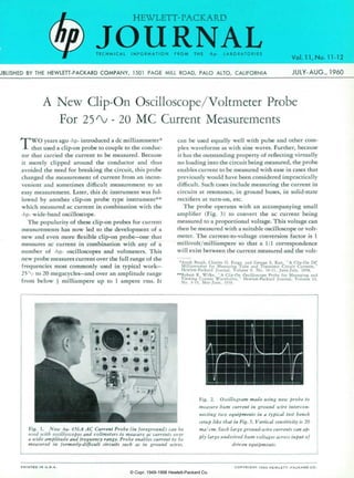
  • 1. HEWLETT- PACKARD JOURNAL T E C H N I C A L I N F O R M A T I O N F R O M T H E - h p - L A B O R A T O R I E S J B L I S H E D B Y T H E H E W L E T T - P A C K A R D C O M P A N Y , 1 5 0 1 P A G E M I L L R O A D , P A L O A L T O , C A L I F O R N I A Vol. 11, No. 11-12 JULY- AUG., 1960 A New Clip-On Oscilloscope/Voltmeter Probe For 25^-20 MC Current Measurements TWO years ago -hp- introduced a dc milliammeter that used a clip-on probe to couple to the conduc tor that carried the current to be measured. Because it merely clipped around the conductor and thus avoided the need for breaking the circuit, this probe changed the measurement of current from an incon venient and sometimes difficult measurement to an easy measurement. Later, this dc instrument was fol lowed by another clip-on probe type instrument which measured ac current in combination with the -hp- wide-band oscilloscope. The popularity of these clip-on probes for current measurements has now led to the development of a new and even more flexible clip-on probe— one that measures ac current in combination with any of a number of -hp- oscilloscopes and voltmeters. This new probe measures current over the full range of the frequencies most commonly used in typical work— 25/V to 20 megacycles— and over an amplitude range from below £ milliampere up to 1 ampere rms. It can be used equally well with pulse and other com plex waveforms as with sine waves. Further, because it has the outstanding property of reflecting virtually no loading into the circuit being measured, the probe enables current to be measured with ease in cases that previously would have been considered impractically difficult. Such cases include measuring the current in circuits at resonance, in ground buses, in solid-state rectifiers at turn-on, etc. The probe operates with an accompanying small amplifier (Fig. 3) to convert the ac current being measured to a proportional voltage. This voltage can then be measured with a suitable oscilloscope or volt meter. The current-to-voltage conversion factor is 1 millivolt/milliampere so that a 1:1 correspondence will exist between the current measured and the volt- •Arndt Bergh, Charles O. Forge, and George S. Kan, "A Clip-On DC Milliammeter for Measuring Tube and Transistor Circuit Currents," Hewlett-Packard Journal, Volume 9, No. 10-11, June-July, 1958. "Robert R. Wilke, "A Clip-On Oscilloscope Probe for Measuring and Viewing Current Waveforms," Hewlett-Packard Journal, Volume 10, No. 9-10, May-June, 1959. Fig. 1. New -hp- 456A AC Current Probe (in foreground) can be used with oscilloscopes and voltmeters to measure ac currents over a wide be and frequency range. Probe enables current to be measured in formerly-difficult circuits such as in ground wires. Fig. 2. Oscillogram made using new probe to measure hum current in ground wire intercon necting two equipments in a typical test bench setup like that in Fig. 5. Vertical sensitivity is 20 ma/ cm. Such large ground-wire currents can ap ply large undesired hum voltages across input of driven equipments. P R I N T E D I N U . S . A . C O P Y R I G H T I 9 6 0 H E W L E T T - P A C K A R D C O . © Copr. 1949-1998 Hewlett-Packard Co.
  • 2. Fig. 3. which current probe consists of clip-on head and transistorized amplifier which can be used with oscilloscope or ac voltmeter. age applied to the oscilloscope or volt meter. Current readings can thus be taken directly from the voltage cali brations on the oscilloscope or voltme ter. Table I presents a list of -hp- instru ments with which the probe can be used. L O W C I R C U I T L O A D I N G Electrically, the probe consists of the secondary winding of a wide-range current transformer for which the con ductor being measured becomes a sin gle-turn primary. To accommodate the clip-on action, the secondary is wound on a split core which opens and closes with the probe jaws. The whole assem bly is magnetically and electrostatically shielded from external fields and elec trostatically shielded from the primary conductor. An extremely valuable feature of such a probe is that it can be designed to reflect very little impedance into the circuit being measured. For the new probe the loading reflected into the measured circuit is less than 50 milli- ohms in series with 0.05 microhenry. Because this loading is so small, currents can be measured in the formerly-diffi cult cases noted earlier such as in ground buses. The measurement of ground-wire currents, in fact, is probably consider ably more valuable than is generally realized. At power line frequencies cur- T A B L E I - d p - I N S T R U M E N T S F O R U S E W I T H 4 5 6 A A C C U R R E N T P R O B E -hp- Voltmeters 400D 400H 400L 403A Wave Analyzer 302A -hp- Oscilloscopes 120A 122 A 130B 150A 160B 170A rents of surprising magnitude can flow in the leads that interconnect the chassis of several equipments. This is true not only of unshielded ground wires where stray magnetic fields may induce the currents, but can also occur from a number of other causes. Fig. 5, for example, illustrates how the use of 3 -prong type power cable plugs will transfer a significant portion of a volt age drop in a ground bus to the input terminals of an equipment. The current measured in a setup like that in Fig. 5 is shown in Fig. 2 (front page). This current, with a peak amplitude of more than 50 ma, could easily cause a hum signal of 0.1 millivolt to be impressed at the input terminals of an equipment connected in the setup of Fig. 5. The source of currents like that in Fig. 2 can often be traced to other equipments and devices connected to the power line. Where such equipments have capacity, or sometimes leakage, to their frame or chassis and where the frame or chassis is grounded to the bus to which the third prong on a power Fig. 4. Probe head clip-on jaws are op erated by flanges on probe body. cable connects, these large and trouble some currents may be encountered. P R O B E F R E Q U E N C Y R E S P O N S E The probe has a wide and constant frequency response (Fig. 6) that per mits it to be used with a variety of volt meters and oscilloscopes. With most of these instruments, the probe response is sufficient that current can be meas ured up to the high-frequency limit of the companion instrument without consideration of the probe's frequency characteristics. This is the case, for ex ample, for all of the instruments listed in Table 1 except the 170 A 30-mc os cilloscope. It should also be noted that with most of these instruments the overall low frequency response of the combination will be primarily that of the probe. In the general case the high-frequency response is somewhat affected by the load capacity into which the probe am plifier is operated. Since the widest fre quency-range instrument with which the probe is likely to be used is the wide band type of oscilloscope, the probe am plifier has been designed to achieve wid est frequency response when operated into the load capacity typical of this type of oscilloscope (approx. 25 mmf ) . This arrangement automatically gives the probe and amplifier the optimum bandwidth for the companion instru- OTHEREQUIPMENT SET-UPBEINGTESTED POWER I L I N E i l T  ¡ " T I ' > T <••'•leakage GROUNDBUS <* 'Ehumcclgnd x Rgnd^ J¿. *-WIRERESISTANCE  ¿ A A A * gnd — ** Rgnd POWERLINEGND Fig. chassis equipment illustrating how capacity from power circuit to chassis in equipment connected to power line ground bus produces hum at terminals of other equipments grounded to same bus. Oscillogram on front page is of hum current in ground lead between units being tested in set-up like this as measured with new probe. © Copr. 1949-1998 Hewlett-Packard Co.
  • 3. 10 100% > 10MC20MC FREOUENCï Fig. 6. Typical frequency response of -dp- Model 456 A Current Probe when operated into rated load. ment with which it is used. For cases where the probe is to be used with other equipment, the curve of Fig. 7 can be used to determine the resulting high frequency response. Figs. 6 and 7 both assume that the resistive portion of the load into which the probe amplifier is operated is 1 00 or more kilohms. Smaller load resistances can be used, however, with some loss in accuracy. Amplitude-wise, the probe calibra tion is adjusted at 1 kc to be accurate within ±%. The frequency response is then sufficiently constant that overall accuracy remains within an additional ± 1 % from a few hundred cycles to above a megacycle. F A S T P U L S E R E S P O N S E The wide bandwidth of the probe head and its amplifier gives the overall instrument a fast rise time of approxi mately 20 millimicroseconds and an otherwise accurate fast pulse response, as demonstrated by the oscillogram of Fig. 8. The rise time illustrated in Fig. 8 approximates that of the faster wide band oscilloscopes and thus makes the probe very valuable in fast circuit ap plications. This value applies not only to the measurement of current but in +2-1 0 - some cases to the investigation of volt age, as discussed below. Where speed or rise time of the meas uring equipment is a factor, it is inter esting to note that the probe may give faster response time when used with a fast oscilloscope than is obtained when the oscilloscope is used in the usual way for voltage measurements. One com mon situation where this is true is where a measurement is to be made of the voltage rise time across a plate load resistor of some hundreds or more ohms. In such a case the capacity of some 10 to 30 mmf added by the oscilloscope when making a voltage measurement will increase the time constant of the resultant R.C combination and slow the speed of measurement. A plate load re sistor of 1,000 ohms, for example, when shunted by 20 mmf has a 10-90% rise time of 44 millimicroseconds. The new current probe, on the other hand, can be used in this same situation by clipping to the "cold" end of a plate load resistor where the probe adds no effective capacity. In this case the probe rise time of 20 millimicroseconds, al though it may be modified somewhat by the rise time of the oscilloscope used, may still be significantly faster than the rise time obtained in a voltage meas urement. -6- IMC 1 0 M C FREQUENCY 30MC Fig. various load high frequency response of probe when used with various load capacities. Probe has been designed so that optimum frequency response occurs with 25 mmf capacities typical of wide-band oscilloscopes. Fig. 8. Fast pulse response of current probe as displayed by -hp- 1 70 A wide-band oscilloscope. Sweep time is 0.05 ¡isec/cm, showing probe 10-90% rise time of 0.02 fisec. Another case where the probe often proves superior to the voltage-across- resistance method of measuring current is demonstrated by the oscillograms in Fig. 9. These oscillograms show meas urements made of the current in the emitter circuit of a pulsed transistor. The upper oscillogram was made by in serting a 1-ohm resistance in the emit ter circuit and measuring the resulting voltage drop with the oscilloscope. The second oscillogram was made with the 1-ohm resistance removed from the cir cuit and with the probe connected to give the current reading directly. In both cases the current scale is the same. If these two oscillograms are com pared, it will be seen that the voltage- derived measurement shows consider ably more overshoot as well as a current value about 10% lower than in the case where the current value was measured with the probe. The overshoot arises from the voltage drop occurring across the inductance of about % " of lead on the resistor. The 10% change in current occurs from the effect of the 1-ohm re sistor in the emitter circuit. (b) Fig. 9. Oscillograms contrasting pulse waveforms obtained in grounded-emitter transistor using two measurement tech niques. Upper trace shows voltage wave form across 1-ohm resistor with large overshoot produced by lead inductance. Lower trace shows more accurate current waveform obtained using new probe. © Copr. 1949-1998 Hewlett-Packard Co.
  • 4. Fig. 10. Close-up view of -dp- 456/4 AC Current Probe. L O W F R E Q U E N C Y RESPONSE The low frequency amplitude re sponse, as indicated in Fig. 6, is such that the probe can be used to measure currents down to virtually the lowest audio frequencies, since the lower 3-db point is rated at 25 cps. This extended low frequency response has the addi tional value that it enables the probe to measure relatively long pulses with little resultant sag. In measuring recti fier currents at power line frequencies, however, there will be a moderate wave form distortion due to phase shift at 60 or 120 cps. This distortion, though, does not prevent determination of the peak current or conduction angle. Fig. 1 1 illustrates this point by showing the waveform obtained when a measure ment was made with the probe of the current in one rectifier of a bridge rec tifier circuit using solid-state rectifiers. This is an otherwise-difficult measure ment that could scarcely be made with out the probe. In determining the peak value of a waveform such as that shown in Fig. 11, it is convenient to position the waveform vertically on the oscilloscope so that the lower corners of the pulse are equally-spaced about one of the horizontal graticule lines as shown. The peak pulse current can then be read from this line to the pulse peak. M E A S U R I N G D I S T O R T I O N I N C U R R E N T W A V E F O R M S When working with audio frequencies it is often desirable to obtain informa tion concerning the harmonic distor tion in current waveforms. Frequently, this information can be obtained by measuring the distortion in a voltage waveform related to the current in question. In other cases, however, the current flows through a non-linear im pedance so that the resulting voltage waveform is not suitable for a distor tion measurement. One such situation occurs when a signal current flows into the non-linear emitter circuit of a tran sistor. Here, the voltage waveform will not produce the needed distortion in formation, since the transistor opera tion is related to input current. For such instances the new current probe can be used with the -hp- Model 3 02 A Wave Analyzer to obtain an analysis of the current waveform. The Model 3 02 A measures components up to 50 kc and has a narrow bandwidth which in transistor applications is bene ficial in reducing the effect of transistor noise on the measurement. Harmonic components 30 db or more below 1 milliampere can ordinarily be meas ured with this arrangement. Distortion measurements can be made with negli gible contribution from the probe it self, a typical value for this contribu tion being 70 db below 1 0 milliamperes at 1 kc. Similarly, dc currents of the magnitudes typically encountered in *J. R. Petrak, "A New 20 CPS— 50 KC Wave Analyzer with High Selectivity and Simplified Tuning," Hewlett-Packard Journal, Volume 11, No. 1-2, Sept.-Oct., 1959. Fig. 11. Current pulses in one leg of bridge type power rectifier circuit as measured with new probe. circuit work have little effect on the probe distortion. MICROAMPERE-RANGE CURRENTS The combination of the new probe and the Model 302A Harmonic Wave Analyzer can also be used for measur ing very small alternating currents in the frequency range from 20 cps to 50 kc. On its most sensitive range the Model 302A measures voltages of 30 microvolts full scale so that this range, when combined with the 1 mv/ma con version factor of the probe, permits currents below 30 microamperes to be measured. The method thus offers a means of measuring such small currents as the base current in transistors. Even though such currents are below the nominal noise level of the probe (50 jita),, the measurement can still be made because of the filtering effect of the wave analyzer's selectivity character istic. The measurement of small currents with the wave analyzer can also be fa cilitated by the fact that the analyzer makes available for external use a sig nal (BFO output) which is the same in frequency as the frequency to which the analyzer input is tuned. Use of this signal to drive a circuit under test often eliminates the need for an external sig nal source and can greatly assist in measuring a signal current in the pres ence of noise. (Concluded on page 6) Transistor under test N -hp- 302A WAVEANALYZER Fig. distortion Probe can be used with -hp- 302 A Wave Analyzer to measure distortion in current waveforms or to measure small audio currents, as described in text. •4• © Copr. 1949-1998 Hewlett-Packard Co.
  • 5. THE VALUE OF AC CURRENT MEASUREMENTS Fig. 1. Oscillogram of plate voltage (upper trace) and plate current (lower trace) of Class C-pentode measured us ing -dp- 456/4 current probe with dual- channel oscilloscope. Note sine-wave current component along base line of lower trace. Fig. 2. Oscillogram showing screen current (upper trace) and plate current (lower trate) of same tube as in Pig. 1 measured using two 456 A current probes with dual-channel oscilloscope. Upper trace has twice the sensitivity of lower trace. Experience with the -hp- clip-on current probes has frequently and consistently shown that the conven ience with which these probes enable current to be measured leads to infor mation that would not otherwise be obtained. A case in point is demon strated by the accompanying oscillo- grams. The upper waveform in the first Oscillogram shows the plate voltage waveform on a pentode operat ing in a class C stage. From all appear ances this waveform is conventional and does not indicate much about the operating conditions of the tube. Im mediately below the plate voltage waveform in Fig. 1, however, is the plate current waveform as measured with the new Model 45 6 A Current Probe and displayed by an -hp- Model 16 OB dual-trace oscilloscope. This plate current waveform shows at once that the plate is being driven below the knee of the plate current-plate voltage characteristic. At the current peaks the plate current is notched, in dicating that the plate is bottoming and thus losing current to the screen. It is also interesting to note that the current base line, instead of showing zero current, shows a sine-wave cur rent component which is the current chat flows mainly through the plate capacitance of the tube. In Fig. 2 the upper trace shows the screen-grid current, while the lower trace again shows the plate current for the same tube as in Fig. 1. The oscil- logram was made by using two of the current probes simultaneously. For convenience the screen current is shown at twice the sensitivity of the plate current. It is readily apparent that the lost pulses of plate current are drawn by the screen. The screen also shows a sine-wave component of capacitive current. C U R R E N T S U M M I N G A N D E Q U A L I Z I N G Since the probe is effectively a cur rent transformer, it has the property that it will algebraically sum the in stantaneous value of the currents in two or more conductors it may be clipped around. This property makes the probe a valuable and easily-applied tool in applications in which it is de sired to equalize or balance ac cur rents. In the case involving the class C stage described above, for example, it is possible to use this summing prop erty to examine the plate current pulses exclusive of the current com ponent flowing through the capacity of the tube. This would then easily permit the angle of plate current flow to be measured. Fig. 3 shows the re sult when this is done. In Fig. 3 the same plate current pulses as in Fig. 2 are shown, except at twice the display sensitivity. In Fig. 2 the capacitive component is present, while in Fig. 3 this component has been bucked out. The method used to obtain the buck ing current is indicated in Fig. 4. The probe was clipped around the plate lead of the tube, but at the same time a lead from an external variable ca pacitor was connected to the plate lead and passed through the probe as Fig. 3. Same plate current as in fig. 2 but with capacitive component bucked out using technique indicated in Fig. 4 and described in text. -hp- 456A PROBE HUD Fig. 4. Arrangement used to buck out capacitive component of plate current. shown. By suitably adjusting the vari able capacitor, a capacitive current equal but opposite to the capacitive current flowing at the plate can be ap plied to the probe. For display pur poses the tube's electron current is thus separated from the capacitive current. It is abo interesting to note that the arrangement shown in Fig. 4 pro vides a dynamic measure of the out put capacity of the tube. This occurs because the final setting of the varia ble capacitor should be equal to the tube output capacity. The probe is valuable in a number of other current-equalizing applica tions. Especially common among these are equalizing the input and output currents in push-pull and balanced circuits in both transistor and tube applications. © Copr. 1949-1998 Hewlett-Packard Co.
  • 6. Fig. 13. -hp- Model 456A Current probe as used with -dp- Model 400D VTVM. HIGHER SENSITIVITIES Under some if not many circum stances, the basic 1 mv/ma sensitivity of the probe can be increased two or more times by looping additional turns of the conductor being measured through the probe head. Looping turns in this way will increase the probe sen sitivity in proportion to the number of times the conductor passes through the head and will do so without increasing the nominal noise level of the probe. The main considerations involved in this method of increasing sensitivity are the additional self -inductance that the looping causes in the primary con ductor and the effect of this self-in ductance in combination with the loop- to-loop capacitance of the conductor. This combination can result in a reson ance in the low megacycle region. Where this resonance is not a factor, however, and where physical factors permit, as many as 10 turns can be used in this way. I N S U L A T I O N C O N S I D E R A T I O N S The exterior surfaces of the probe head are molded from an electrically- insulating plastic so as to preclude the possibility of shock when the probe is clipped on a conductor that is at an ac and/or dc voltage. However, the in terior surfaces of the aperture that re ceives the conductor to be measured necessarily consist of metallic parts to achieve the desired electrostatic and magnetic shielding for the probe head. These parts are electrically connected to the low terminal of the plug that interconnects the probe to its compan ion instrument. Since insulating these shield parts would seriously diminish the electrical and mechanical usefulness of the probe, it has been deemed more advantageous to the user to arrange the probe to rely on the insulation of the conductor being measured to electri cally isolate the probe from any voltage on the conductor. Hence the probe should be used only with adequately in sulated conductors when a voltage exists on the conductor. Normally, this requirement imposes no serious incon venience, since conductors with signifi cant voltage will often already be in sulated. Where bare conductors off ground are encountered, it is usually adequate to insulate a portion of the conductor by a turn or two of electrical insulating tape. It is also often conven ient merely to clip the probe around a small insulated composition resistor where one is in the circuit. In addition to the conductor insula tion consideration, the low side of the double plug on the output of the probe amplifier should for personnel safety be connected only to the equipment termi nal that is solidly grounded to a power line system ground. G R O U N D L E A D The probe head is provided with a detachable ground lead (Fig. 10) which is occasionally useful in fast circuit work. If the oscilloscope used with the probe has significant response at 1 5 me and higher and the circuit under meas- 1 1 f < i r > - n i r - i t - K i c o n o v r r T r i f f i a r a f f C Q U K O â € ” cies, it is desirable to use the ground lead to connect the probe head to the chassis under test. This will short stray capacities and minimize undesired spur ious responses that may be formed with such capacities. At these frequencies solid grounding between the oscillo scope, probe amplifier chassis, and chassis under test are also generally necessary. BATTERY OR P O W E R L I N E OPERATION The amplifier for the probe has been designed as a transistorized amplifier to achieve the advantages of long life, small size, and light weight. Transis torization has also made it practical to arrange the amplifier to be battery-op erated, thereby achieving portability as well as a lower selling price, although the amplifier is also available in an ac- operated version. The two versions are identical in size and appearance. Battery operation also has perform ance advantages because the residual noise level of the amplifier is somewhat lower in the battery-operated version. G E N E R A L The probe has several other conven iences which are worthy of mention. As a convenience in pulse work, the head is marked with an arrow to relate the direction of conventional current flow in the conductor being measured to the resulting positive voltage at the probe output terminals. The probe aper ture is large enough (5/32" diameter) to accept most conductors usually found in electronics work. Head shield ing from external magnetic fields is such that these are seldom troublesome, but in any case a check can be made merely by holding the probe with closed jaws in the region of interest to see if a reading occurs. Electrically, the probe has a capacity of only about 4 mmf to the conductor measured and consequently only a slight conductor voltage effect of 0.03 ma/volt-megacycle. In most cases this is too small to be noticed. Similarly, the effect of dc in the measured conductor is normally insignificant, since half an ampere of dc at the lowest audio fre quencies or several amperes at higher frequencies are required before an effect is noticeable. ACKNOWLEDGMENT The design group for the new probe was headed by George S. Kan and in cluded Hudson F. Grotzinger, who per formed the mechanical design, in addition to the undersigned. —Charles O. Forge S P E C I F I C A T I O N S - / i p - M O D E L 4 5 6 A A C C U R R E N T P R O B E S e n s i t i v i t y : 1 m v / m a  ± 1 % a t 1 k c . Frequency Response: ± 2%, 100 cps to 3 me. ± 5%, 60 cps to 4 me. -3 db, 25 cps to 20 me. Pulse Response: Rise time is less than 20 nano s e c o n d s ; s a g i s l e s s t h a n 1 6 % p e r m i l l i second. M a x i m u m I n p u t : 1 a m p r m s ; 1 . 5 a m p p e a k . 100 ma above 5 me. Effect of DC Current: No appreciable effect on sensitivity and distortion from dc current up to 0.5 amp. Input Impedance: (Impedance added in series with measured wire by probe). Less than 50 milliohms in series with .05 /¿h. (This is ap p r o x i m a t e l y t h e i n d u c t a n c e o f 1 V 2 i n . o f hookup wire). P r o b e S h u n t C a p a c i t y : A p p r o x i m a t e l y 4 p f a d d e d f r o m w i r e t o g r o u n d . Distortion at 1 KC: For '/2 amp input at least 50 db down. For 10 ma input at least 70 db down. Equivalent Input Noise: Less than 50 /¿a rms (100 /¿a when ac powered). Output Impedance: 220 ohms at 1 kc. Approxi m a t e l y - f - 1 v d c c o m p o n e n t . S h o u l d w o r k i n t o l o a d o f n o t l e s s t h a n 1 0 0 , 0 0 0 o h m s shunted by approximately 25 pf. Power: Battery-operated with mercury-cell type batteries furnished; battery life is approxi mately 400 hours. Ac power supply optional at extra cost, 115'230 v ± 10%, 50 to 1000 cps; approx. 1 watt. Weight: Net 3 Ibs. D i m e n s i o n s : 5 i n . w i d e , 6 i n . d e e p , 1 T / 2 i n . high. Probe cable is 5 ft. long; output cable i s 2 f t . l o n g a n d t e r m i n a t e d w i t h a d u a l banana plug. Price: -hp- Model 456A with batteries, $190.00. -np- Model 456A with ac supply (456A-95A) installed in lieu of batteries, $210.00. Prices f.o.b. Palo Alto, California Data Subject to change without notice © Copr. 1949-1998 Hewlett-Packard Co.