
Recommended
Recommended
More Related Content
Similar to 16SMCE310 16SCVE310 – Engineering Skills Project Brief .docx
Similar to 16SMCE310 16SCVE310 – Engineering Skills Project Brief .docx (20)
More from felicidaddinwoodie
More from felicidaddinwoodie (20)
Recently uploaded
Recently uploaded (20)
16SMCE310 16SCVE310 – Engineering Skills Project Brief .docx
- 1. 16SMCE310 / 16SCVE310 – Engineering Skills Project Brief: Flume Ride Introduction Employers are constantly asking for engineering graduates who have good team skills, are problem solvers and are good communicators. On top of that, engineers need to be creative and innovative. They have to work with many constraints, while developing safe products and solutions to help the community. Your team is working on a large project at a consulting engineering firm in Kuwait. Your boss has approached you to find a solution to a problem. Given that the current engineering tasks on the project all seem to involve the same standard, your boss asks your team to design and build a fully functional Flume Ride within a proposed Fun Park on a piece of land near to the sea shore in Salmiya. Project description
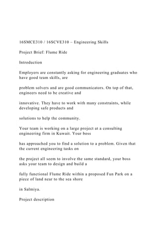
- 2. A Flume Ride is a balance between safety and sensation. Naturally, the ride should be as safe as possible. After all, if the people are injured riding the Flume Ride then there would be fewer repeat riders. Fewer repeat riders mean a short life span for the Flume Ride. No to mention the severe legal implications that could be imposed on the owner of the Flume Ride and the engineers responsible for the design. Keeping in mind that passengers ride a Flume Ride for the “death defying” thrill. Here, the key to be successful is to give the rider the sensation of speed and acceleration. It all comes down to speed control. To achieve this, the hills, curves, dips, and straight always are not randomly designed. Your job as an engineer is to design a simple Flume Ride similar to the attached figure. The track starts with an inverse vertical curve followed by a ramp as shown in the figure. The car should reach the small water pool at the end. You are also responsible for designing the Flume Ride car. In this project, you are expected to discuss and document some of the principals
- 3. involved in real-life design. You are also responsible for building the Flume Ride and the car. Requirements: The owner (represented by your Instructor) has constraints regarding the material to be used. Each team member needs to develop individually a design idea, to analyse the structure using hand calculations or software (i.e. SOLIDWORKS, AutoCAD, Staad.Pro, etc.). Your team needs to discuss advantages and disadvantages of the design ideas, showing your evaluation criteria on a decision matrix. Other requirements are: 1. The Flume Ride MUST BE inherently safe. The car should not fall off the track. 2. The minimum clearance between ground and Roller Coaster track should be 0.5 m. 3. The maximum height of the Flume Ride track should be 1.5 m. 4. The maximum plan area in which the Flume Ride is built in is 2.25 m2 (1.5m×1.5m). 5. The maximum Flume Ride track width is 0.15 m. 6. SOLIDWORKS must be used to design the Roller Flume
- 4. Ride. 7. Flume Ride car should be manufactured using 3D printing technology. 8. Flume Ride car should be designed to carry 1.5 kg load. 9. The Flume Ride track should be made of wooden sticks or a sheet metal based on truss shapes. 10. The weight of the whole Flume Ride structure should be as light as possible. 11. The Flume Ride structure must be able to withstand the rolling car and an additional 1.5 kg of extra load. 12. All joints need to be pin joints (using wires) or be glued. 13. All work has to be carried out on-campus. 14. The Flume Ride has to be ready for testing in week 12. Students of the winning team who best meet the requirements will be awarded the “Flume Ride design competition certificate”, awarded by ACK’s School of Engineering. Project Submission Each team is responsible for submitting a complete design a
- 5. technical report that must contain some of the following engineering fundamentals: 1. Design and additive manufacturing (3-D printing) fundamentals: a) Apply your engineering skills to design the best Flume Ride to meet the requirements given, showing all valid and clear assumptions. b) Show all of your calculations including your safety factors. Your team needs to discuss advantages and disadvantages of your design ideas, showing your evaluation criteria on a decision matrix. c) Determine any other design related calculations and/or assumptions d) Complete your design using CAD software (i.e. SOLIDWORKS, AutoCAD, etc.). 2-D drawings are required for your technical report. 3-D models are needed for additive manufacturing purposes and they are expected to be presented on your final presentation e) Convert your 3-D models to the appropriate format (i.e. STL, STEP, etc.) so you
- 6. can make your car and any other required materials using additive manufacturing (3-D printer). 2. Statics & Dynamics principles: a) Calculate all forces required for the car and the Flume Ride structure including the shear, compressive, and axial loads (columns). b) Work out and detail all governing equations and those resulted from the car motion at each element of the track. c) Plot the axial forces vs. the track length d) Provide a graph of car speed with the additional weight vs. track length 3. Physics Principles: a) Apply and show all related physics calculations b) Determine all energy analysis at each element of the track resulted from the motion of the car c) Graph total energy vs. track length
- 7. 4. Mathematical principles (equations representing the adopted track) The following nontechnical principles are also expected to be submitted in your technical report: 1. Decision Matrix 2. Risk Assessments 3. Project Plan (Gantt chart) DEADLINES: The design must be completed by the end of week 11 to be tested on week 12. The technical report is due to be submitted with your portfolio on December 1st, 2016 at 12:00pm. A Guide to Technical Report Writing Australian College of Kuwait
- 8. School of Engineering Engineering Skills (ENEG11001) 1. Introduction Technical report writing is an essential part of engineering communication - you are communicating the results of your work to someone else. Once ‘published’, your technical reports will become a long- lasting record of your proficiency and ability as an Engineer. The following topics will be discussed: • General report layout and presentation • Report sections • Report formatting • Tables, figures and graphs 2 2. General Report Layout and Presentation
- 9. The key points in effective written communication in technical report writing are: • Logical and neat presentation • Clarity • Concise expression • Continuity between sections When you write a report be mindful of the purpose of the report. More is not necessarily better – give enough detail so that you present a convincing case. Third person, past tense is generally accepted. 3 2. General Report Layout and Presentation Some important points to note: • Only print on one face of each page • Bind the report so that it is easy to read and ensure that no part of the report is concealed by the binding • Ensure that tables, figures etc. are not ‘fragmented’ over two pages • Ensure that a section heading is not separated from the section text due to end of page/start of new page
- 10. • Use a spellchecker but be aware that it will not pick up incorrect usage of words eg. there/their. 4 3. Report Sections • Title Page • Executive Summary • Table of Contents • List of Figures/Tables • Abbreviations • Acknowledgements • Introduction • Literature Review • Methodology • Results and/or Discussion • Conclusion • Reference List • Appendices 5 3. Report Sections • Please note, that while there is a basic standard layout for technical report writing, you must accept the possibility of variations in requirements for different ‘clients’.
- 11. • You must be flexible and adaptive in these circumstances. • You need to be certain of the requirements for a specific report. 6 3. Report Sections 3.1 Title Page This should clearly show the name of the client, the report title, report date, the author’s name and the author’s organization. The Title Page is the first page of the report to be viewed by the reader and should show the above information clearly, and be well presented. 7 3. Report Sections 3.2 Executive Summary The Executive Summary is best left until the rest of the report
- 12. is written. A concise summary of the work contained in the report should be given. The Summary should be brief, but not omit any important information. Abbreviations should only be used when they are acceptable. The Summary should ‘stand alone’ without reference to any other part of the report, and include the main results of the work. 8 3. Report Sections 3.3 Table of Contents (TOC) Should be generated once the report is complete. If you use the Word heading styles, you can get Word to generate the TOC for you. Example: Executive Summary ii Table of Contents iv Acknowledgements ix
- 13. 1 Introduction 1 1.1 Brief overview of the Australian Sugar Industry 2 9 3. Report Sections 3.4 List of Figures/Tables Should be generated once the report is complete. If you use the Word captioning, you can get Word to generate the list for you. Example: Table 2.1 Comparing CLP and IP 74 Table 4.1 Cane schedule results 142 10 3. Report Sections 3.5 Abbreviations You can generate this as the report is compiled. You should also put the full name and the abbreviation the first time it is
- 14. used in the text. eg. … many well-known operations research (OR) problems … After the first time, you can use just the abbreviation in the text. eg. … is a well known OR problem that has been … 11 3. Report Sections 3.6 Acknowledgements This is where you acknowledge help or resources that particular people or organizations have given you. 12 3. Report Sections 3.7 Introduction The origin, purpose, scope and objectives of the work should be briefly outlined in the Introduction to enable the reader to assess the significance and value of the work. If needed, the Introduction can include a discussion of the theoretical background for the work. If this is extensive, a
- 15. separate section may be justified. The Introduction ‘lays the groundwork’ for the more detailed statements and discussions in the body of the report. 13 3. Report Sections 3.8 Literature Review The Literature Review is an account of what has been published on this topic by others. It is part of the introduction to your report. In writing the Literature Review, your purpose is to convey what knowledge and ideas have been established on a topic. Your Literature Review should: • Be organized around & related directly to your project • Identify areas of controversy in the literature (if any) • Identify a best method of approach to solving the project objective 14 3. Report Sections
- 16. 3.9 Methodology A detailed description of how you performed the work in this project. This should include engineering calculations and other technical information required for the work that occurred. 15 3. Report Sections 3.10 Results and/or discussion Detail all your results and/or discussion. This may include data presented in graphs etc. Should include a critical examination of results and possibly a comparison of results with theory if relevant. 16 3. Report Sections 3.11 Conclusion A short summary highlighting the project results, outcomes and how these met the objectives. A summary of results by itself is not a conclusion.
- 17. Recommendations may be made in this section, but if the recommendations form a substantial part of the report, include them as a separate section. 17 3. Report Sections 3.12 Reference List List all reference material used to conduct the work and produce the report. Reference material may include textbooks, websites, journal articles, other publications/reports etc. We will look at referencing in more detail later in this presentation. 18 3. Report Sections 3.13 Appendices The Appendix of a report should be used to include relevant information to support the contents or subject of a report.
- 18. The Appendix can also be used to include large parts of the report (such as pages of test data) that are part of the work but if included in the body of the report, would detract from the report ‘readability’. 19 4. Report Formatting 4.1 Page Numbering Pages prior to the Introduction such as the Table of Contents should be numbered using lower case Roman numerals, for example - i, ii, iii, iv, etc. You can set the numbering style in Word under The Title Page is usually page i but the number is not shown on the page. The Introduction is page 1. To change the page numbering Introduction. Then on the Introdu 20 4. Report Formatting 4.2 Section Numbering
- 19. Each section of the report should be numbered starting with the Introduction as Section 1, for example: Executive Summary Table of Contents Acknowledgements 1. Introduction 2. Literature Review 3. Methodology 4. Results 5. Conclusion Reference List A. Data from Experiment 1 B. Sketches 21 4. Report Formatting 4.2 Section Numbering Sub-sections should be numbered as follows: 3 Methodology 3.4 Mathematical Formulation of the Problem 3.4.1 Known quantities 3.4.2 Calculating the total number of activities Use the heading styles in Word then Bullets and numbering If you do this, Word will generate the TOC (table of content)
- 20. for you including the section numbers & page numbers. 22 4. Report Formatting 4.2 Section Numbering Appendices B Data In order to get Word to do this properly you will need to start a new Section and generate your own heading styles eg. Appendix 1 etc. 23 5. Tables, Figures and Graphs Tables should be numbered using upper case Roman numerals: Table III Table IV The Table number and description should appear above the Table. (example to follow)
- 21. Figures should be numbered using Arabic numerals: Figure 1 Figure 6 The Figure number and description should appear below the Figure. (example to follow) Figures can be drawings, diagrams, photos, graphs etc. 24 5. Tables, Figures and Graphs Table III: Comparison of experimental and theoretical bending stress. Load (N) Experimental Bending Stress (MPa) Theoretical Bending Stress (MPa) Variation (%) 0 10
- 22. 20 30 40 0 25 5. Tables, Figures and Graphs Driver Mounted Accelerometer Upper back or neck. Cushion Base plate Legend Acceleration Direction of Measurement Cabin Floora,b c d e f g
- 23. Figure 1: Accelerometer locations and orientation. 26 5. Tables, Figures and Graphs Lever Arm 1 - Torque verses Rotation 0.00 2.00 4.00 6.00 8.00 10.00 12.00 0.00 1.00 2.00 3.00 4.00 5.00 6.00 7.00 8.00 9.00 10.00 11.00 12.00 Rotation (degrees) T o rq u
- 24. e ( k N m ) Figure 3: Torque verses Rotation for lever arm 1. 27 6. Referencing You should reference to: • Show support for a statement • Show how your work relates to other people’s work • Allow readers to find out more information • Acknowledge your sources • Justify your claims You can find information on referencing in the following document: “Abridged Harvard Referencing Guide_2013.pdf” on the homepage of this course on PowerCAMPUS Engineering uses the Harvard (author-date) system of referencing.
- 25. 28 6. Referencing Referencing in-text examples: … of which 35.6 million tonnes were crushed in Queensland (Australian Bureau of Statistics 2000). Dalfiume et. Al. (1995) used CLP to schedule trains …. Figure 1.1 Sugar cane growing areas Source: Bundaberg Sugar 1998 29 6. Referencing Reference List example: Australian Bureau of Statistics (ABS) 2000, 7121.0 1998-99, Agricultural Commodities, viewed 21 June 2000,
- 26. www.abs.gov.au. Bratko, I. 1990, Prolog – Programming for Artificial Intelligence, 2nd ed, Addison-Wesley Publishers Ltd. Chow, K.P & Perett, M. 1997, ‘Airport counter allocation using CLP’, Proceedings of Third International Conference on the Practical Application of Constraint Technology PACT ’97, London, pp. 107- 116. 30 http://www.abs.gov.au/ 7. Conclusion Technical report writing is an essential part of engineering communication. You are communicating, in written form, a body of work that is important to your employer or client. As an author, you must present a report that is neat, logical, factual, accurate, clear and concise – your professional ability will be judged by the quality of your written work.
- 27. 31