K. PALANIVEL
SYSTEMS ANALYST,COMPUTER CENTRE
PONDICHERRY UNIVERSITY, PUDUCHERRY – 605014, INDIA.
Routing Protocols (RIP, OSPF, BGP)
COMS 525: TCP/IP
CHAPTER-15
Topic
2.
Introduction
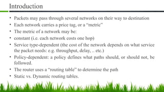
• Packets maypass through several networks on their way to destination
• Each network carries a price tag, or a “metric”
• The metric of a network may be:
• constant (i.e. each network costs one hop)
• Service type-dependent (the cost of the network depends on what service
the packet needs: e.g. throughput, delay, .. etc.)
• Policy-dependent: a policy defines what paths should, or should not, be
followed.
• The router uses a “routing table” to determine the path
• Static vs. Dynamic routing tables.
3.
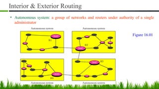
Interior & ExteriorRouting
• Autonomous system: a group of networks and routers under authority of a single
administrator
Figure 16.01
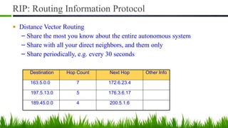
RIP: Routing InformationProtocol
■ Distance Vector Routing
– Share the most you know about the entire autonomous system
– Share with all your direct neighbors, and them only
– Share periodically, e.g. every 30 seconds
Destination Hop Count Next Hop Other Info
163.5.0.0 7 172.6.23.4
197.5.13.0 5 176.3.6.17
189.45.0.0 4 200.5.1.6
7.
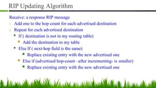
RIP Updating Algorithm
Receive:a response RIP message
1. Add one to the hop count for each advertised destination
2. Repeat for each advertised destination
■ If ( destination is not in my routing table)
■ Add the destination to my table
■ Else If ( next-hop field is the same)
■ Replace existing entry with the new advertised one
■ Else if (advertised hop-count –after incrementing- is smaller)
■ Replace existing entry with the new advertised one
8.
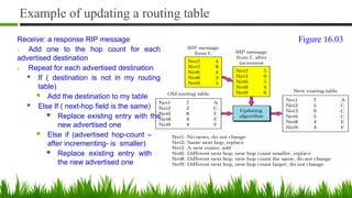
Example of updatinga routing table
Receive: a response RIP message
1. Add one to the hop count for each
advertised destination
2. Repeat for each advertised destination
■ If ( destination is not in my routing
table)
■ Add the destination to my table
■ Else If ( next-hop field is the same)
■ Replace existing entry with the
new advertised one
■ Else if (advertised hop-count –
after incrementing- is smaller)
■ Replace existing entry with
the new advertised one
Figure 16.03
9.
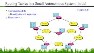
Routing Tables ina Small Autonomous System: Initial
■ Configuration File
Q Directly attached networks
Q Hop-count = 1
Figure 16.04
10.
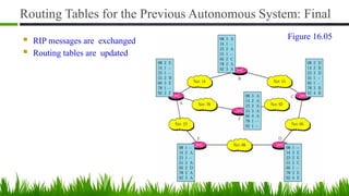
Routing Tables forthe Previous Autonomous System: Final
■ RIP messages are exchanged
■ Routing tables are updated
Figure 16.05
11.
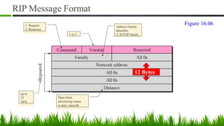
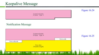
RIP Message Format
12Bytes
1: Request
2: Response
Address Family
Identifier
2: TCP/IP family
1 or 2
up to
25
AFIs
Hops from
advertising router
to dest. network
Figure 16.06
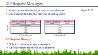
12.
RIP Request Messages
■Sent by a router when booted, or when an entry times-out
■ May request updates for ALL networks, or specific one(s)
RIP Response Messages
■ Solicited responding to a previous request
■ Unsolicited (sent periodically to all neighbors)
Figure 16.07
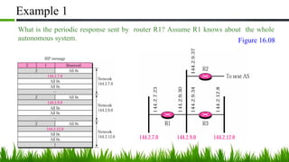
13.
Example 1
What isthe periodic response sent by router R1? Assume R1 knows about the whole
autonomous system. Figure 16.08
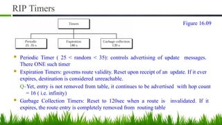
14.
RIP Timers
■ PeriodicTimer ( 25 < random < 35): controls advertising of update messages.
There ONE such timer
■ Expiration Timers: governs route validity. Reset upon receipt of an update. If it ever
expires, destination is considered unreachable.
Q-Yet, entry is not removed from table, it continues to be advertised with hop count
= 16 ( i.e. infinity)
■ Garbage Collection Timers: Reset to 120sec when a route is invalidated. If it
expires, the route entry is completely removed from routing table
Figure 16.09
15.
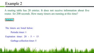
Example 2
A routingtable has 20 entries. It does not receive information about five
routes for 200 seconds. How many timers are running at this time?
Solution
The timers are listed below:
Periodic timer: 1
Expiration timer: 20 - 5 = 15
Garbage collection timer: 5
16.
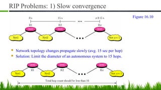
RIP Problems: 1)Slow convergence
■ Network topology changes propagate slowly (avg. 15 sec per hop)
■ Solution: Limit the diameter of an autonomous system to 15 hops.
Figure 16.10
17.
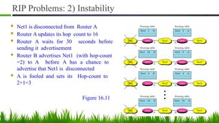
RIP Problems: 2)Instability
■ Net1 is disconnected from Router A
■ Router A updates its hop count to 16
■ Router A waits for 30 seconds before
sending it advertisement
■ Router B advertises Net1 (with hop-count
=2) to A before A has a chance to
advertise that Net1 is disconnected
■ A is fooled and sets its Hop-count to
2+1=3
Figure 16.11
18.
Remedies for RIPInstability
■ Triggered Update:
Q Send an immediate update (with hop count =16) whenever a network becomes
unreachable, otherwise send periodic updates.
■ Split Horizons:
Q Never sent same information back to the interface it came from
Figure 16.12
19.
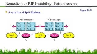
Remedies for RIPInstability: Poison reverse
■ A variation of Split Horizon.
Figure 16.13
20.
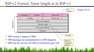
RIP-v2 Format: Samelength as in RIP-v1
■ RIP version 2 supports CIDR.
■ RIP messages are encapsulated in a UDP datagram
■ RIP uses the services of UDP on well-known port 520.
AS
number
or prefix
useful if 2
AS share a
backbone
network
Figure 16.14
21.
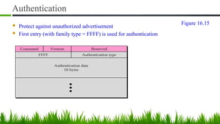
Authentication
■ Protect againstunauthorized advertisement
■ First entry (with family type = FFFF) is used for authontication
Figure 16.15
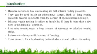
Introduction
• Distance vectorand link state routing are both interior routing protocols.
• They can be used inside an autonomous system. Both of these routing
protocols become intractable when the domain of operation becomes large.
• Distance vector routing is subject to instability if there is more than a few
hops in the domain of operation.
• Link state routing needs a huge amount of resources to calculate routing
tables.
• It also creates heavy traffic because of flooding.
• There is a need for a third routing protocol which we call path vector routing.
24.
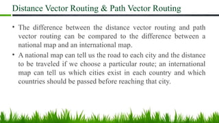
Distance Vector Routing& Path Vector Routing
• The difference between the distance vector routing and path
vector routing can be compared to the difference between a
national map and an international map.
• A national map can tell us the road to each city and the distance
to be traveled if we choose a particular route; an international
map can tell us which cities exist in each country and which
countries should be passed before reaching that city.
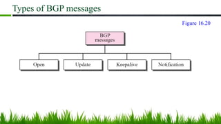
Border Gateway Protocol(BGP)
• Border Gateway Protocol (BGP) is an interdomain routing protocol
using path vector routing.
• It first appeared in 1989 and has gone through four versions.
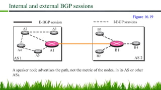
Internal and externalBGP sessions
A speaker node advertises the path, not the metric of the nodes, in its AS or other
ASs.
Figure 16.19
31.
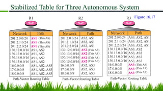
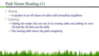
Path Vector Routing(1)
• Sharing
– A speaker in an AS shares its table with immediate neighbors
• Updating
– Adding the nodes that are not in its routing table and adding its own
AS and the AS that sent the table
– The routing table shows the path completely
32.
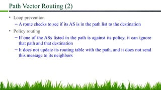
Path Vector Routing(2)
• Loop prevention
– A route checks to see if its AS is in the path list to the destination
• Policy routing
– If one of the ASs listed in the path is against its policy, it can ignore
that path and that destination
– It does not update its routing table with the path, and it does not send
this message to its neighbors
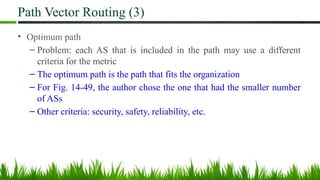
33.
Path Vector Routing(3)
• Optimum path
– Problem: each AS that is included in the path may use a different
criteria for the metric
– The optimum path is the path that fits the organization
– For Fig. 14-49, the author chose the one that had the smaller number
of ASs
– Other criteria: security, safety, reliability, etc.
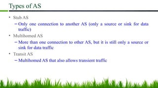
34.
Types of AS
•Stub AS
– Only one connection to another AS (only a source or sink for data
traffic)
• Multihomed AS
– More than one connection to other AS, but it is still only a source or
sink for data traffic
• Transit AS
– Multihomed AS that also allows transient traffic
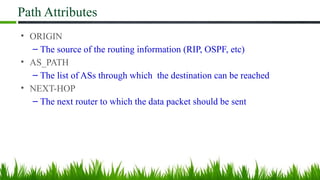
Path Attributes
• ORIGIN
–The source of the routing information (RIP, OSPF, etc)
• AS_PATH
– The list of ASs through which the destination can be reached
• NEXT-HOP
– The next router to which the data packet should be sent
40.
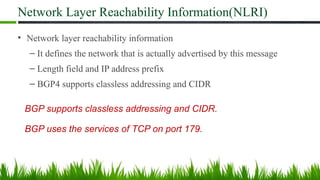
Network Layer ReachabilityInformation(NLRI)
• Network layer reachability information
– It defines the network that is actually advertised by this message
– Length field and IP address prefix
– BGP4 supports classless addressing and CIDR
BGP supports classless addressing and CIDR.
BGP uses the services of TCP on port 179.
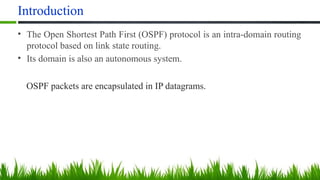
Introduction
• The OpenShortest Path First (OSPF) protocol is an intra-domain routing
protocol based on link state routing.
• Its domain is also an autonomous system.
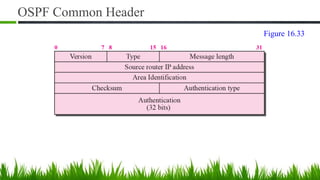
OSPF packets are encapsulated in IP datagrams.
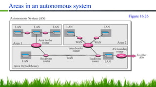
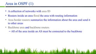
Area in OSPF(1)
• A collection of networks with area ID
• Routers inside an area flood the area with routing information
• Area border routers summarize the information about the area and send it
to other areas
• Backbone area and backbone routers
– All of the area inside an AS must be connected to the backbone
47.
Area in OSPF(2)
• Virtual link
– If, because of some problem, the connectivity between a backbone
and an area is broken, a virtual link between routers must be created
by the administration to allow continuity of the functions of the
backbone as the primary area
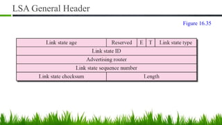
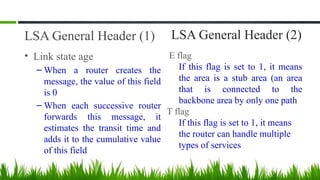
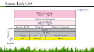
LSA General Header(1)
• Link state age
– When a router creates the
message, the value of this field
is 0
– When each successive router
forwards this message, it
estimates the transit time and
adds it to the cumulative value
of this field
LSA General Header (2)
E flag
If this flag is set to 1, it means
the area is a stub area (an area
that is connected to the
backbone area by only one path
T flag
If this flag is set to 1, it means
the router can handle multiple
types of services
58.
LSA General Header(3)
• Advertising router
– The IP address of the router advertising this message
• Link state sequence number
– A sequence number assigned to each link state update message
59.
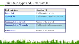
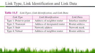
Link State Typeand Link State ID
Link state type Link state ID
Router link IP address of the router
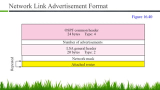
Network link IP address of the designated router
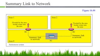
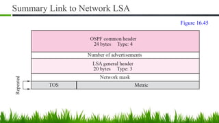
Summary link to network Address of the network
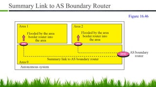
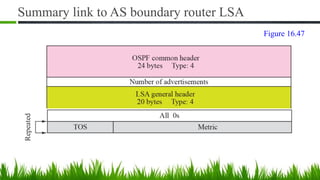
Summary link to AS boundary IP address of the boundary router
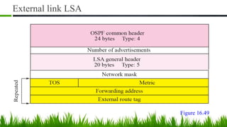
External link Address of the network
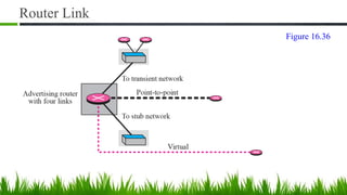
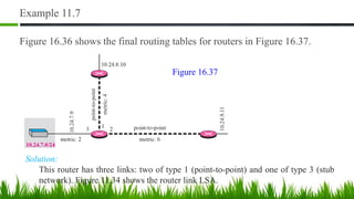
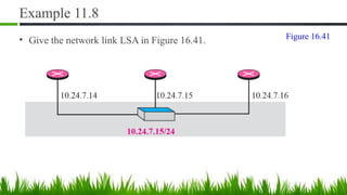
Example 11.7
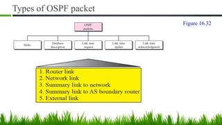
Figure 16.36shows the final routing tables for routers in Figure 16.37.
Solution:
This router has three links: two of type 1 (point-to-point) and one of type 3 (stub
network). Figure 11.34 shows the router link LSA.
Figure 16.37
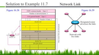
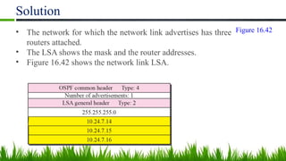
Solution
• The networkfor which the network link advertises has three
routers attached.
• The LSA shows the mask and the router addresses.
• Figure 16.42 shows the network link LSA.
Figure 16.42
68.
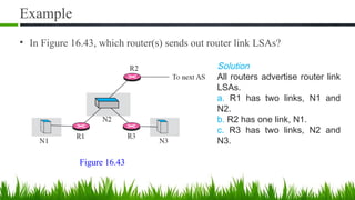
Example
• In Figure16.43, which router(s) sends out router link LSAs?
Solution
All routers advertise router link
LSAs.
a. R1 has two links, N1 and
N2.
b. R2 has one link, N1.
c. R3 has two links, N2 and
N3.
Figure 16.43
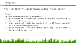
69.
Example
• In Figure16.43, which router(s) sends out the network link LSAs?
Solution
All three networks must advertise network links:
a) Advertisement for N1 is done by R1 because it is the only attached router and
therefore the designated router.
b) Advertisement for N2 can be done by either R1, R2, or R3, depending on which
one is chosen as the designated router.
c) Advertisement for N3 is done by R3 because it is the only attached router and
therefore the designated router
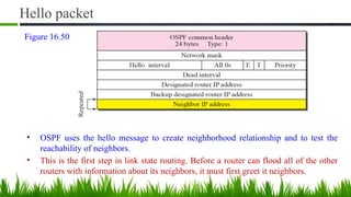
Hello packet
• OSPFuses the hello message to create neighborhood relationship and to test the
reachability of neighbors.
• This is the first step in link state routing. Before a router can flood all of the other
routers with information about its neighbors, it must first greet it neighbors.
Figure 16.50
77.
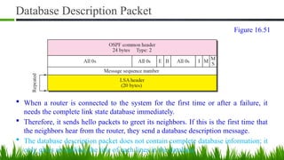
Database Description Packet
When a router is connected to the system for the first time or after a failure, it
needs the complete link state database immediately.
Therefore, it sends hello packets to greet its neighbors. If this is the first time that
the neighbors hear from the router, they send a database description message.
The database description packet does not contain complete database information; it
only gives an outline, the title of each lines in the database.
Figure 16.51