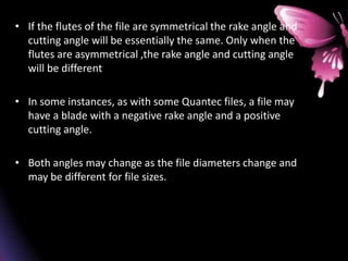
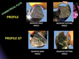
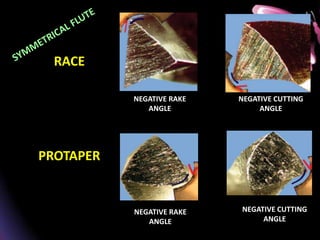
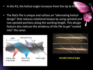
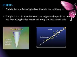
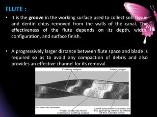
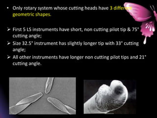
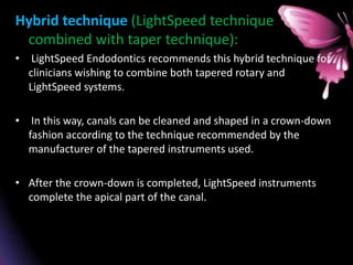
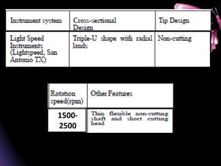
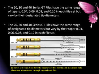
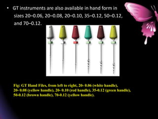
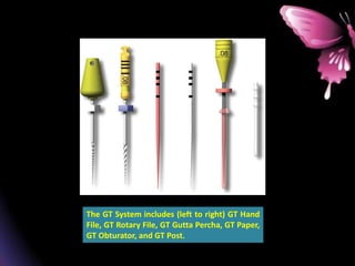
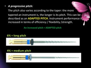
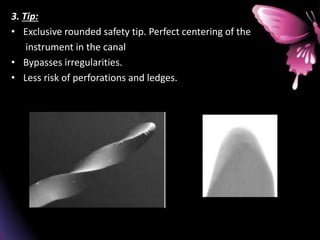
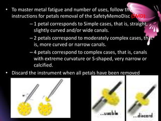
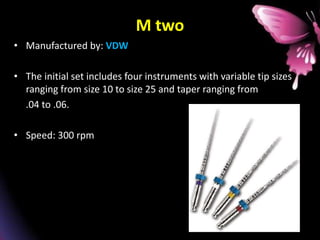
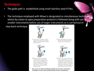
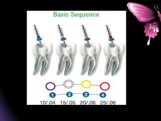
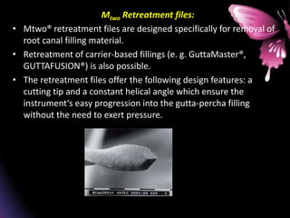
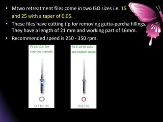
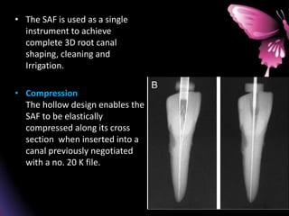
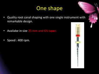
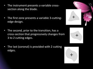
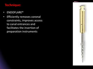
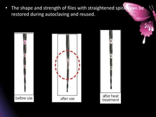
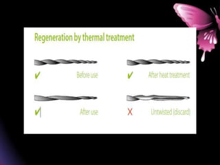
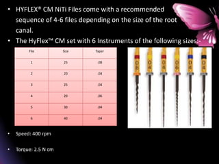
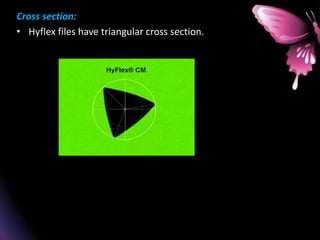
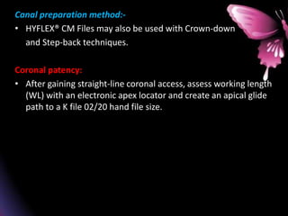
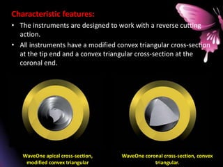
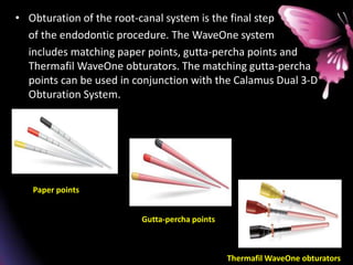
This document provides a summary of rotary instruments used in endodontics, focusing on nickel titanium (NiTi) instruments. It discusses the history and development of rotary instruments, the properties of NiTi alloy, components and design features of rotary files, and several rotary systems including LightSpeed. Key points include: NiTi files provide improved flexibility and shapeability compared to stainless steel; components include the tip, taper, rake angle, radial lands, and flutes; and systems like LightSpeed are taperless with short cutting heads for improved negotiation of curvatures.

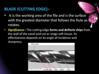
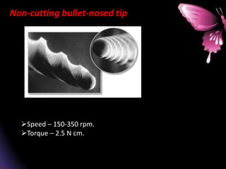
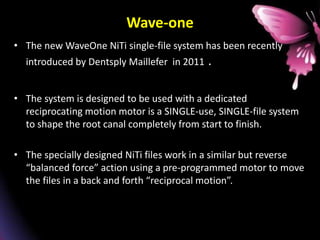
![Nickel titanium [NiTi] Endodontic instruments
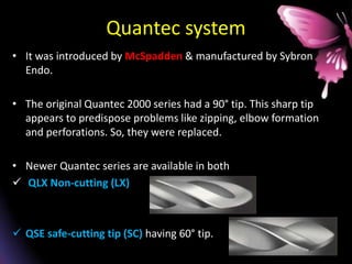
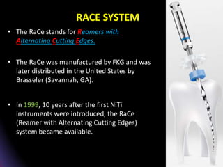
• When using the stainless steel files, occurrence of procedural
errors cannot be avoided specially in case of curved canals.
Deviation from the original shape, ledge formation, zipping,
stripping and perforations are common problems which are seen
in such cases.
• But the superelasticity of NiTi alloy allows these instruments to
flex more than the stainless steel instruments before exceeding
their elastic limit, thereby allowing canal preparation with
minimal procedural errors.](https://image.slidesharecdn.com/12-240115183229-5e4b19ce/85/12-ROTARY-INSTRUMENTS-IN-ENDODONTICS-pptx-8-320.jpg)
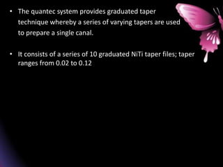
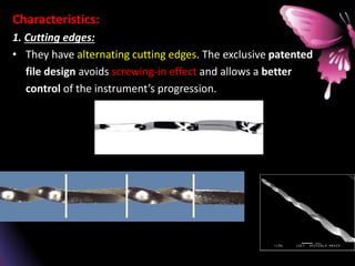
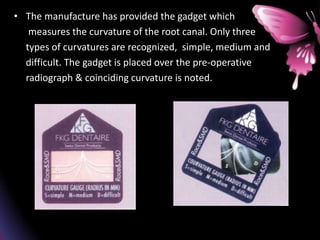
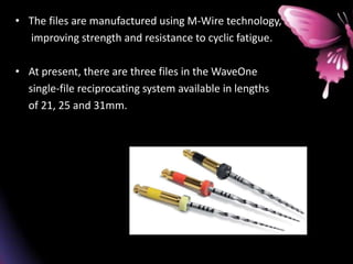
![• NiTi was developed by Buchler 40 year ago. NiTi is
also known NiTinol [NiTi Naval ordinance laboratory
in US].
• In endodontics commonly used NiTi alloys are called
55 NiTi nol[55% wt Ni and 45% Ti] and 60 NiTi nol
[60% wt of Ni, 40% Ti].](https://image.slidesharecdn.com/12-240115183229-5e4b19ce/85/12-ROTARY-INSTRUMENTS-IN-ENDODONTICS-pptx-9-320.jpg)
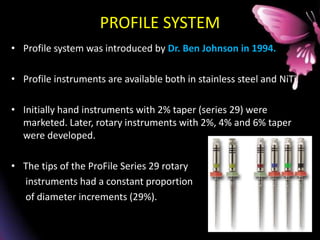
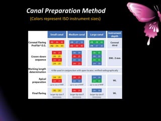
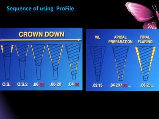
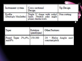
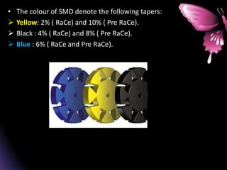
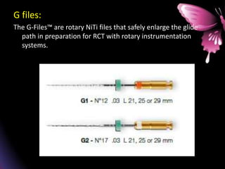
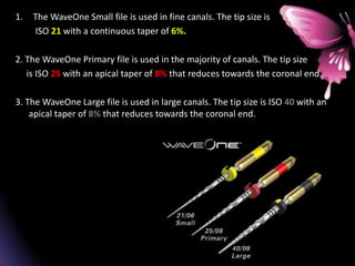
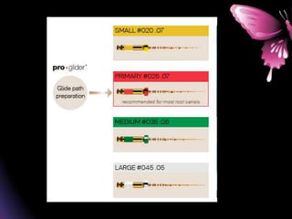
![Later on profile series with ISO-sized tips and orifice
shaper were also marketed.
I] Series 29
a) Hand instruments -0.02 taper.
b) Rotary instruments -0.04, 0.06 taper.
II] ISO Series
a) 0.04 and 0.06 taper hand and rotary instruments.
Ⅲ] Profile Orifice shaper: 0.05- 0.08 taper.
IV] Profile GT rotary instruments AND hand files](https://image.slidesharecdn.com/12-240115183229-5e4b19ce/85/12-ROTARY-INSTRUMENTS-IN-ENDODONTICS-pptx-59-320.jpg)


![ONFH[AVN HIP] -TRIPLE REGIME -A NOVAL SURGICAL CONCEPT .pptx](https://cdn.slidesharecdn.com/ss_thumbnails/onfhavnhip2026koaconcalicutdrgokuldevdrmashraf-260210064517-213ec005-thumbnail.jpg?width=640&height=640&fit=bounds)


