Introduction
Stainless steelinstruments have a natural tendency to
straighten curved canals due to its inherent stiffness and
as it could not follow curvatures even in moderately
curved canals. They had thus to be precurved to reach
length, which in turn forced operators to use them
exclusively in filing motion.
This resulted in a high incidence of procedural errors,
such as ledges, elbows, zipping, strippings, and
perforations.
4.
In 1960a novel nickel-titanium alloy was developed by
William Buehler in Silver Springs, Maryland at the United
States Naval Ordinance Laboratory -NITINOL where
NOL stands for Naval Ordnance Laboratory).
In 1988, Dr. Harmeet D. Walia et al proposed Nitinol
for shaping canals, as it is 2 to 3 times more flexible, in
the same file sizes, compared to stainless steel.
5.
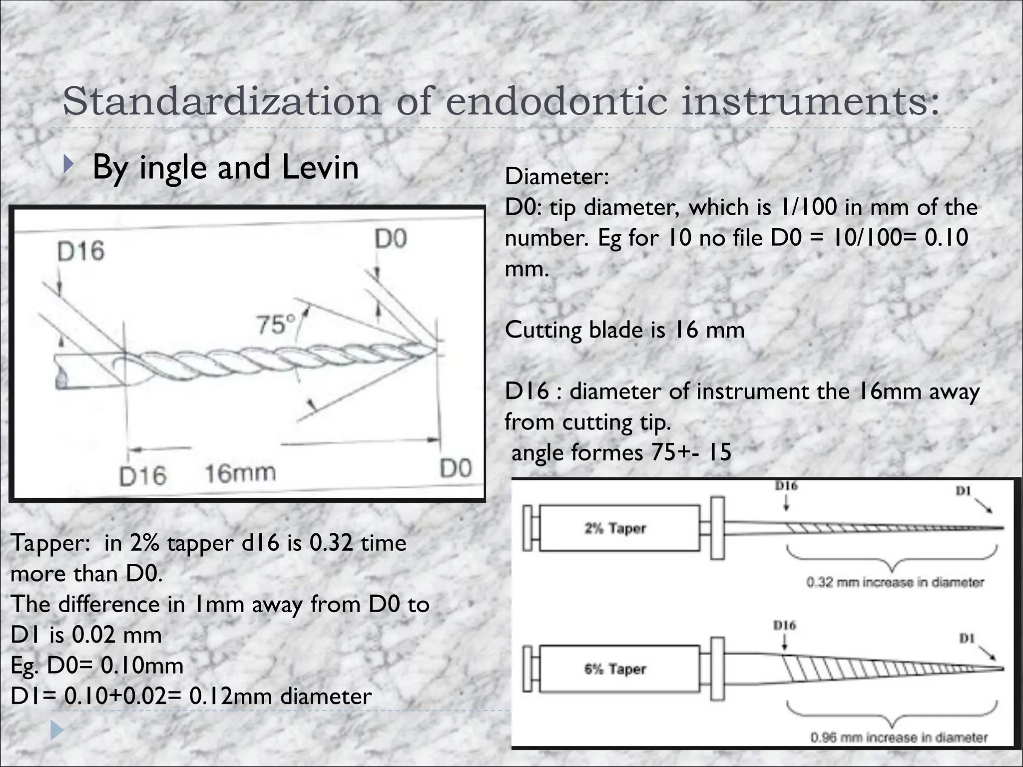
Standardization of endodonticinstruments:
By ingle and Levin Diameter:
D0: tip diameter, which is 1/100 in mm of the
number. Eg for 10 no file D0 = 10/100= 0.10
mm.
Cutting blade is 16 mm
D16 : diameter of instrument the 16mm away
from cutting tip.
angle formes 75+- 15
Tapper: in 2% tapper d16 is 0.32 time
more than D0.
The difference in 1mm away from D0 to
D1 is 0.02 mm
Eg. D0= 0.10mm
D1= 0.10+0.02= 0.12mm diameter
6.
GENERATIONS OF ROTARYSYSTEMS
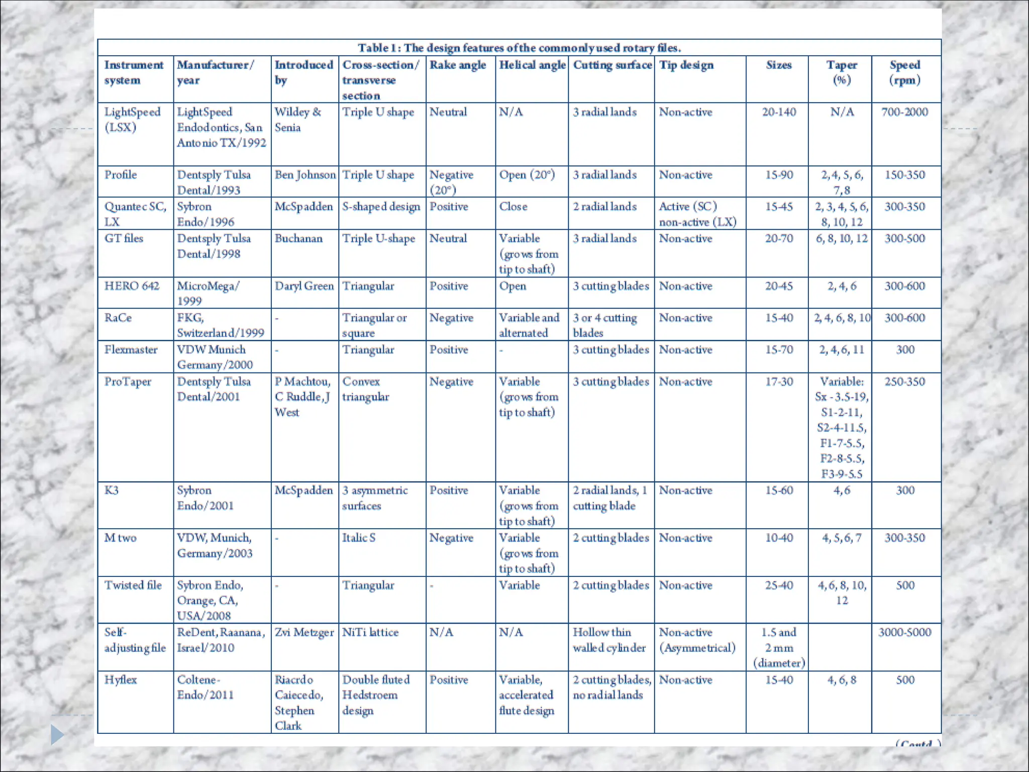
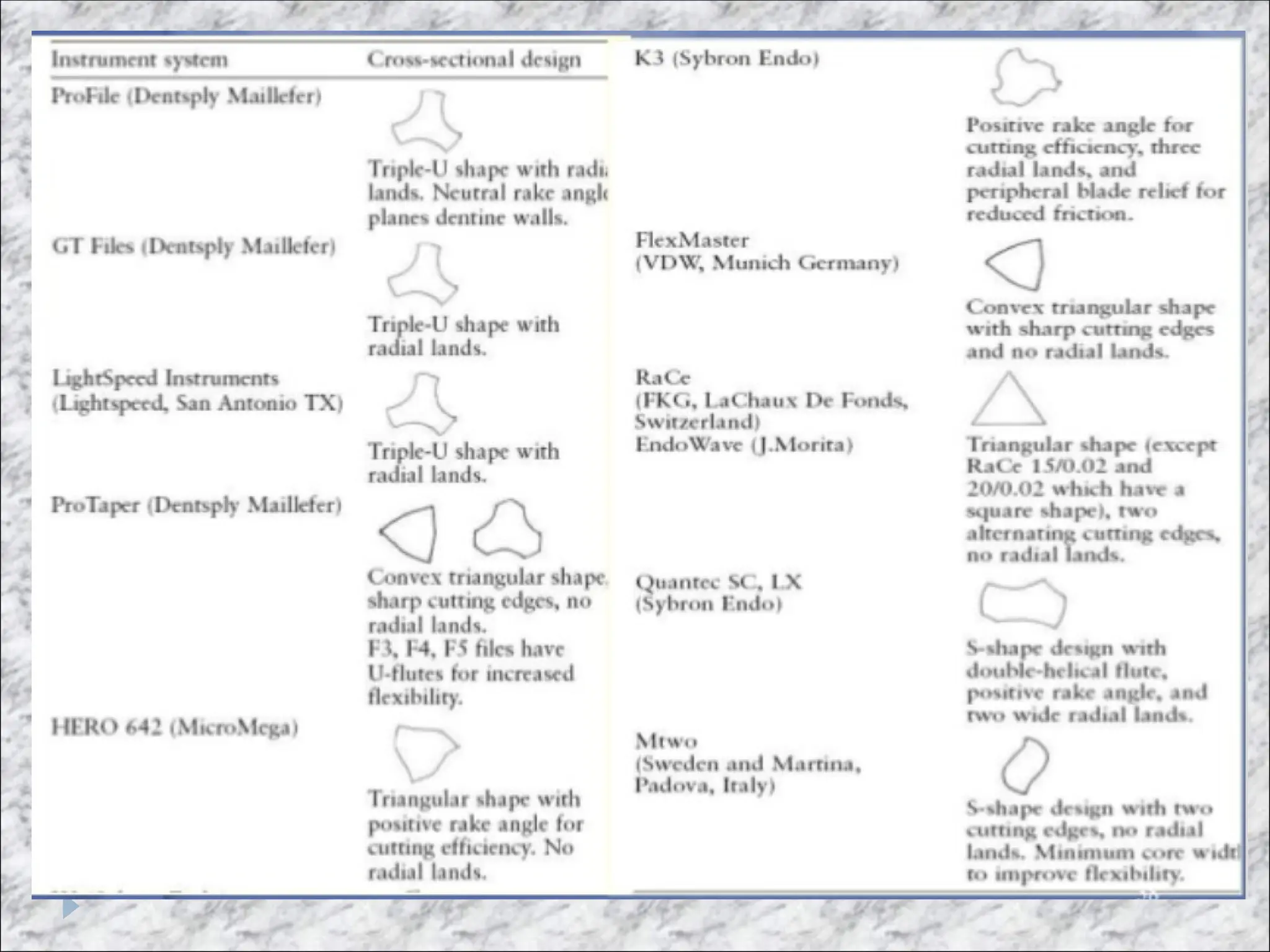
First generation niti files
They have passive cutting radial lands and fixed tapers of 4% and
6% over the length of their active blades
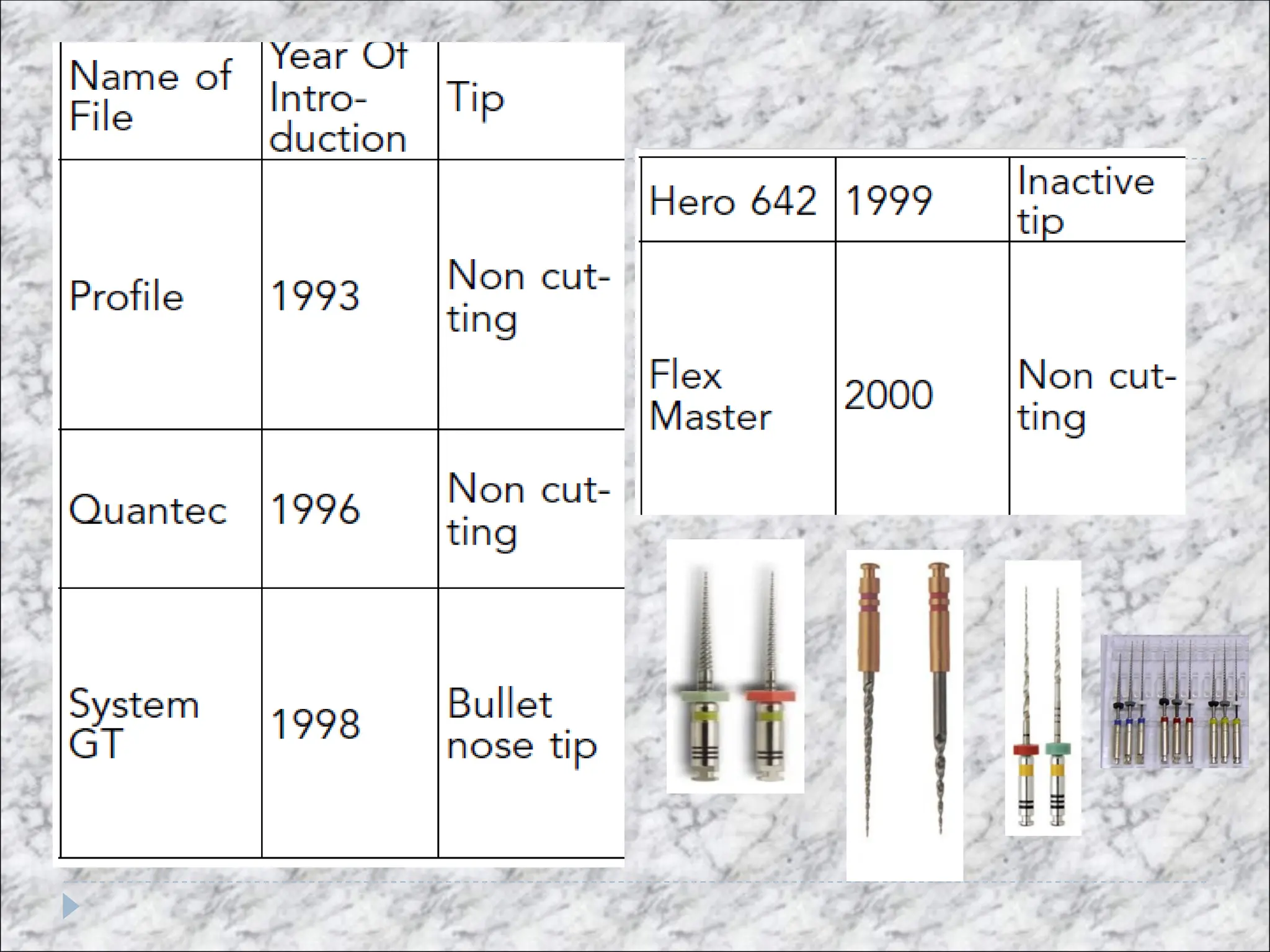
This generation of technology required numerous files to
achieve the preparation objectives. By the mid to late 1990s,
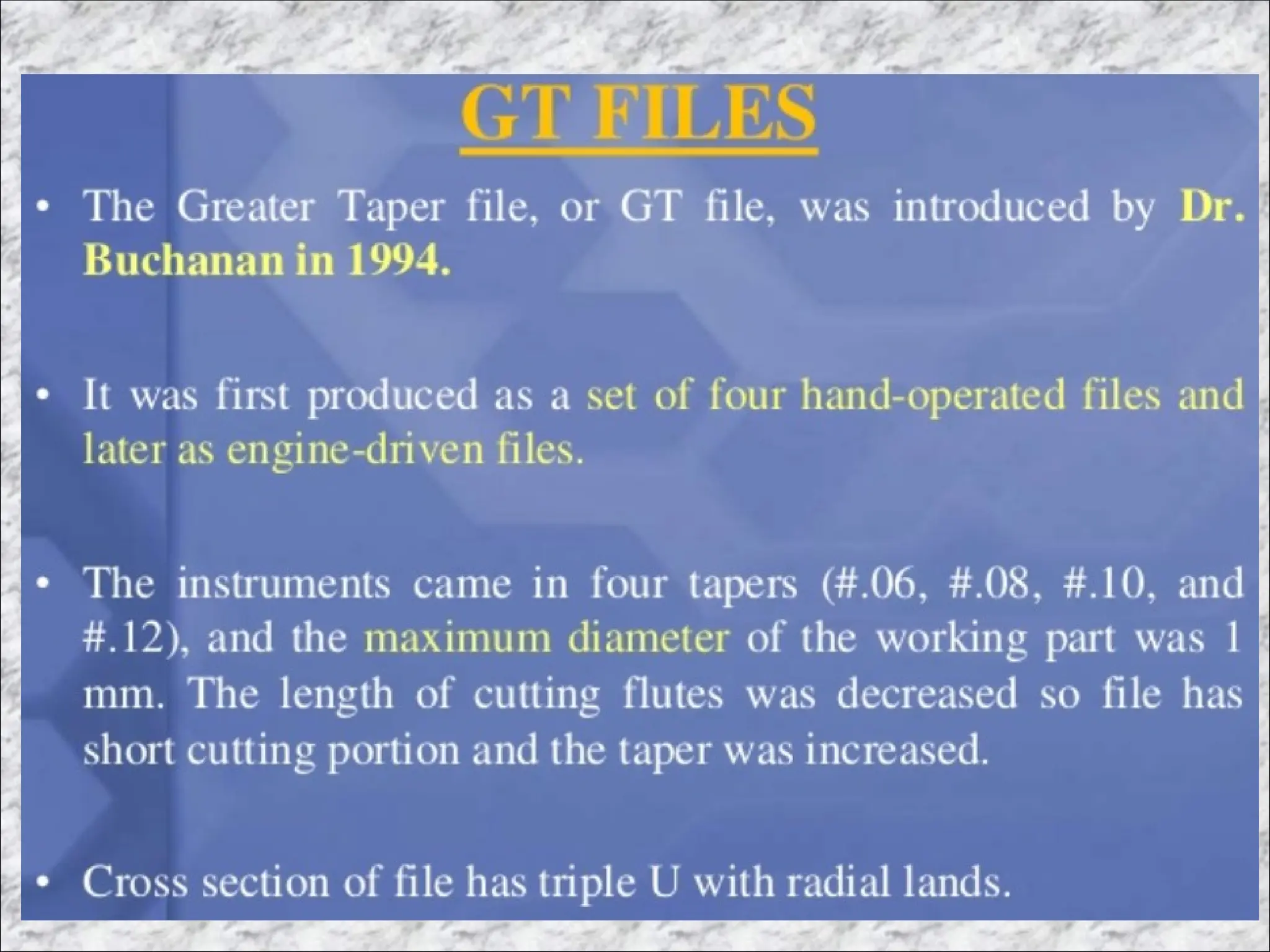
GT files (Dentsply Tulsa Dental Specialties) became available that
provided a fixed taper on a single file of 6%, 8%, 10%, and 12%.
The single most important design feature of first generation
NiTi rotary file was passive radial lands, which encouraged
a file to stay centered in canal curvatures during work.
8.
second generation
Thisgeneration of NiTi rotary files came to market in 2001
The critical distinction of this generation of instruments is
they have active cutting edges and require fewer instruments to
fully prepare a canal.
Alternating contact points were added to discourage the
taper lock and the resultant screw effect associated with
both passive and active fixed tapered NiTi cutting
instruments
9.
The clinical breakthroughoccurred when ProTaper (Dentsply
Tulsa Dental Specialties) came to market utilizing multiple
increasing or decreasing percentage tapers on a single file.
This revolutionary, progressively tapered design limits
each file’s cutting action to a specific region of
the canal and affords a shorter sequence of files to safely
produce deep Schilderian shapes
11.
THIRD GENERATION
Improvementsin NiTi metallurgy became the hallmark of
what may be identified as the 3rd generation of mechanical
shaping files. In 2007, manufacturers began to focus on
utilizing heating and cooling methods to reduce cyclic
fatigue and improve safety when rotary NiTi instruments
work in more curved canals.
This 3rd
generation of NiTi instruments significantly
reduces cyclic fatigue and, hence, broken files.
13.
FOURTH GENERATION
Anotheradvancement in canal preparation procedures
utilizes reciprocation, which may be defined as any repetitive
up-and-down or back-and-forth motion. This technology was
first introduced in the late 1950s by the French dentist,
Blanc.
innovation in reciprocation technology led to a 4th
generation of instruments for shaping canals. This generation
of instruments and related technology has largely fulfilled the
long hoped-for single-file technique. ReDent-Nova (Henry
Schein) introduced the Self Adjusting File (SAF
14.
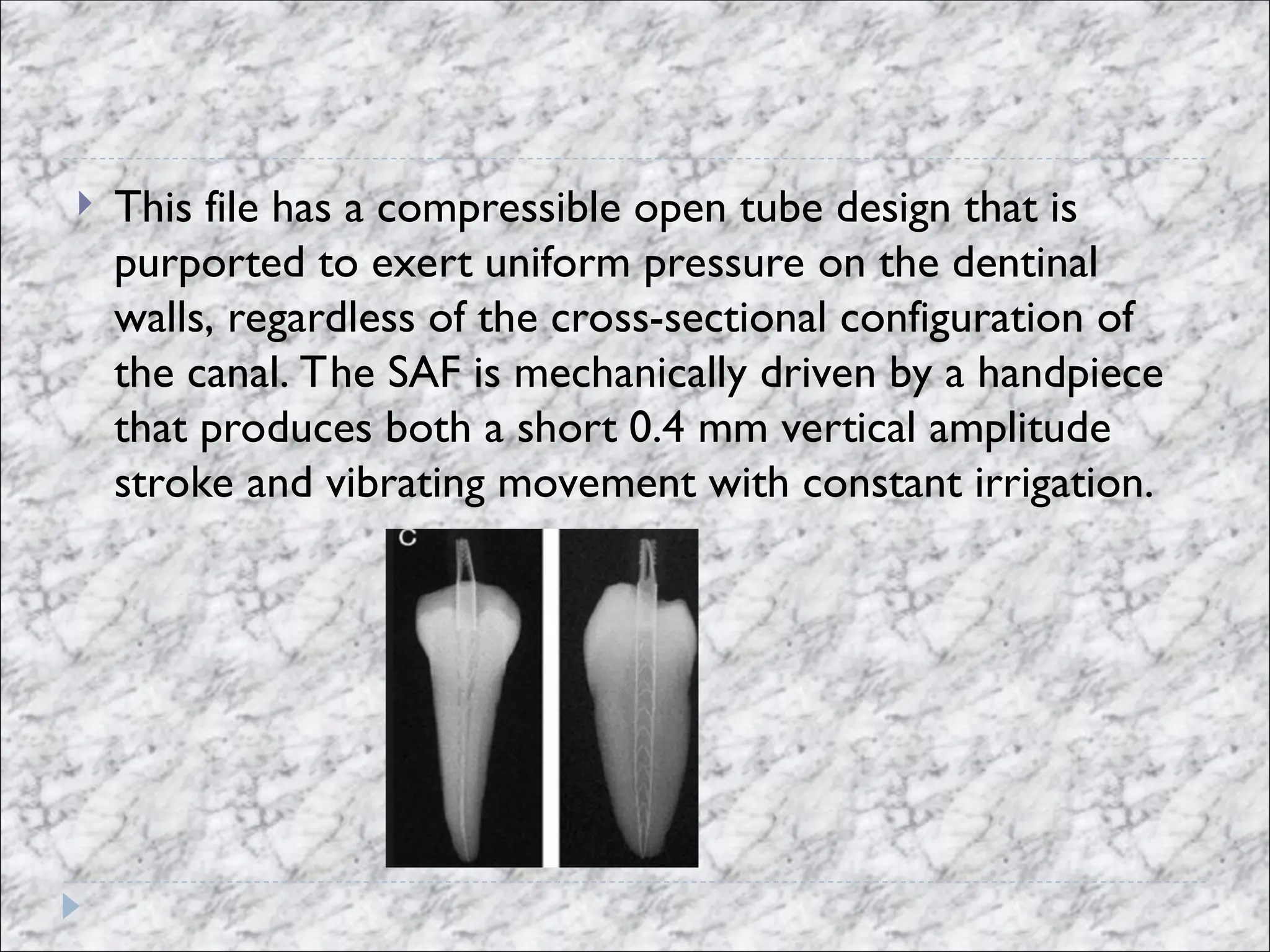
This filehas a compressible open tube design that is
purported to exert uniform pressure on the dentinal
walls, regardless of the cross-sectional configuration of
the canal. The SAF is mechanically driven by a handpiece
that produces both a short 0.4 mm vertical amplitude
stroke and vibrating movement with constant irrigation.
15.
FIFTH GENERATION
The5th generation of shaping files has been designed such
that the center of mass and/or the center of rotation are
offset. In rotation, files that have an offset design
produce a mechanical wave of motion that travels along the
active length of the file.
Like the progressively percentage
tapered design of any given ProTaper file, this offset design
serves to further minimize the engagement between the file
and dentin.
In addition, an offset design enhances augering
debris out of a canal and improves flexibility along the active
portion of a PTN file.
16.
Terminologies:
1. TIPDESIGN: there are 2 main functions of the
instruments: form a glide path and penetrate deeper into
the canal.
Studies have shown the tip design to affect the file control
and efficacy and outcome in shaping the root canal system.
Tip designs are classsified as :
1. cutting tip.
2. non cutting tips. ( batt tips)
3. Partially cutting tips
17.
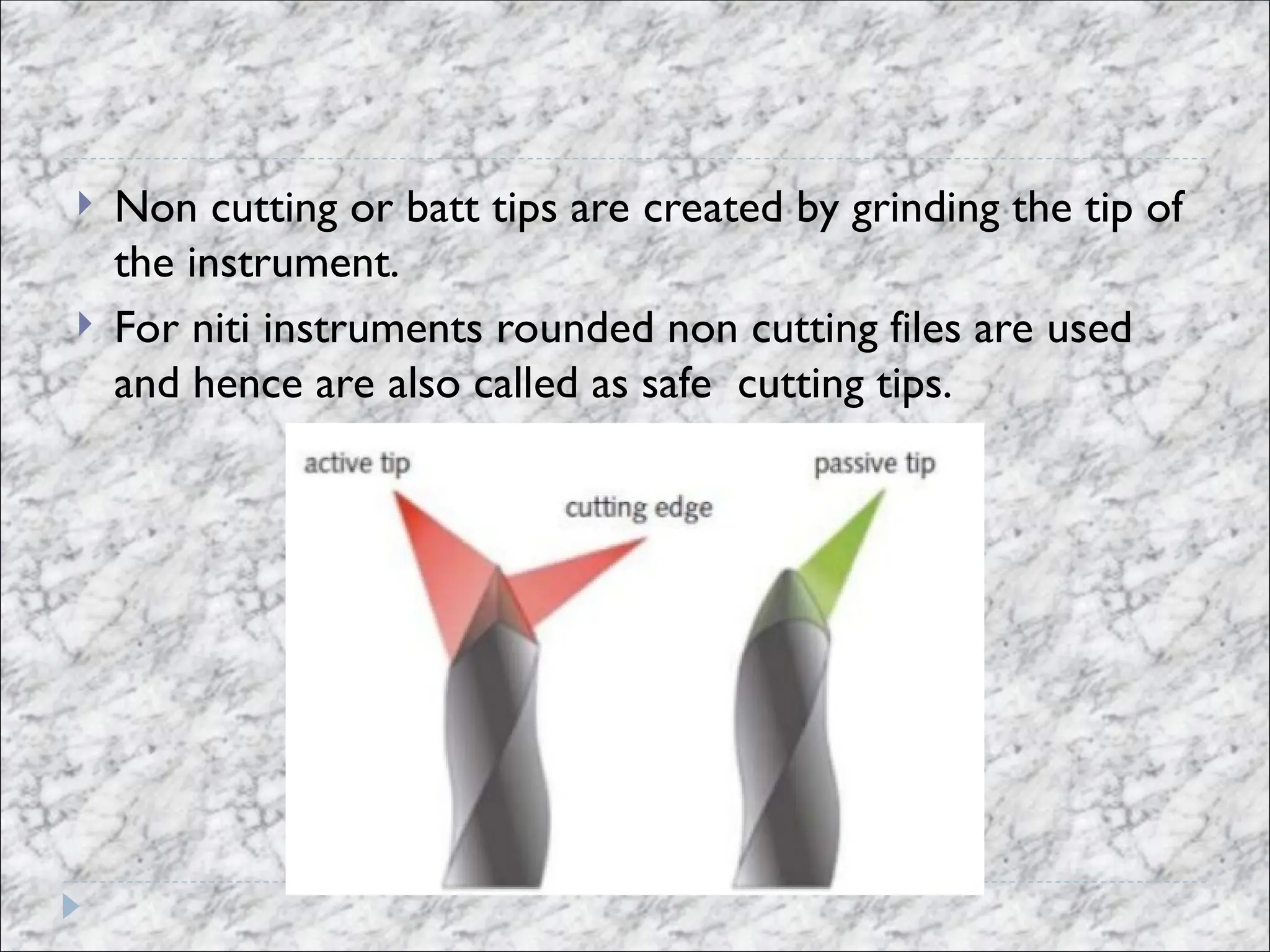
Non cuttingor batt tips are created by grinding the tip of
the instrument.
For niti instruments rounded non cutting files are used
and hence are also called as safe cutting tips.
18.
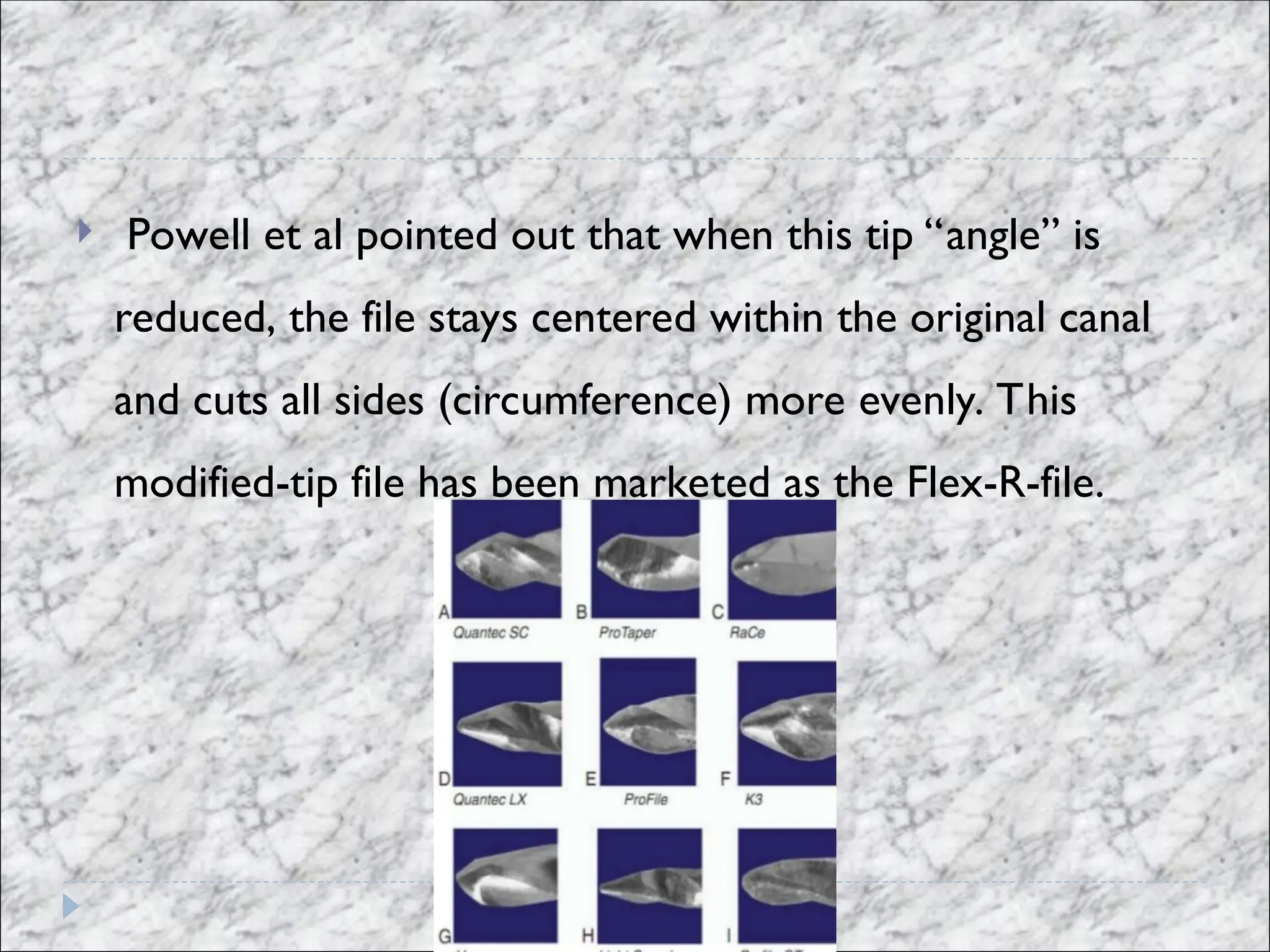
Powell etal pointed out that when this tip “angle” is
reduced, the file stays centered within the original canal
and cuts all sides (circumference) more evenly. This
modified-tip file has been marketed as the Flex-R-file.
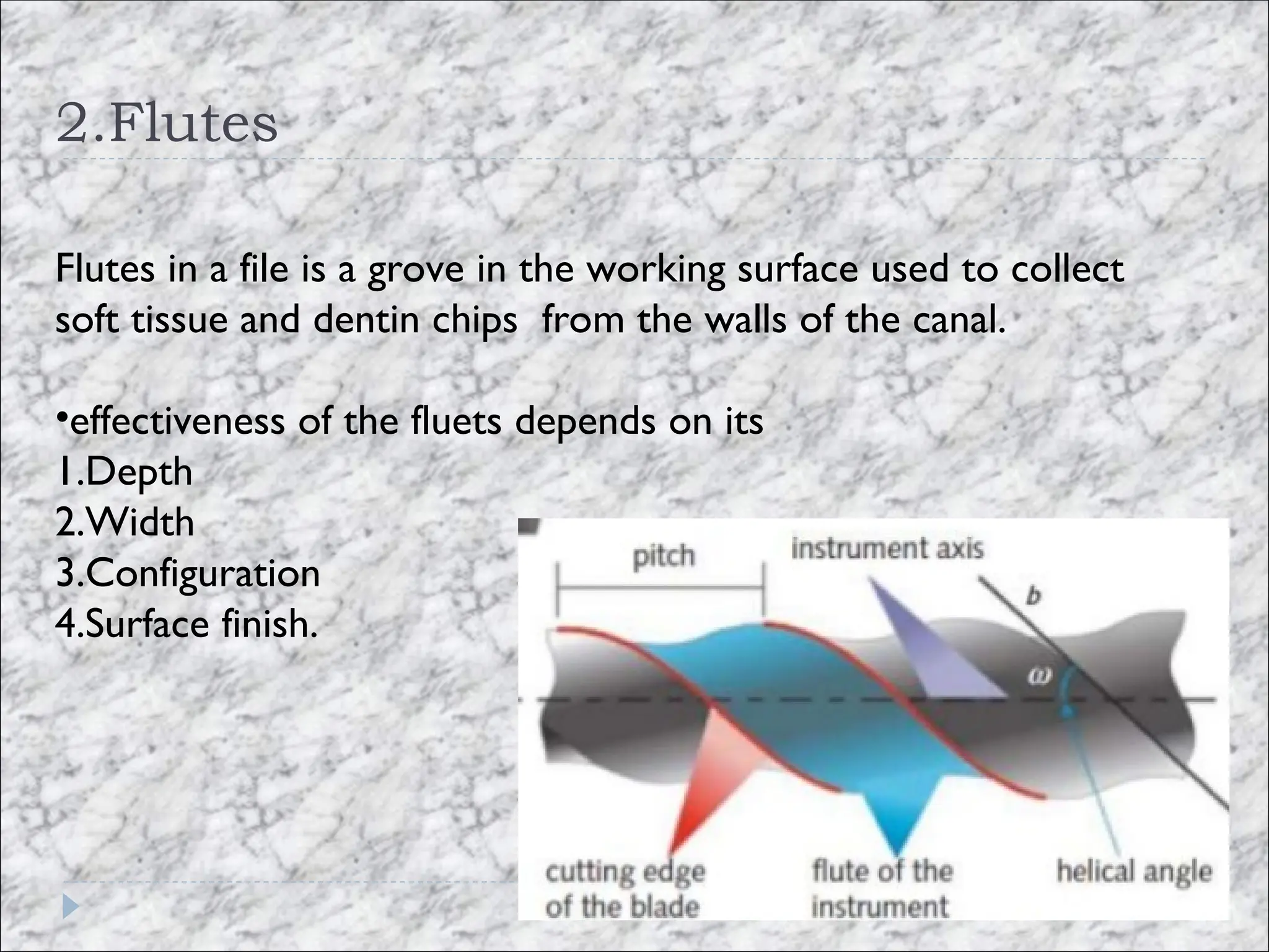
2.Flutes
Flutes in afile is a grove in the working surface used to collect
soft tissue and dentin chips from the walls of the canal.
•effectiveness of the fluets depends on its
1.Depth
2.Width
3.Configuration
4.Surface finish.
21.
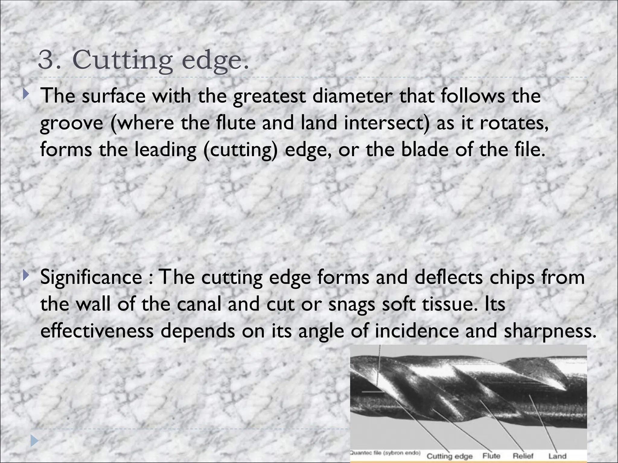
3. Cutting edge.
The surface with the greatest diameter that follows the
groove (where the flute and land intersect) as it rotates,
forms the leading (cutting) edge, or the blade of the file.
Significance : The cutting edge forms and deflects chips from
the wall of the canal and cut or snags soft tissue. Its
effectiveness depends on its angle of incidence and sharpness.
22.
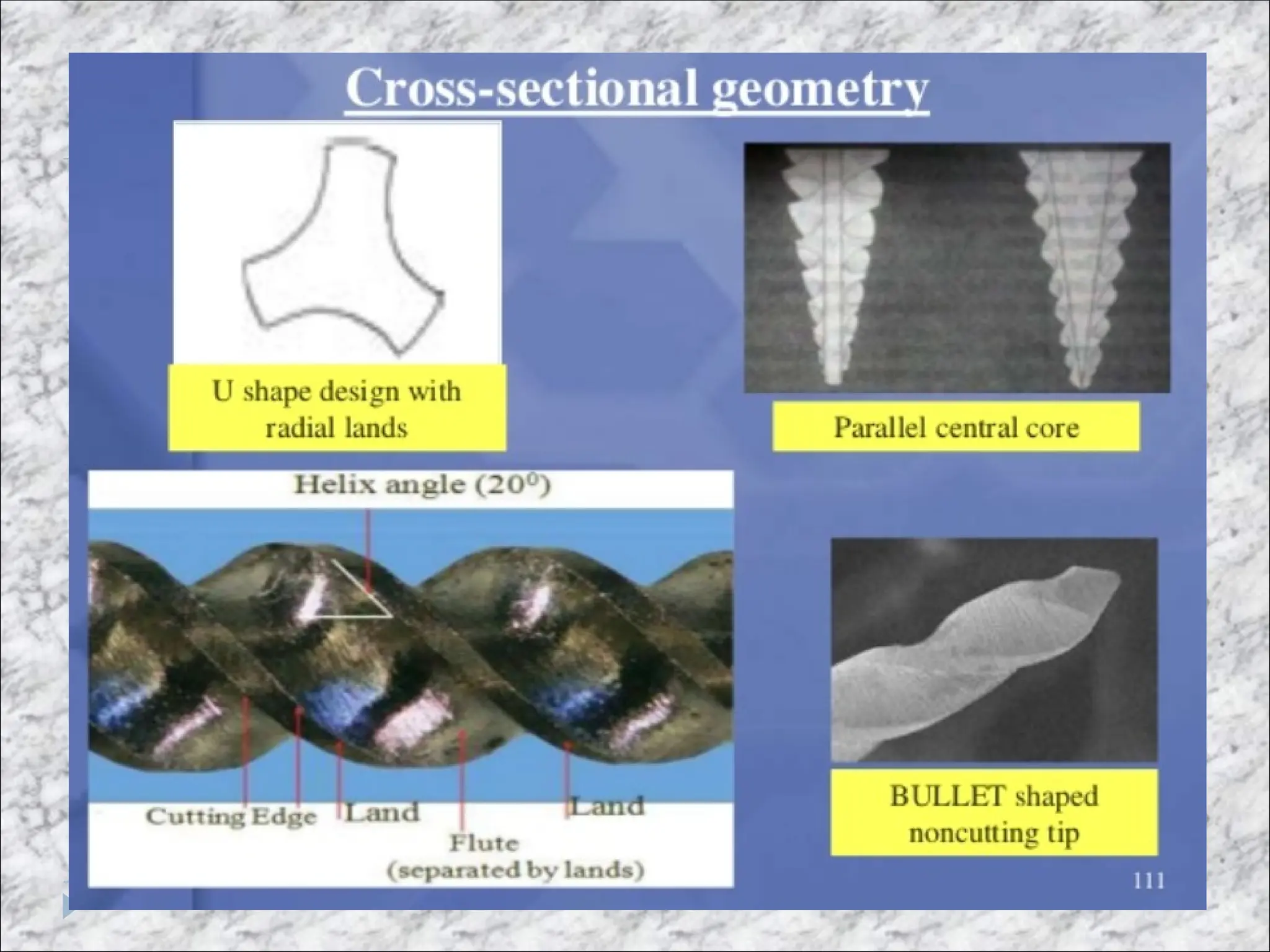
4. Radial land
Some instruments have a feature between trailing and cutting
edge that forms a larger contact area with thw radicular wall
this surface is known as radial land.
Such a land is thought to reduce the tendency of the file to
thread into the canal. it also supports the cutting edge and
limits the dept of cut and it s width determines its
effectiveness.
On the other hand landed files are typically less cutting
compaied to triangular files
23.
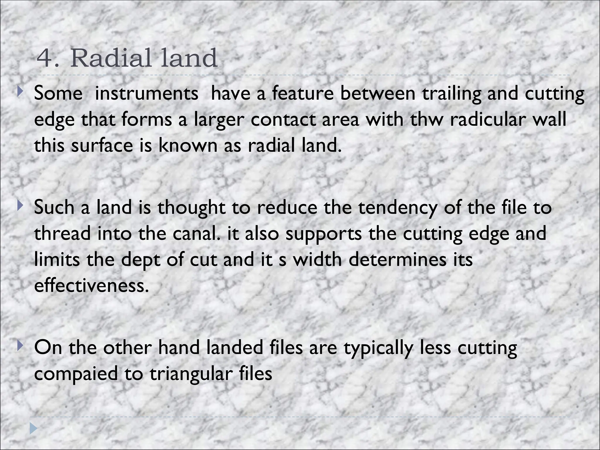
Functions ofland
• Prevents ‘‘screwing in’’ of the file
• Supports the cutting edge
• Limits the depth of cut
• Reduces the propagation of microcracks on its circumference.
• Maintains the file in the centre of root canal
To reduce the frictional resistance ,some of the surface area of
the land that rotates against the canal wall amy be reduced to
form a relief.
24.
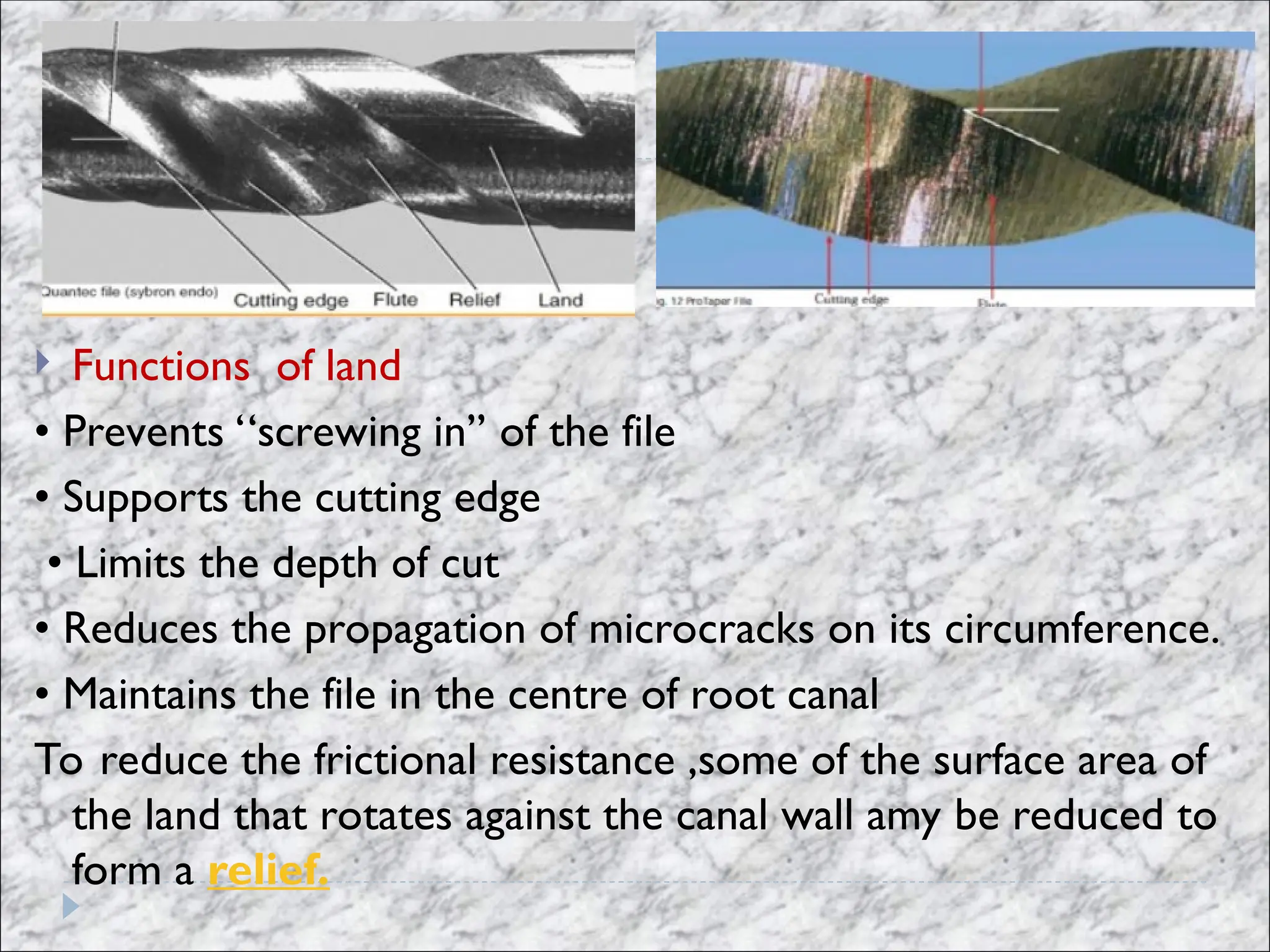
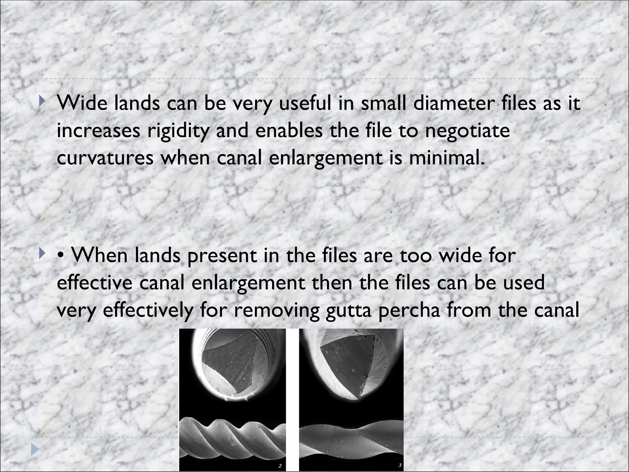
Wide landscan be very useful in small diameter files as it
increases rigidity and enables the file to negotiate
curvatures when canal enlargement is minimal.
• When lands present in the files are too wide for
effective canal enlargement then the files can be used
very effectively for removing gutta percha from the canal
26.
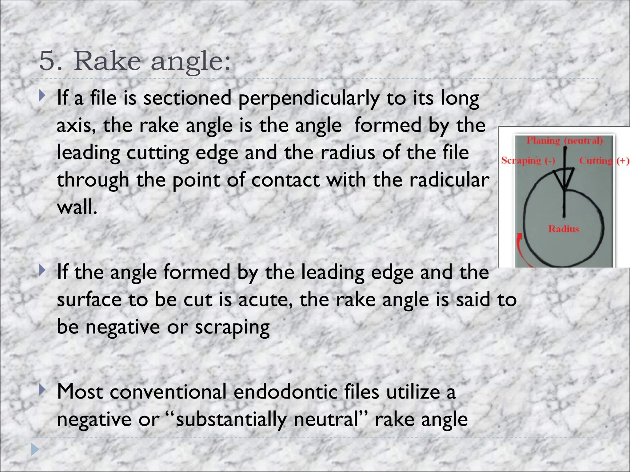
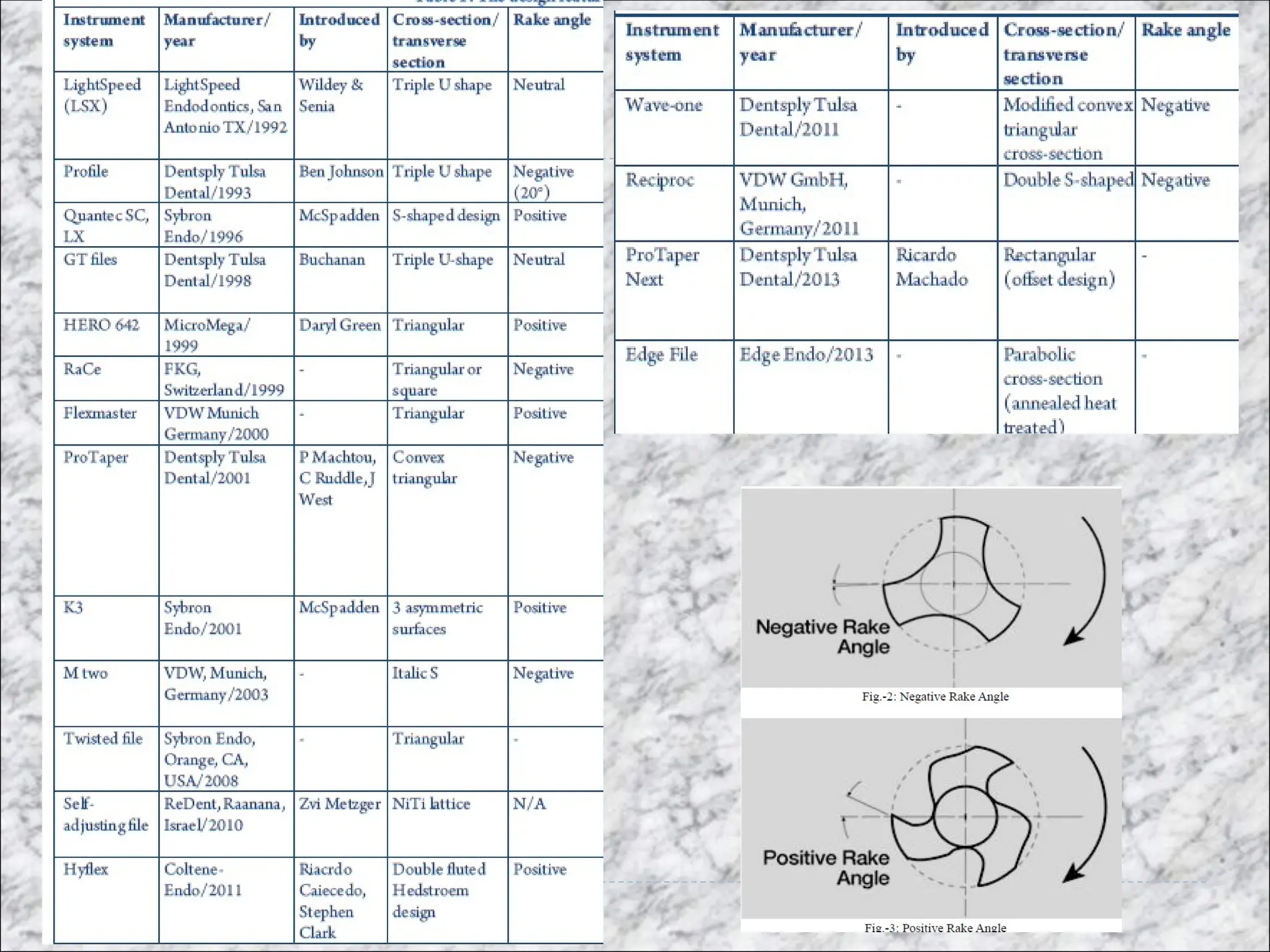
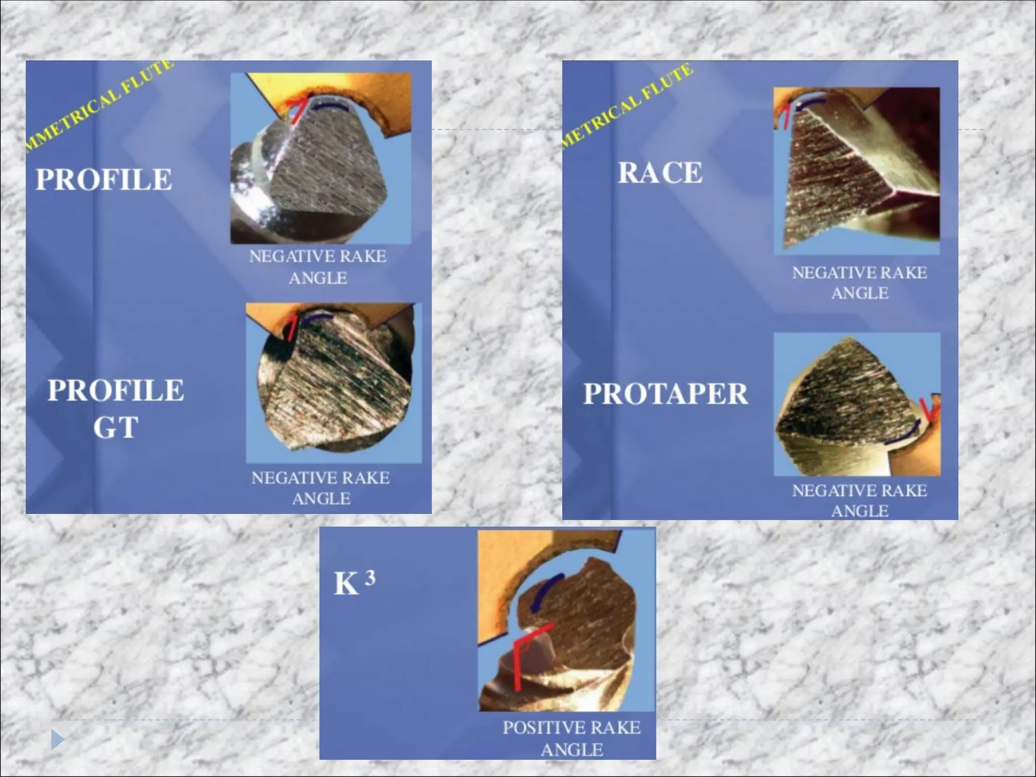
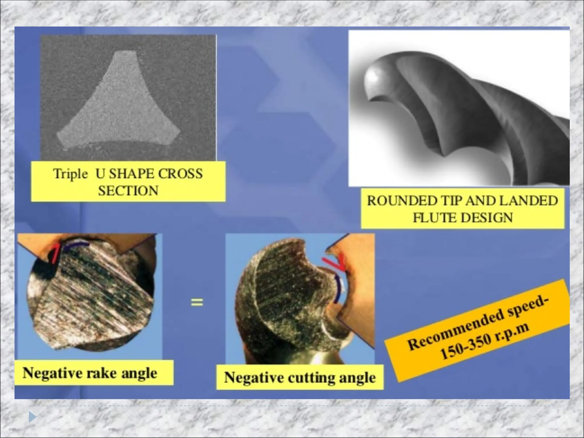
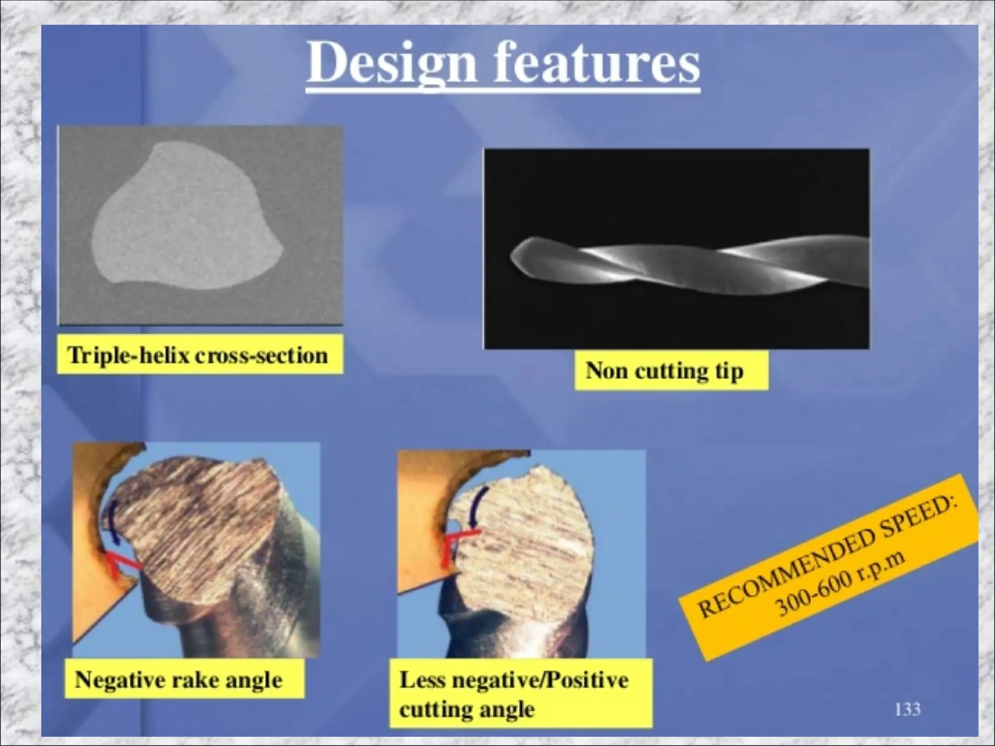
5. Rake angle:
If a file is sectioned perpendicularly to its long
axis, the rake angle is the angle formed by the
leading cutting edge and the radius of the file
through the point of contact with the radicular
wall.
If the angle formed by the leading edge and the
surface to be cut is acute, the rake angle is said to
be negative or scraping
Most conventional endodontic files utilize a
negative or “substantially neutral” rake angle
27.
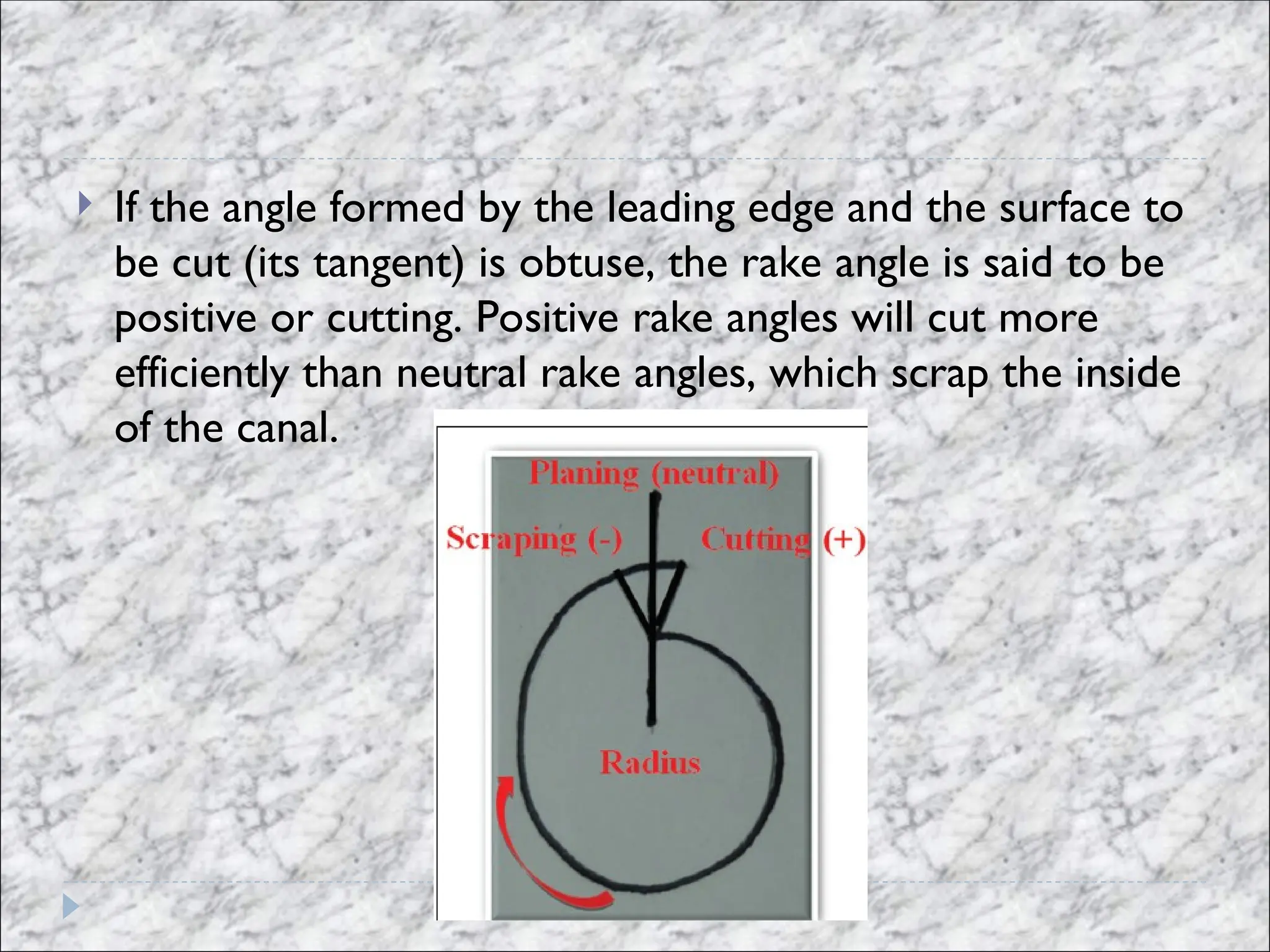
If theangle formed by the leading edge and the surface to
be cut (its tangent) is obtuse, the rake angle is said to be
positive or cutting. Positive rake angles will cut more
efficiently than neutral rake angles, which scrap the inside
of the canal.
28.
However rakeangle may not be same as the cutting
angle.
The cutting angle or effective rake angle is a better
indication of the cutting ability of a file and is obtained by
measuring the angle formed by the cutting (leading) edge
and the radius when the file is sectioned perpendicular to
its cutting edge.
31.
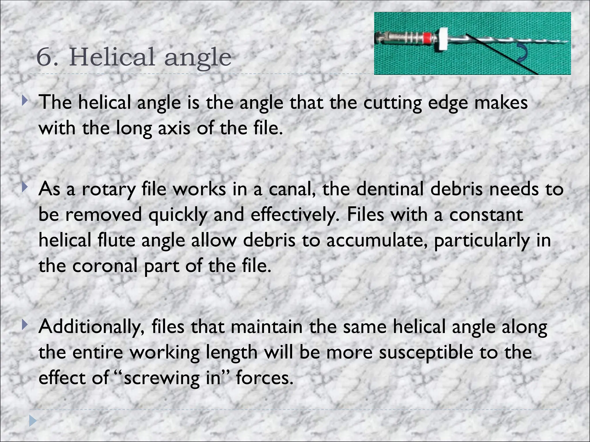
6. Helical angle
The helical angle is the angle that the cutting edge makes
with the long axis of the file.
As a rotary file works in a canal, the dentinal debris needs to
be removed quickly and effectively. Files with a constant
helical flute angle allow debris to accumulate, particularly in
the coronal part of the file.
Additionally, files that maintain the same helical angle along
the entire working length will be more susceptible to the
effect of “screwing in” forces.
32.
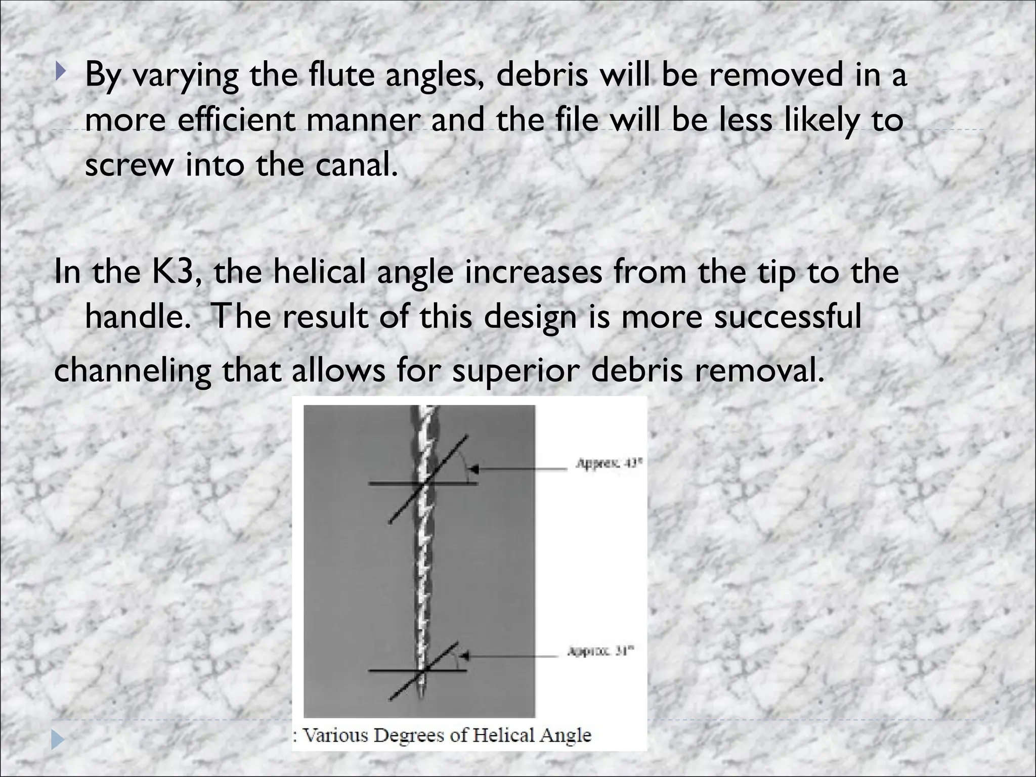
By varyingthe flute angles, debris will be removed in a
more efficient manner and the file will be less likely to
screw into the canal.
In the K3, the helical angle increases from the tip to the
handle. The result of this design is more successful
channeling that allows for superior debris removal.
33.
The RaCe fileis unique and utilizes an “alternating helical
design” that reduces rotational torque by using spiraled
and non spiraled portions along the working length. This
design feature also reduces the tendency of the file to get
“sucked into” the canal.
34.
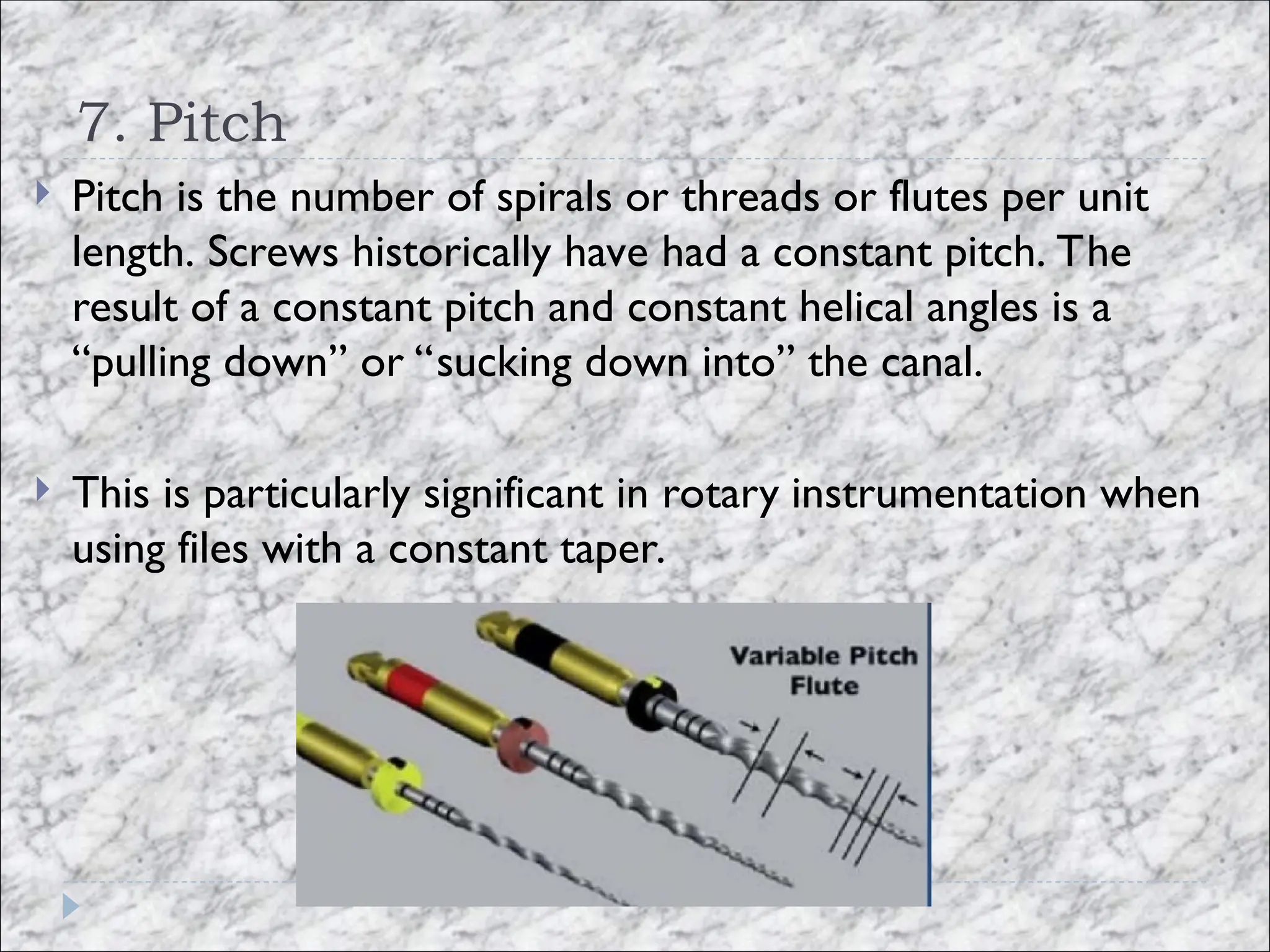
7. Pitch
Pitchis the number of spirals or threads or flutes per unit
length. Screws historically have had a constant pitch. The
result of a constant pitch and constant helical angles is a
“pulling down” or “sucking down into” the canal.
This is particularly significant in rotary instrumentation when
using files with a constant taper.
35.
K3 file hasbeen designed with constant tapers, but with
variable pitch and helical angles. The result is a dramatic
reduction in the sense of being “sucked down into” the
canal.
ProTaper has continuously changing pitch and helical
angle which reduces the screwing effect.
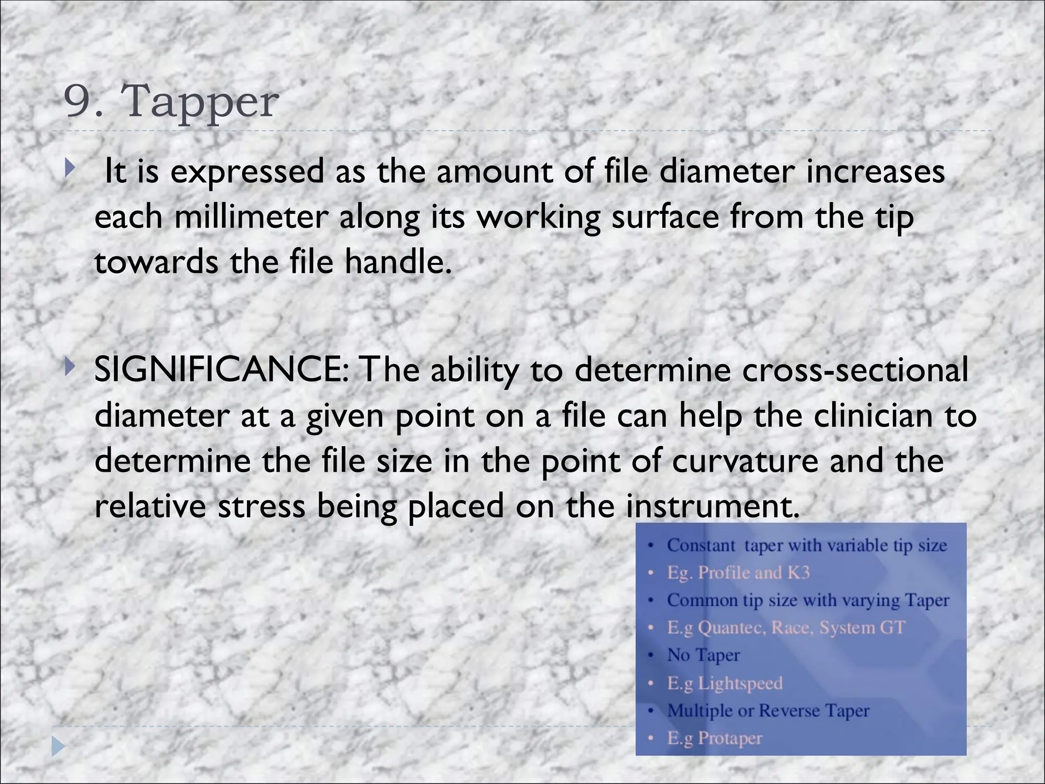
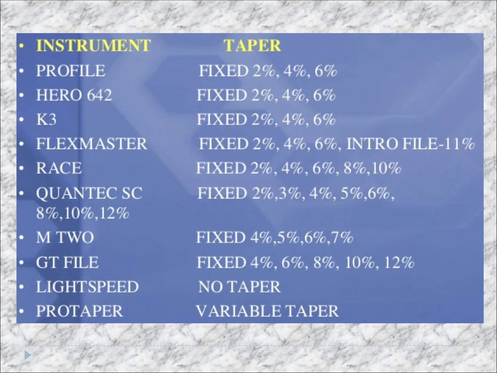
9. Tapper
Itis expressed as the amount of file diameter increases
each millimeter along its working surface from the tip
towards the file handle.
SIGNIFICANCE: The ability to determine cross-sectional
diameter at a given point on a file can help the clinician to
determine the file size in the point of curvature and the
relative stress being placed on the instrument.
40.
The Ieach successive file is only engaging a minimal
aspect of the canal wall. Therefore, frictional resistance is
reduced and requires less torque to properly run the file.
The popular GT Series of files consist of three different
instrument sequences, GT20, GT30 and GT40, according
to ISO size and employs a varying taper (10%, 8%, 6%,
4%) while the Quantec files use a graduated increase in
taperdea behind variable or graduating tapers is that
41.
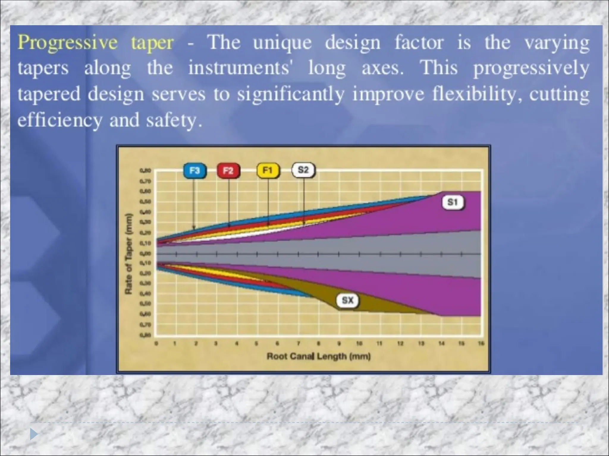
The ProtaperSystem features a progressive taper along its
shank. One of the benefits of such a design, according to
the manufacturer, is reduced torsional loading16
42.
conclusion
The combinationof the use of contemporary available modern
devices and files with a solid base of anatomical and biological
knowledge will lead to a predictably higher quality of root
canal treatment, thus helping to preserve the patient’s
dentition for several years. At the same time, it is apt to
remember that perfection ultimately depends more on the
operator than the instruments. Instruments cannot, at any
time, replace the nimble and skillful fingers of an endodontist.
-ve RAKEANGLE
Recommended speed: 150-300 rpm- Cleaning & shaping.
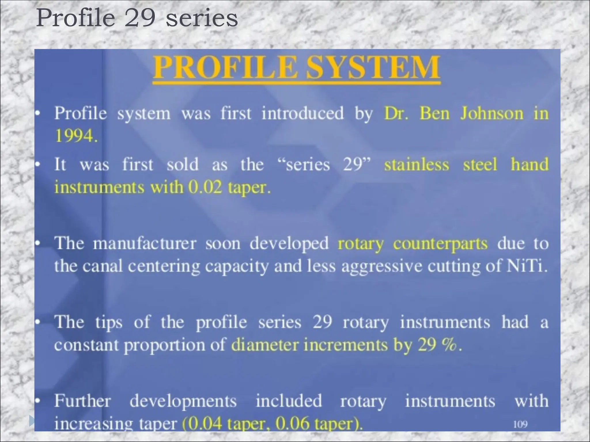
Series 29
The rate of increment between file sizes in this series is
constant i.e. 29%. • length - 21mm, 25mm
50.
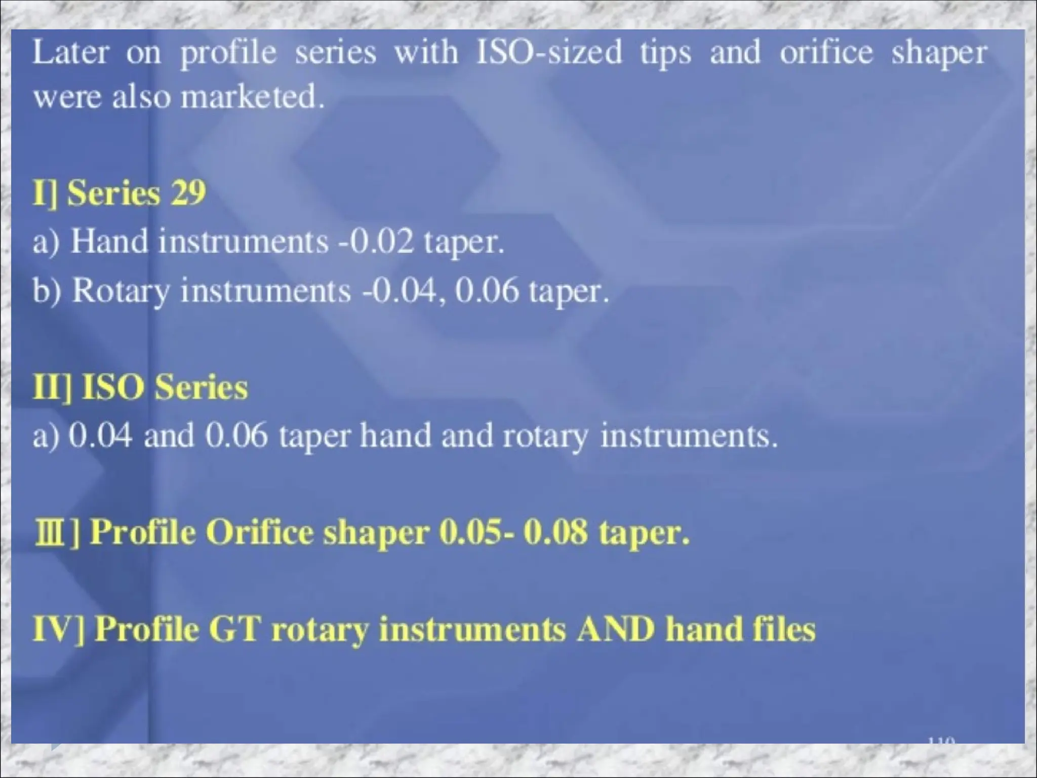
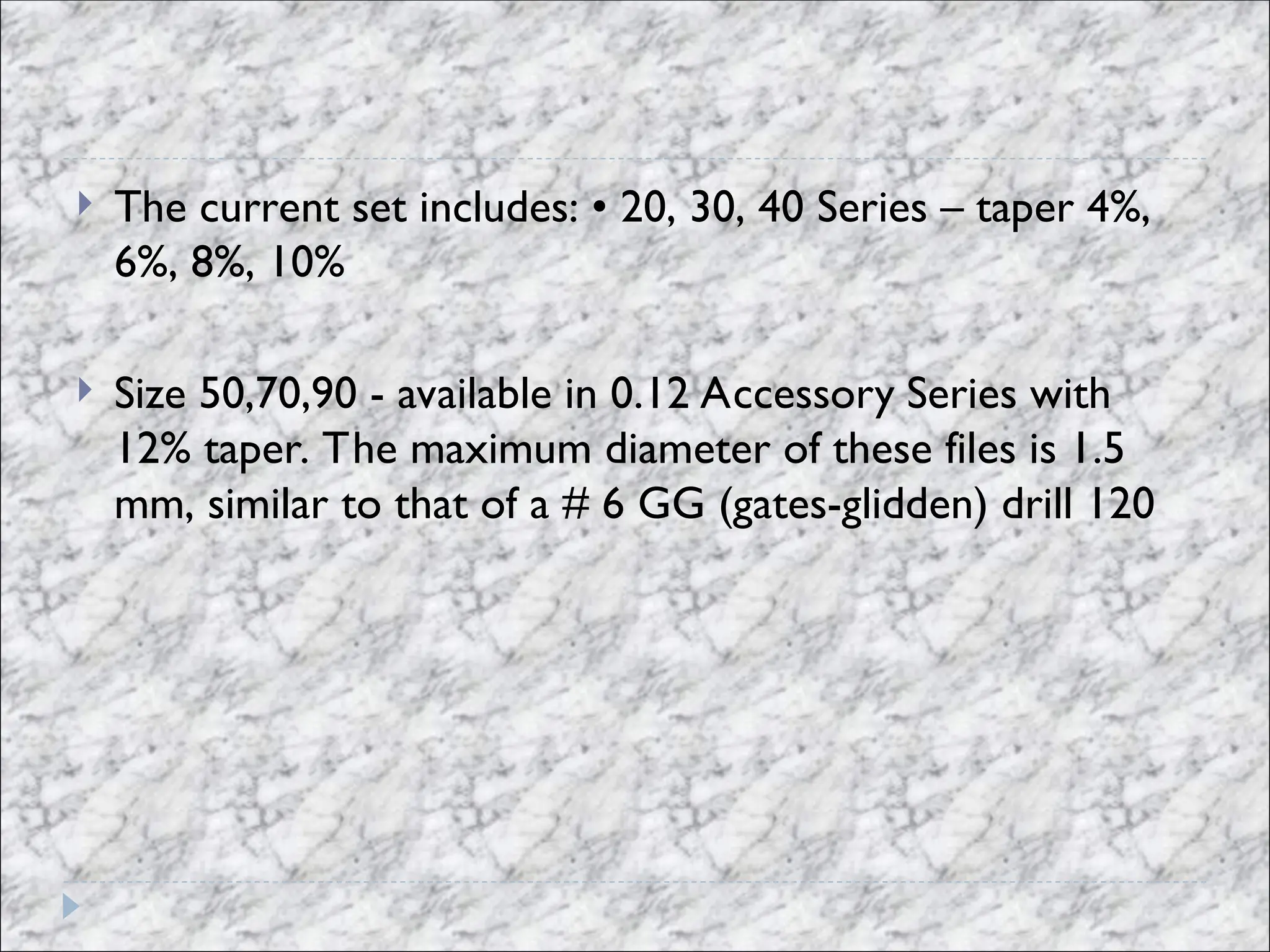
The currentset includes: • 20, 30, 40 Series – taper 4%,
6%, 8%, 10%
Size 50,70,90 - available in 0.12 Accessory Series with
12% taper. The maximum diameter of these files is 1.5
mm, similar to that of a # 6 GG (gates-glidden) drill 120
59.
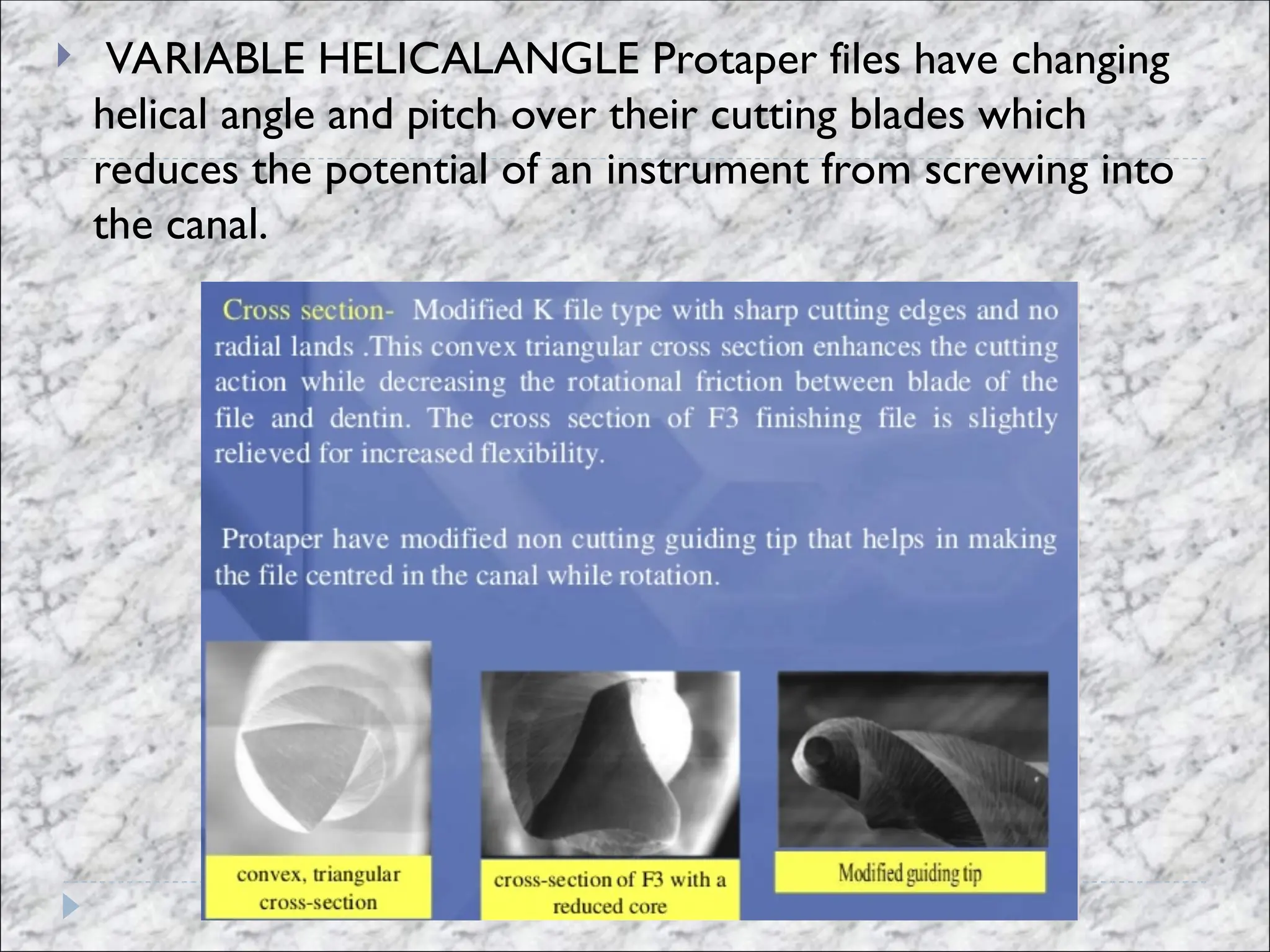
VARIABLE HELICALANGLEProtaper files have changing
helical angle and pitch over their cutting blades which
reduces the potential of an instrument from screwing into
the canal.
Editor's Notes
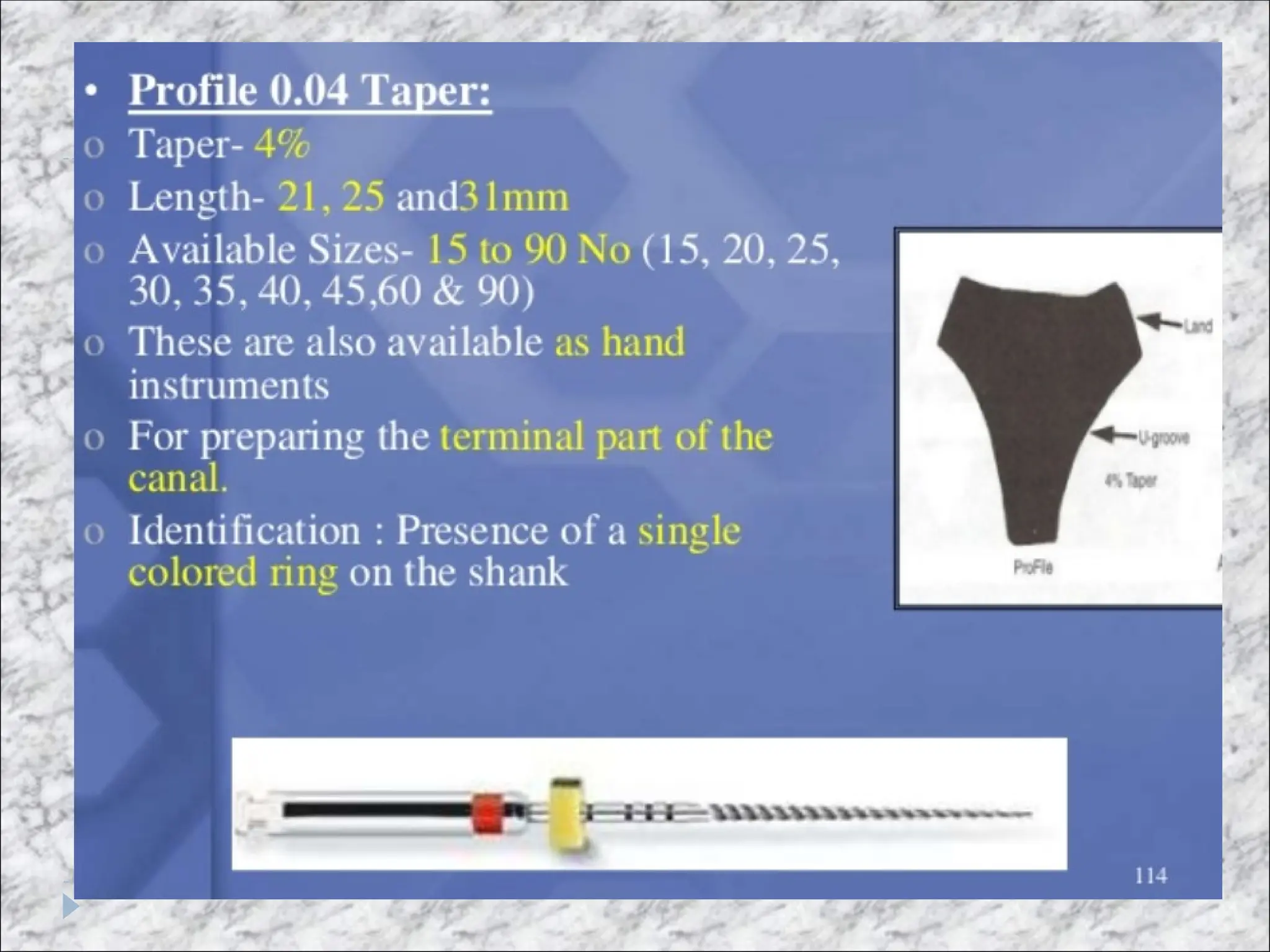
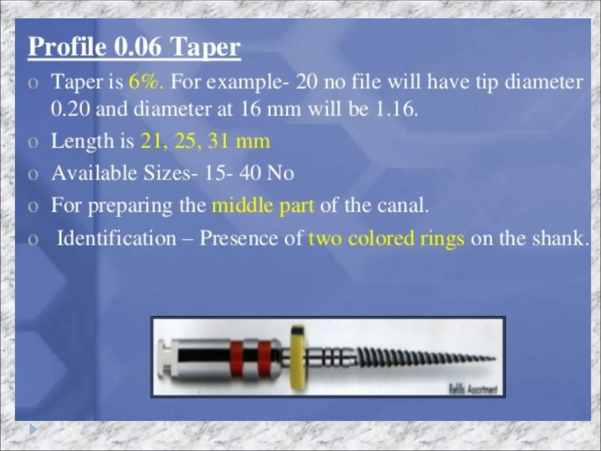
#7 Profile: Dr. Johnson
LightSpeed developed by Dr. Steve Senia and Dr. William Wildey, –
The Quantec developed by Dr. John McSpadden, –
And the Greater Taper files developed by Dr. Steve Buchanan
Father of niti files johnson and mcspaden
.
#26 An
overly positive rake angle will result in digging and
gouging of the dentin. This can lead to separation.