Download to read offline
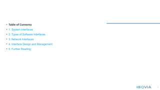
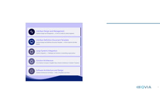


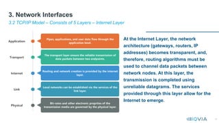
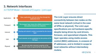
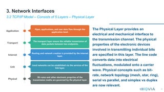
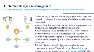

This document serves as a comprehensive guide on interface design and management for system engineers, emphasizing the crucial role interfaces play in connecting systems, applications, and components. It covers various types of interfaces, including user interfaces, file interfaces, and application programming interfaces (APIs), and discusses the importance of effective interface management in complex integration projects. Additionally, it provides insights into network interfaces, architectural principles, and usability heuristics essential for designing efficient and user-friendly interfaces.

![[2015/2016] Introduction to software architecture](https://cdn.slidesharecdn.com/ss_thumbnails/05softwarearchitecture-151203124359-lva1-app6891-thumbnail.jpg?width=640&height=640&fit=bounds)