What is DesignEngineering?
• Design engineering is a systematic approach to
converting software requirements into detailed
architectural and component-level specifications.
It involves defining how software will be
structured, how components interact, and how
data will flow through the system. It acts as the
blueprint for coding. Key concerns include
software structure, component interfaces, data
design, and implementation strategy. This phase is
critical in ensuring that the final product is robust,
maintainable, and meets user expectations.
3.
Design Engineering Concepts
•Core design engineering concepts include abstraction,
modularity, refinement, and refactoring.
• Abstraction simplifies complexity by focusing on
essential features.
• Modularity promotes reuse and parallel development.
• Refinement moves from high-level to detailed design.
• Refactoring improves internal code structure without
affecting behavior. Together, these principles help
build flexible, scalable, and maintainable systems.
4.
Software architecture
• Thedesign process for identifying the sub-systems making up
a system and the framework for sub-system control and
communication is architectural design
• The output of this design process is a description of the
software architecture
5.
Architectural design
• Representsthe link between specification and design
processes
• It involves identifying major system components and their
communications
6.
Architectural design process
•System structuring
• The system is decomposed into several principal sub-systems and
communications between these sub-systems are identified
• Control modelling
• A model of the control relationships between the different parts
of the system is established
• Modular decomposition
• The identified sub-systems are decomposed into modules
7.
Architectural models
• Differentarchitectural models may be produced during the
design process
• Each model presents different perspectives on the
architecture:
• Static structural model
• Dynamic process model
• Interface model
• Relationships model
8.
Architectural models
• Staticstructural model that shows the major system components
• Dynamic process model that shows the process structure of the
system
• Interface model that defines sub-system interfaces
• Relationships model such as a ERD
9.
System structuring
Concerned withdecomposing the system into interacting sub-
systems
• The architectural design is normally expressed as a block
diagram presenting an overview of the system structure
• (More specific models showing how sub-systems share data, are
distributed and interface with each other may also be developed)
10.
Packing robot controlsystem
Vision
system
Object
identification
system
A
rm
cont
roller
Gripper
controller
Packaging
selection
system
Packing
system
Conveyor
controller
The repository model
•Sub-systems must exchange data. This may be done in two ways:
• Shared data is held in a central database or repository and may be
accessed by all sub-systems
• Each sub-system maintains its own database and passes data explicitly
to other sub-systems
• When large amounts of data are to be shared, the repository model
of sharing is most commonly used (WHY???)
13.
Repository model
characteristics
• Advantages
•Sub-systems need not be concerned with how data is produced
• Centralised management e.g. backup, security, etc.
• Sharing model is published as the repository schema
• Disadvantages
• Sub-systems must agree on a repository data model. Inevitably a
compromise
• Data evolution is difficult and expensive
• No scope for specific management policies
• Difficult to distribute efficiently
14.
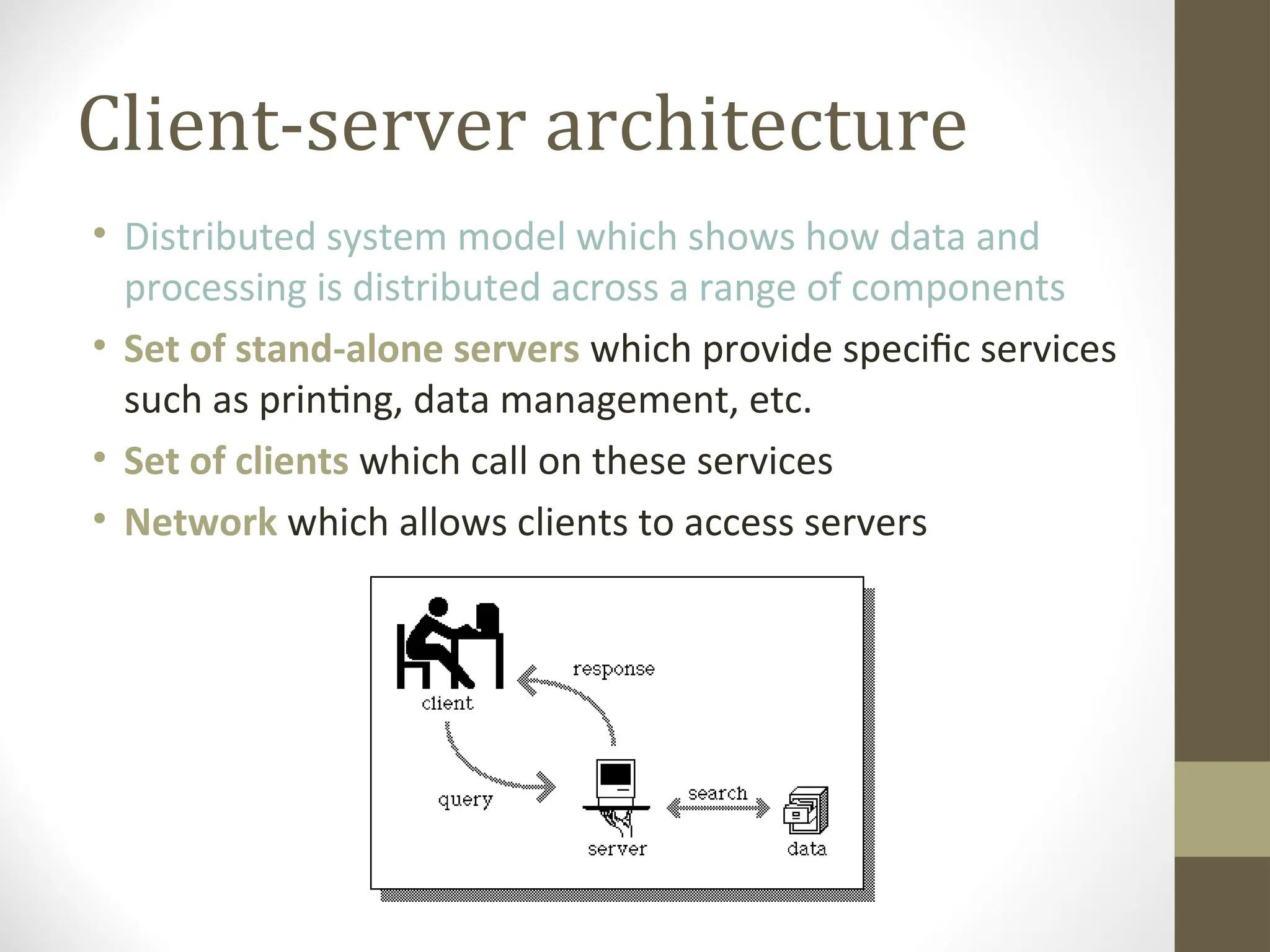
Client-server architecture
• Distributedsystem model which shows how data and
processing is distributed across a range of components
• Set of stand-alone servers which provide specific services
such as printing, data management, etc.
• Set of clients which call on these services
• Network which allows clients to access servers
15.
Client-server characteristics
• Advantages
•Distribution of data is straightforward
• Makes effective use of networked systems. May require cheaper
hardware
• Easy to add new servers or upgrade existing servers
• Disadvantages
• No shared data model so sub-systems use different data
organisation. data interchange may be inefficient
• Redundant management in each server
• No central register of names and services - it may be hard to find
out what servers and services are available
16.
Control models
Are concernedwith the control flow between sub systems.
• Centralised control
• One sub-system has overall responsibility for control and starts and stops
other sub-systems
• Event-based control
• Each sub-system can respond to externally generated events from other
sub-systems or the system’s environment
17.
Centralised control
• Acontrol sub-system takes responsibility for managing the
execution of other sub-systems
• Call-return model
• Top-down subroutine model where control starts at the top of a
subroutine hierarchy and moves downwards.
• Manager model
• Applicable to concurrent systems. One system component
controls the stopping, starting and coordination of other system
processes.
Event-driven systems
• Drivenby externally generated events where the timing of the
event is out with the control of the sub-systems which process the
event
• Two principal event-driven models
• Broadcast models.
An event is broadcast to all sub-systems. Any sub-system which can
handle the event may do so
• Interrupt-driven models.
Used in real-time systems where interrupts are detected by an interrupt
handler and passed to some other component for processing
21.
Broadcast model
• Effectivein integrating sub-systems on different
computers in a network
• Sub-systems register an interest in specific events. When
these occur, control is transferred to the sub-system
which can handle the event
• Control policy is not embedded in the event and
message handler. Sub-systems decide on events of
interest to them
• (!!!) However, sub-systems don’t know if or when an
event will be handled
Interrupt-driven systems
• Usedin real-time systems where fast response to an event is
essential
• There are known interrupt types with a handler defined for
each type
• Each type is associated with a memory location and a
hardware switch causes transfer to its handler
• (!!!) Allows fast response but complex to program and difficult
to validate
Distributed systems
archiectures
• Client-serverarchitectures
• Distributed services which are called on by clients. Servers that
provide services are treated differently from clients that use
services
• Distributed object architectures
• No distinction between clients and servers. Any object on the
system may provide and use services from other objects
• Multiprocessor architectures
• Simplest distributed system model
28.
Middleware
• Software thatmanages and supports the different
components of a distributed system. In essence, it sits in the
middle of the system
• Middleware is usually off-the-shelf rather than specially
written software
• Examples
• Transaction processing monitors
• Data converters
• Communication controllers
29.
Multiprocessor architectures
• Simplestdistributed system model
• System composed of multiple processes which may (but need
not) execute on different processors
• Architectural model of many large real-time systems
30.
A multiprocessor trafficcontrol system
Traffic lights
Light
control
process
Traffic light control
processor
Traffic flow
processor
Operator consoles
Traffic flow sensors
and cameras
Sensor
processor
Sensor
control
process
Display
process
31.
Client-server architectures
• Theapplication is modelled as a set of services that are
provided by servers and a set of clients that use these services
• Clients know of servers but servers need not know of clients
• Clients and servers are logical processes
• The mapping of processors to processes is not necessarily 1 : 1
Thin and fatclients
• Thin-client model
• In a thin-client model, all of the application processing and data
management is carried out on the server. The client is simply
responsible for running the presentation software.
• Fat-client model
• In this model, the server is only responsible for data
management. The software on the client implements the
application logic and the interactions with the system user.
35.
Thin and fatclients
Thin-client
model
Fat-client
model Client
Client
Server
Data management
Application
processing
Presentation
Server
Data
management
Presentation
Application processing
36.
Thin client model
•Used when legacy systems are migrated to client server
architectures.
• The legacy system acts as a server in its own right with a
graphical interface implemented on a client
• A major disadvantage is that it places a heavy processing load
on both the server and the network
• Online Gaming Service
37.
Fat client model
•More processing is delegated to the client as the application
processing is locally executed
• Most suitable for new C/S systems where the capabilities of
the client system are known in advance
• More complex than a thin client model especially for
management. New versions of the application have to be
installed on all clients
38.
Three-tier architectures
• Ina three-tier architecture, each of the application
architecture layers may execute on a separate processor
• Allows for better performance than a thin-client approach and
is simpler to manage than a fat-client approach
• A more scalable architecture - as demands increase, extra
servers can be added
39.
A 3-tier C/Sarchitecture
Client
Server
Data
management
Presentation
Server
Application
processing
40.
An internet bankingsystem
Database server
Customer
account
database
Web server
Client
Client
Client
Client
Account service
provision
SQL
SQL query
HTTP interaction