1. EE5381/7381
Lab 3 Fun With Real Audio
Introduction:
Analog to digital converters (ADCs) make it possible to digitize an analog voltage. By sampling an analog
voltage at a constant rate a digital representation of an analog signal can be created. In this lab we will
use an ADC to sample an analog signal from an audio source and send the digitized signal to a PC for
playback. This will take the next two lab sessions to complete.
Some Quick Sampling Theory:
To digitize an analog signal you must sample at least twice as fast as the highest frequency you’re trying
to capture (Nyquest) or there will be aliasing. For this lab a suitable sampling frequency would be 16k
samples per second. Sampling at 16k times per second with an 8 bit wide sample produces PCM quality
audio, which sounds pretty good.
Since you can’t guarantee that the input to the ADC will be in the range of frequencies that prevent
aliasing (0 Hz – 8,000 Hz) there must be an anti‐aliasing filter in series with the ADC. The anti‐aliasing
filter for our lab will be a simple low pass filter, frequencies from 0 Hz – 8,000 Hz will pass through filter
relatively unaffected and frequencies greater than 8,000 Hz will be attenuated.
Procedure:
1. Hook up the ADC and sample some voltages to make sure it’s working, and send samples out of
the Coldfire’s serial port using the “printf” command. Use HyperTerminal to monitor the
Coldfire’s serial port output.
2. Use a periodic interrupt timer to sample the ADC 16,000 times per second and test it out by
connecting a signal generator to the ADC’s input. Try sending samples from the ADC to MATLAB
over the Coldfire’s serial port and plot the results.
3. Build the anti‐aliasing filter circuit, sample some music, and play it back using MATLAB
Details:
Connecting the ADC
We’re using a Microchip MCP3001 ADC. The MCP3001 is a 10 bit, 200ksps ADC. This means that the
MCP3001 can convert an input voltage into a 10 bit number 200k times per second. The MCP3001 uses
SPI communications to transmit and receive data. What is SPI you ask? SPI stands for Serial Peripheral
Interface and is an easy to use method for communicating between electronic devices.
SPI is all about shifting bits. Here’s how SPI works in general: A master device, the Coldfire board, will be
connected to a slave device, the ADC. The master device controls all of the communications transactions
and slave does as it’s told. Four signals connect the master and slave: a chip select, data input, data
output, and a clock. As data is clocked out of the master’s SPI shift register to the slave device’s SPI shift
register, the slave device clocks data from its SPI shift register back to master’s SPI shift register.
2. EE5381/7381
Lab 3 Fun With Real Audio
The MCP3001 is a simple SPI device in that it only outputs data (this means it has no inputs). In order to
initiate a SPI transfer on the Coldfire data must be sent though. The solution is simple; the Coldfire just
sends some junk data out of its unconnected data output to initiate a SPI transfer
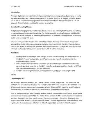
Figure 1, MCP3001 timing diagram
The ADC will be connected to the Coldfire with 3 pins, the clock (QSPICLK), data input (QSPIDIN), and
chip select pins (QSPICS0). When a transfer is initiated on the Coldfire the Chip select will be brought
low. Then the Coldfire will output 13 clock transitions. During the last 10 clock transitions the ADC will
output its 10 bits of data back to the Coldfire.
The SPI hardware on the Coldfire is called the QSPI module, the ‘Q’ stands for queued, and here’s how it
needs to be setup to work with the ADC:
1. The QSPI_PAR register needs to be configured so that the QSPI pins aren’t GPIO
2. The QMR register needs the following set: Master mode, the length of the transfer (13 bits), and
baud rate (0x0032 will work), and the CPHA bit needs clearing
3. In the QWR register the CSIV bit needs setting
4. Set the QAR register to point to Command RAM
5. Write a 0x7E00 to the QDR register
6. Set the SPE bit in the ODLYR register to initiate a transfer
7. Wait until the SPIF bit in the QIR register is set
8. Set the QAR register to point to the Receive RAM
9. Read the QDR register to retrieve the reading from the ADC
10. Repeat steps 5 to 9 to get more readings
Periodic Interrupt Timers
The mcf5235 has 4 periodic interrupt timers (PITs). These timers allow the user to create interrupts at
specific rates. These interrupts cause the processor to halt what it’s doing and execute a specific chunk
of code at a constant rate. Setting up the PITs isn’t hard, but due to time constraints code will be
provided to setup and use the PITs.
Anti‐aliasing filter and scaling circuit ???????
Appendix A