
Recommended
More Related Content
What's hot
What's hot (20)
Similar to Measure and maintain water pressure with gauges and valves
Similar to Measure and maintain water pressure with gauges and valves (20)
More from siddharthasenguptaSi
More from siddharthasenguptaSi (15)
Recently uploaded
Recently uploaded (20)
Measure and maintain water pressure with gauges and valves
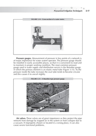
- 1. Pressure gauges. Measurement of pressure in key points of a network is of major importance for water system operator. The pressure gauge should be installed in easily accessible places, so that it is convenient to read and to maintain in proper working condition. The most common pressure gauge used in water supply and distribution service is the Bourdon gauge, in which the primary element is an elastic metal tube (Figure 3.15). As the pressure inside the tube increases the oval tube tends to become circular and this causes it to uncoil slightly. Air valves. These valves are of great importance as they protect the pipe network from damage by trapped air in the system or from collapse due to a vacuum. If improperly chosen or located in a wrong place, it can also cause severe functional problems. Pressurized Irrigation Techniques Pressurized Irrigation Techniques 3.17 FIGURE 3.14 - Cross-section of a water meter. FIGURE 3.15 - A Bourdon type pressure gauge.
- 2. The presence of free air in water installations causes many difficulties in the piping system at start-up, during operation and when draining the system. Air valves are needed so that air can be either released from or admitted into the pipelines. Its operation and air flow rate cannot be influenced either by the system operator or by the performance of any other appliance (Figure 3.16). There are three main kinds of air valves: Single automatic air release valves, for the continuous automatic release under pressure of the trapped air pockets accumulated at the summits of the mains. The single air valves are small in size with a 1 inch threaded connection, larger sizes not being required. They are installed on risers above ground at the high points of the conveyance and mains or every 200 m. Large orifice air-vacuum valves (low pressure kinetic), for releasing or admitting air in bulk when filling or draining the system. They do not function under pressure. During normal operating conditions, a float held up by the system water pressure closes the large orifice. Sizes of 2 inches can meet the system requirements of 160 mm pipelines. They are installed at high points of the system after the pump or the system’s main service hydrant on the head control unit, and at the beginning and the end of long branch pipelines. Double (dual) air valves, which are a combination of the two above. They are the safest and most efficient air valves in mains and conveyance lines during filling, draining and operating the piped irrigation systems. The 2 inches size of the double air valve is appropriate for most on-farm piped irrigation installations up to 160 mm in diameter. In addition to the above air valves, small vacuum breakers of inch are available for preventing vacuums in drip laterals laid on the soil surface, thus protecting them from clogging. Air valves are manufactured for high working pressures of at least 10.0 bars PN. They are installed on-line with threaded internal or external joints. Pressurized Irrigation Techniques Chapter 3 – Irrigation equipment and jointing techniques 3.18 1 2 3
- 3. Safety valves (also called pressure relief valves). The practical use of safety valves began with steam boilers so that steam was released at critical pressures to avoid bursting of tanks and pipes. In water supply systems, the compressibility of water is very low and the problem of safety is therefore smaller. However, it is used mainly to ensure proper working of a system in cases of failure of other pressure control appliances. Safety valves are on-line valves of smaller diameter than the pipelines, spring-loaded or otherwise, in which the outlet is inclined 90º to the inlet. When the pressure in the system exceeds the pre-set value, the valves open and release water into the air. Thus, they prevent the pipes from bursting due to sudden high pressures which might occur in the system. They are located immediately upstream of the main valve of the system. They are available in sizes of 1–3 inches with threads (Figure 3.17). Pressurized Irrigation Techniques Pressurized Irrigation Techniques 3.19 FIGURE 3.16 - Air valves operate by introducing and releasing air to the water system. FIGURE 3.17 - Scheme and photograph of a safe valve.
- 4. Pressurized Irrigation Techniques Chapter 3 – Irrigation equipment and jointing techniques 3.20 FILTERS The filtration of the irrigation water is essential in order to avoid blockage damage to the micro-irrigation emitters. The type of filter used depends on the kind of impurities contained in the water and the degree of filtration required on the emitters. Their size should be the most economical with the lowest friction losses ranging from 0.3–0.5 bars. The following kinds of filters are available: Gravel filters. These filters, also called media filters, are closed cylindrical tanks which contain a gravel grain of 1.5–3.5 mm or a basalt sand filter bed. Where the irrigation water source is an open reservoir, they are installed at the beginning of the head control of the system. Water entering the tank from top passes through the gravel bed, which traps the large particles of unbroken organic matter, mostly algae, and exits through the outlet at the bottom of the tank. They are equipped with the necessary inlet, outlet and drain valves, and a back-flushing arrangement. The filter body is epoxy coated metal, minimum 8.0 bars PN, and is 50–180 cm high and 40–100 cm in diameter. They are available in threaded connection sizes of 1 to 8 inches (Figure 3.18). Hydrocyclone (sand separator) filters. These are closed conical metal tanks placed at the beginning of the head control unit where needed. They separate sand or silt from well or river water through the creation of a centrifugal force by a vortex flow inside the filter. This force drives the solids downward to a collecting chamber attached below and lets the clean water out. They are epoxy coated, PN 8.0 bars, and are available in threaded connection sizes of to 8 inches (Figure 3.19). FIGURE 3.18 - Scheme and photograph of a gravel filter.
- 5. Screen type filters. These are used for final filtration as a safeguard for either moderate quality water or following a primary filtration with gravel or hydrocyclone filters. They are installed at the end of the head control before the main pipeline. They are made of epoxy coated metal or high engineering plastics in various cylindrical shapes (horizontal on-line, vertical angle, etc.), and are equipped with interchangeable perforated filtering elements, inlet, outlet and drain valves and pressure inspection gauges. They can withstand a working pressure (PN) of 8.0 bars. The degree of filtration ranges from 60 to 200 mesh (75 microns). They are available in sizes of to 4 inches. Smaller sizes are made of reinforced plastic (Figure 3.20). Pressurized Irrigation Techniques Pressurized Irrigation Techniques 3.21 FIGURE 3.19 - Scheme and photograph of hydrocyclones. FIGURE 3.20 - Operational scheme and photograph of a screen filter.
- 6. Pressurized Irrigation Techniques Chapter 3 – Irrigation equipment and jointing techniques 3.22 Disk type filters. They are cylindrical, made of reinforced plastic, horizontal in-line or vertical angle-shaped. The filtering elements consist of stacks of grooved plastic rings with multiple intersections providing a three dimensional filtration of high level. They are very effective in removing all kinds of impurities of inorganic and organic origin, algae included. The degree of filtration can range from 40 to 600 mesh (400–25 microns). They are available in all sizes ( to 6 inches), PN 8.0 bars, with threaded joints. They are placed at the end of the control unit before the main pipeline (Figure 3.21). Automatic self-cleaning filters. Most of the different kinds and types of filters can be supplied with an automatic cleaning capability, as determined by pressure differential, duration of filtration, volume of water filtered, or by any combination of these. The cleaning mechanism, usually back flushing, for the removal of accumulated debris uses the system’s water pressure. It is activated: a) whenever the pressure difference across the filter body increases to a predetermined value, e.g. 0.5 bar; and b) at fixed time intervals with an electronic timer back-up (Figure 3.22). FIGURE 3.21 - A grooved disk and a disk filter. FIGURE 3.22 - An automatic self-cleaning filter uses the back flushing mechanism for the removal of accumulated debris.
- 7. FERTIGATION EQUIPMENT Fertilizers are applied with the irrigation water through the system using special devices called fertilizer injectors installed at the head control. There are three main types of fertilizer injectors: closed tank, Venturi type and piston pump. All of them are water driven by the operating pressure of the system. Fertilizer (closed) tank. This is a cylindrical, epoxy coated, pressurized tank, resistant to the system’s pressure, and connected as a bypass to the supply pipe of the head control. It is operated by differential pressure created by a partially closed valve, placed on the pipeline between the inlet and the outlet of the tank. Part of the flow is diverted to the tank entering at the bottom. It mixes with the fertilizer solution and the dilution is ejected into the system. The dilution ratio and the rate of injection are not constant. The concentration of fertilizer is high at the beginning and very low at the end of the operation. However, this apparatus is still in service on a very small scale in some countries because of its low cost and easy manufacture (Figure 3.23). Venturi type. This is based on the principle of the Venturi tube. A pressure difference is needed between the inlet and the outlet of the injector. Therefore, it is installed on a bypass arrangement placed on an open container with the fertilizer solution. The rate of injection is very sensitive to pressure variations, and small pressure regulators are sometimes needed for a constant ejection. Friction losses are approximately 1.0 bar. The injectors are made of plastic in sizes from to 2 inches and with injection rates of 40–2 000 litres/h. They are relatively cheap compared to other injectors (Figure 3.24). Pressurized Irrigation Techniques Pressurized Irrigation Techniques 3.23 FIGURE 3.23 - Scheme and photograph of a fertilizer closed tank.
- 8. Pressurized Irrigation Techniques Chapter 3 – Irrigation equipment and jointing techniques 3.24 Piston pump. This type of injector is powered by the water pressure of the system and can be installed directly on the supply line and not on a bypass line. The system’s flow activates the pistons and the injector is operated, ejecting the fertilizer solution from a container, while maintaining a constant rate of injection. The rate varies from 9 to 2 500 litres/h depending on the pressure of the system, and it can be adjusted by small regulators. Made of durable plastic material, these injectors are available in various models and sizes. They are more expensive than the Venturi type injectors (Figure 3.25). WATER EMITTERS The water emitters specify the kind of system and in most cases the type of installation. Fitted on the laterals at frequent spaces, they deliver water to the plants in the form of a rain jet, spray, mist, small stream, fountain or FIGURE 3.24 - Scheme and photograph of a Ventury type fertilizer. FIGURE 3.25 - Scheme and photograph of a piston pump fertilizer.
- 9. continuous drops. All kinds and types of emitters in use now are of the small orifice-nozzle, vortex or long-path labyrinth types. Thus, the flow in the water emitters is turbulent. Some drip emitters of laminar flow used in the past are no longer available. Sprinklers. Most of the agricultural sprinklers are the hammer-drive, slow rotating impact type, single or twin nozzle. The sprinklers shoot jets of water into the air and spread it to the field in the form of raindrops in a circular pattern. They are available in various nozzle sizes, flow discharges, operating pressures and wetted diameters or diameter coverage, full circle or part circle. They are classified as low, medium and high pressure/capacity, as shown in Table 3.5; according to the height of the water jet above the nozzle, they are divided into low angle (4º–11º), or high angle (20º–30º). They are made of brass or high engineering plastics with internal or external threaded connections of –1 inch. They are installed vertically on small diameter riser pipes, 60 cm above ground, fitted on the laterals. The sprinkler spacing in the field is rectangular or triangular at distances not exceeding 60 percent of their diameter coverage. Filtration requirements, where necessary, are about 20 mesh (Figure 3.26). Pressurized Irrigation Techniques Pressurized Irrigation Techniques 3.25 TABLE 3.5 - Sprinkler classification Agriculture sprinklers Nozzle size mm Operating pressure Flow rate Diameter (two nozzle) (bars) (m3 /h) coverage (m) Low pressure 3.0–4.5 x 2.5–3.5 1.5–2.5 0.3–1.5 12–21 Medium pressure 4.0–6.0 x 2.5–4.2 2.5–3.5 1.5–3.0 24–35 High pressure 12.0–25.0 x 5.0–8.0 4.0–9.0 5.0–45.0 60–80 FIGURE 3.26 - Rotating sprinklers.