1. F
0.600 3.061 0.600
4.262
7.431
1.579
0.979
5.038
3.098
3.070
0.400
0.813
HALL
LOUNGE
PLAYROOM
KITCHEN
djacent
operty
Existing
M/H
RWP
RWP
RWP
Existing
SVP
TD
Existing
B.I.G
WM
6.6250.600
3.224
0.600
0.2500.900
0.600
Thermal Block
Cavity Fill
Hardcore
DPM 1200g
DPCGL DPM 500g
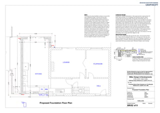
Proposed Side & Rear Extension at 4 Ty-Newydd,
Whitchurch, Cardiff. CF14 1NN
Drawn by Date
M Ferreira 02/2011
Checked by Date
B McCarthy 02/2011
1:50 on A3
Drawing Name
Drawing Scale
Drawing Number: Status Revision
BR/02 of 9
Job Title
Proposed Foundation Plan
Proposed Foundation Floor Plan
RadonRadonRadonRadon
The proposal has been identified as being in an area which
may be affected by Radon. Once the work has been
completed it is advisable that the property is tested in
accordance with National Radiological Protection Board's
recommendations. Any cracks or service entries in the
existing floor of the building should be sealed to an airtight
standard. Provide a Radon membrane to the floor of the
proposed extension/building (a membrane of at least 1200
gauge polythene is required). Provide Radon proof trays in
the cavity walls of the extension/building linked to the floor
membrane. Joints between a floor membrane and any
cavity wall trays should not form a slip plane and the joints
are to be hermetically sealed or taped so as to be airtight.
A Radon proof barrier is to be continued across the party
wall to act as a drainage channel. Service penetrations are
to have an airtight seal. Due to the presence of Radon in
this area stepped foundations should be avoided.
Underground DrainageUnderground DrainageUnderground DrainageUnderground Drainage
All pipework in flexible jointed plastic or other approved laid on approved bed. All
drains under and within 1m of a building to be encased in minimum 150mm
concrete with joints remaining flexible. Rocker pipes with flexible joints to be
provided through walls. All drain trenches within 1m of any foundation to be bedded
and surrounded and trench backfilled with concrete. Where the crown of the pipe is
within 300mm of the underside of the slab, concrete encasement should be used
integral with the slab. Drains with less than 1200 cover under Highways/Pavement
to be encased in 22.5/20 kn m2 concrete minimum 150 thick. All concrete
encasements to have expansion joints at intervals not exceeding 9m maximum.
Manholes/Inspection chambers in 225 Class 'B' engineering bricks laid in water
bond in cement mortar on minimum 150 concrete base: or other approved system.
Covers and frames to B.S. 497 set in concrete top and surround. All to the
approval of the Local Authority. Soakaways, where used, to be minimum 4.5m from
any building, and to comply with B.R.E. Digest No. 365.
Above Ground DrainageAbove Ground DrainageAbove Ground DrainageAbove Ground Drainage
All to B.S. 5572 (1978) Waste Pipe sizes W.H.B. 32mm: sink and shower 40mm,
W.C. 110mm, W.H.B. increased to 40mm over 1.7m long (up to 3.0m max) and
50mm for showers over 3.0m long (up to 4.0m max). All seperate connections. 75
deep seal traps to 110 UPVC soil and vent pipe terminating with suitable durable
cage minimum 900 above window heads. Rainwater Fittings to match existing.
BMac Design & Developments
07766 317970 / 02920 310595
3 Bishops Road, Whitchurch, Cardiff. CF14 1LT
Scaled dimensions may be used for approximation.
Ensure only figured dimensions are used for
construction. All dimensions to be checked on site.
BIG - Back Inlet Gully
SVP - Soil & Vent Pipe.
External water tap.
RWP - Rainwater pipe to be connected to
the existing surface water drainage or
soakaway.
M/H - Manhole
Typical Foundation DetailTypical Foundation DetailTypical Foundation DetailTypical Foundation Detail
Foundation design to be checked with Building
Control and in accordance with Structural
Engineers design and geotechnical report.