Nexans Euromold Interface C 400 Compact Series Cable Connectors
electrical sub dwg1.4.5-Layout1
1. 450
500
7.3 One 16 A switched socket outlet shall be positioned as shown in Section B-B of the
The fitting shall have a minimum Ingress Protection rating of IP 55.
7.4 1200 mm fluorescent, double tube fitting (40 W rating) shall be positioned as shown.
7.2 DB shall be six-way. The main incoming supply shall be protected using a 32 A double Pole
7.1 A 25 mm PVC conduit with draw wire installed shall be provided from distribution board
5.2 Roof and floor slab shall be as specified by a Structural Engineer
5.4 Floor shall be screeded level with 50 mm thick 1:3 mix.
5.7 Floor slab in transformer bay shall carry a mass of 6 000 kg.
6.3 Two lifting slots 50 mm x 100 mm shall be provided in each section.
6.4 Each section shall not exceed a length of 600 mm.
Permanent vehicle access to substation, 10 000mm wide x 3000mm high
6.1 All trenching shall be covered with approved resocrete infill panels.
6.2 Recess around trench edges shall be 25 mm deep and 40 mm wide.
6.5 Pvc cable ducts in accordance with SANS 61 386-1 and SANS 61 386-24 shall be used
7.0 INSTALLATION WIRING
5.0 ROOF, WALLS AND SLAB
The recess shall be achieved using galvanized angle iron(refer to Trench recess and
under all hardened surfaces to boundary.
6.0 TRENCHING
5.1
shall be provided.
1.0 ACCESS TO SUBSTATION
7.5 The LV supply for DB shall, as far as possible, be provided by eThekwini Electricity.
7.6 The DB, all PVC piping, socket outlet and light switch shall be recessed within the
Two-way switching between transformer bay and M.V. switch room shall be provided.
6.6 Cable entry to be front entry to terminate onto road frontage as indicated.
5.6 Floor slab in MV switch room shall carry a mass of 1 000 kg per m of floor.
5.5 Floor to be level within +/- 1mm/m sq.
5.8 Where embankment's slope towards the building, the walls shall be waterproofed.
These ducts shall be capped to prevent any flow of ground water into trenches.
Din type fuse holder with neutral link, fused at 32Amp, 1x 16Amp fuse holder, fused at
drawing. The normal switched socket outlet shall be labeled "Use with portable
bricks an plaster.
11.0 CONSUMER BUS TRUNKING UNIT
11.1 One unit shall be built in as shown with the flange sides on the Consumer Meter room side.
11.2 Busbar trunking unit maybe positioned between a distance of 200 mm and 1200 mm from
11.3 Busbar trunking shall be positioned at a minimum height of
11.4 The current rating shall be as indicated in note 2 of the consumer bus trunking drawing.
drain detail' on drawing).
16Amp for the plug circuit, and 1 x 10Amp fused holder,fused at 10 Amp for light circuit.
1000mm above finished floor level.
The substation building shall be built using motar and clay bricks.
5.3 Internal roof slab and walls shall be plastered and painted white.
9.2 All vents on duct shall be covered with 10mm hot-dip galvanized wire mesh or
9.0 VENTILATION
Galvanised cable tray in transformer bay to be installed by contractor after transformer
similar (not gauze),on inside.
9.1 The transformer bays shall be vented as indicated.
has been positioned. The cable rack shall be a 600 mm wide heavy duty tray. The position,
Length and route shall be agreed upon between the Consumer's contractor and the local
eThekwini Depot Superintended or Clerk of Works.
10.0 CABLE TRAY
(DB) to the cable trench.
2.0 MEDIUM VOLTAGE SWITCH ROOM
Size: 3 800 mm (Length) x 2 050 mm (width) x 3 100 mm (Height).
8.3 All doors shall open outwards. Open door retainers shall be fitted to hold the doors
locking bolt of the barrel bolt and three pointlocking mechanism of the doors when in
8.4 Galvanised steel pipes shall be embedded into the concrete floor to accept the floor
8.2 D3 - Centre opening bottom-vented double door in two equal halves , shall have a clear
8.0 DOORS
8.5 All doors shall be adequately bonded and earthed via a flexible braided earth conductor.
8.6 Padlocks (SS) shall be fitted to medium voltage switch room door D4, transfomer bay
the closed position.
opening of 2 000 mm wide x 2 400 mm high and shall be manufactured as per drawing.
door D3 (obtainable from eThekwini Electricity's Customer Services Division).
in the open position.
The minimum cross sectional area of the earth conductor shall be less than 2,5 mm. This
earth conductor shall be be connected to the main substation earth bar which is housed
within the cable trench . The earth conductor shall be drawn trough a 20 mm PVC conduit.
This conduit shall be recessed within the concrete floor.
SPECIFICATIONS:
3.0 TRANSFORMER BAY
Size: 3900 mm (Length)x 2 300 mm (width) x 3 100 mm (Height).
9.3 In transformer bay if cross ventilation is not possible through D3 door and rear
ventilation,a mechanical fan (conection driven) shall be mounted on the wall of the
9.4 The mechanical fan and any associated equipment shall either be manufactured of 3CR12
steel,or stainless steel (marine grade 316) or hot-dip galvanized mild steel for heavy
2
substation.
duty application.
adjacent wall.
earth leakage."
4.0 METER PANEL
8.1 D4 Single door , shall have a clear opening of 900 mm wide x 2 400 mm high,and shall
be manufactured as per drawing MRD.
6.7 All trenches shall slope towards a drain outlet pipe.The slope shall be at least 1/30
gradient. The drain outlet pipe shall be connected to the storm water system in
accordance with the National Building Regulations and Municipal By-laws. The direction
of drainage shall be in accordance with the Storm Water Engineers detail.
refer to note 6.8
light fitting
2way light
switch
2way light
switch
DB (refer to note 7.6)
light fitting
CB
CB
300
300600wide,
900deep
300
300
300
300
vented
refer to note 7
TRENCH DRAINAGE POINT
(SEE NOTE 6.7)
600 wide,
900 deep
D
D4
D3
scale : 1:50
PLAN VIEW
refer to note 6.8
220 900 220 1260 7852000
2734 3347
220 2734 3347 220
6081
220220
D
3615
100
220
696 220
6522
6081
600
4400
115
1000
17772324
CUTFIELD PLACE
WESTRIDINGROW
SITE PLAN - 1:1000
W
EST
R
ID
IN
G
R
O
W
PROPOSEDSUBSTATION
1xbulkwatermeter&fire
hosereels
twinboosterconnection
postboxes
stormwatergrid
gm
33343537363840394142
4123
32
16
23
22
21
20
19
18
17
15
1413
31
30
292827
26
25
24
12111097865
PROPOSED SUBSTATION
scale : 1:30
DOOR - D4
scale : 1:30
DOOR - D3
40
25
NGL
3410
scale : 1:50
SECTIONAL ELEVATION A-A
GRD FLR
900
200
100.000
SUBSTATION
LEVEL
103.410
ROOF
LEVEL
900
859
shown dotted behind
stormwater pipe connected
to stormwater drainage
(direction of drainage to engineer`s
details (refer to note 6.7)
vented - (See note 9)
BUS COUPLING
TO ENGINEER
SPECIFICATION
TO BASEMENT
PANEL
24402018
600
900
refer to note 6.8
115
115
900
scale : 1:50
SECTIONAL ELEVATION B-B
NGL
16 A switched
(refer to note 7.3)
3100
1911 1354
500
1500
socket outlet see
NGL
LIGHT FITTING
shown dotted beyond
(refer to note 6.8)
904 115115
(refer to note 7.6)
DB
TYPICAL DETAILS FOR DOORS
Scale - 1:30
Section X-X
Scale - 1:40
100.000
SUBSTATION
LEVEL
103.410
ROOF
LEVEL
scale : 1:50
SECTION CC
3410
LIGHT FITTING
200
NGL
1800
GROUND FLOOR
METER ROOM
1500
BUS COUPLING
RISING MAIN BUS COUPLER
refer to note 6.8
152
500
MAIN CIRCUIT BREAKER
CIRCUIT BREAKER
TERMINATION
SECTORIAL
CONDUCTORS
TUFFNOL SUPPORT INSULATOR
MAIN LV PANEL
2mm MILD STEEL
ENCLOSURE
WATER PROOF
SEAL
VOID PENETRATION
TERMINATION
HATCH
HEAT SHRINK
INSULATED
MUNICIPAL SIDE
TERMINATION ENDS
FIRST FLOOR
CONCRETE SLAB
TERMINATION
CONSUMER SIDE
98.200
SUBSTATION
LEVEL
1800
scale : 1:50
X
D3
X
ONE COURSE
BRICKWORK
BELOW
INTERNAL
FLOOR
FRONT ELEVATION
CABINET HOOKS ON SIDES OF DOORS
SUBSTATION
LEVEL
ROOF
LEVEL
X
BACK ELEVATION
scale : 1:50
METER ROOM DOOR
2000
1700
SECTION D-D
BUS COUPLING
RISING MAIN BUS COUPLER
150
250
1800
scale : 1:50
refer to note 6.8
1500
DB
1500
(refer to note 7.6)
1802
320 Smith Street
1102 Mercury House
Durban
4000
Telephone: 031 3012253
Email: ugesiafricaconsulting.co.za
Website: www.ugesiafrica.co.za
Consultant Signature:___
Client Signature:__
Client:
Project By:
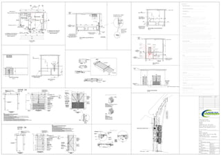
Title:
Sub-Station Layout
Level:
Ground
Revision:
Rev 01
Scale:
As Shown
Dwg. No:
Drawn By:
ATANG MAPHELA
Checked By:
Zaid Ally
Date:
15-07-2016
Sheet No.:
01 of 01
Rev. No: Description Of Project Date
BLUE HORIZON
PTN 179(OF 136) OF THE FARM
RIDING NO:15152
3A CUTFIELD PLACE , SHERWOOD
BH-S/S-2016-05