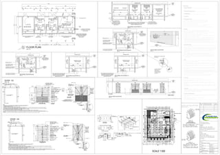
1. MEDIUM VOLTAGE
SWITCH ROOM
D3 D4
LIGHT FITTING
TRENCH DRAINAGE POINT
(SEE NOTE 6.7)
600 wide, 900 deep
CABLE ENTRY FROM SIDE
pvc ducts under all hardened
surfaces to boundary
(see note 6.6)
(see note 6.8)
DB (see note 7.6)
PVC DUCTS
3000
300
300
400
LIGHT FITTING
8003000
600
600
6001285
800
900 deep
3570600
300
600 wide,
1300
900deep
600wide,
A
LIGHT FITTING
BC
C B
D
D
600
900deep
600wide,
300
METER ROOM
LIGHT
FITTING
LIGHT FITTING
VENTED
(SEE NOTE 8)
D3
600
6001285
900 deep
300
600 wide,
FITTING LIGHT
900deep
600wide,
620
900deep
600wide,
LIGHT
FITTING
TRANSFORMER
BAY 02
E
E
500
528030003000
14435
4400
14301430
2000
D1
230
A
2way
light switch
scale : 1:50
FLOOR PLAN
FITTING LIGHT
TRANSFORMER
BAY 01
115
230230
8709002630
230
4002000600
115
2000600
230
17601000
240
230
900 deep
400 wide,
900deep
600wide,
400
700
300
700
300
2way
light switch
800
2way
light switch
CONS. BUS TRUNKING UNIT
(SEE NOTE 11)
4860
CONN.INTOS/WLINE
115
900
2340
LIGHT FITTINGLIGHT FITTING
2200
shown dotted behind,
shown dotted behind stormwater pipe connected
to stormwater drainage (direction of drainage to
engineer`s details (see note 6.7)
shown dotted behind
concealed consumer
bus trunking unit
(see note 11)
TRANSFORMER
ROOM 02
MEDIUM VOLTAGE SWITCH ROOM
3000600400 6006003685
115115
scale : 1:50
SECTIONAL ELEVATION A-A
30004400
NGL
vented
660
1430
METER ROOM
1285
3000
TRANSFORMER
ROOM 01
600400 600
115
3000
vented
1430
1285
100.000
SUBSTATION
LEVEL
103.000
ROOF
LEVEL
PARKING DECK
shown dotted behind
under hardened surfaces
(see note 6.8)
scale : 1:50
SECTIONAL ELEVATION B-B
charger
battery
1500
coms.
panel pilot
board
8006003000
1000
470
690
600
700
900
MEDIUM VOLTAGE
SWITCH ROOM
4400
DB (see note 7.6)
100.000
SUBSTATION
LEVEL
103.000
ROOF
LEVEL
PARKING DECK
3000
100
dedicated 16 A switched
socket outlet (see note 7.3)
16 A switched socket
outlet (see note 7.3)
to be installed by
ethekweni electricity
(see note 7.5)
900
scale : 1:50
SECTIONAL ELEVATION C-C
3000600
shown dotted behind stormwater pipe
connected to stormwater drainage
(direction of drainage to engineer`s
details (see note 6.7)
800
MEDIUM VOLTAGE
SWITCH ROOM
4400
PARKING DECK
100.000
SUBSTATION
LEVEL
103.000
ROOF
LEVEL
600
900
scale : 1:50
SECTIONAL ELEVATION C-C
3000600
shown dotted behind stormwater pipe
connected to stormwater drainage
(direction of drainage to engineer`s
details (see note 6.7)
800
MEDIUM VOLTAGE
SWITCH ROOM
4400
PARKING DECK
100.000
SUBSTATION
LEVEL
103.000
ROOF
LEVEL
600
40
40
scale : 1:50
SECTIONAL ELEVATION B-B
charger
battery
1500
coms.
panel pilot
board
8006003000
1000
470
690
600
700
900
MEDIUM VOLTAGE
SWITCH ROOM
4400
DB (see note 7.6)
100.000
SUBSTATION
LEVEL
103.000
ROOF
LEVEL
PARKING DECK
3000
100
dedicated 16 A switched
socket outlet (see note 7.3)
16 A switched socket
outlet (see note 7.3)
to be installed by
ethekweni electricity
(see note 7.5)
CABINET HOOKS ON
SIDES OF DOORS
D1
X
D3
X X
D3
XX
PARKING DECK
D1
X
100.000
SUBSTATION
LEVEL
103.000
ROOF
LEVEL
scale : 1:50
SOUTH EAST ELEVATION
SITEBNDY
ONE COURSE
BRICKWORK
BELOW INTERNAL
FLOOR
S/W CHANNEL
ESSENDENE ROAD
1200
660
VENTED
100.000
SUBSTATION
LEVEL
103.000
ROOF
LEVEL
scale : 1:50
SOUTH WEST ELEVATION
120
56
scale : 1:30
DOOR - D2
65
90
75
120
145
65
90
75
120
145
TYPICAL DETAILS FOR DOORS
SCALE: 1:20
7.3 One 16 A switched socket outlet shall be positioned as shown in Section B-B of the
The fitting shall have a minimum Ingress Protection rating of IP 55.
7.4 1200 mm fluorescent, double tube fitting (40 W rating) shall be positioned as shown.
7.2 DB shall be six-way. The main incoming supply shall be protected using a 32 A double Pole
7.1 A 25 mm PVC conduit with draw wire installed shall be provided from distribution board
5.2 Roof and floor slab shall be as specified by a Structural Engineer
5.4 Floor shall be screeded level with 50 mm thick 1:3 mix.
5.7 Floor slab in transformer bay shall carry a mass of 6 000 kg.
6.3 Two lifting slots 50 mm x 100 mm shall be provided in each section.
6.4 Each section shall not exceed a length of 600 mm.
Permanent vehicle access to substation, 10 000mm wide x 3000mm high
6.1 All trenching shall be covered with approved resocrete infill panels.
6.2 Recess around trench edges shall be 25 mm deep and 40 mm wide.
6.5 Pvc cable ducts in accordance with SANS 61 386-1 and SANS 61 386-24 shall be used
7.0 INSTALLATION WIRING
5.0 ROOF, WALLS AND SLAB
The recess shall be achieved using galvanized angle iron(refer to Trench recess and
under all hardened surfaces to boundary.
6.0 TRENCHING
5.1
shall be provided.
1.0 ACCESS TO SUBSTATION
7.5 The LV supply for DB shall, as far as possible, be provided by eThekwini Electricity.
7.6 The DB, all PVC piping, socket outlet and light switch shall be recessed within the
Two-way switching between transformer bay and M.V. switch room shall be provided.
6.6 Cable entry to be front entry to terminate onto road frontage as indicated.
5.6 Floor slab in MV switch room shall carry a mass of 1 000 kg per m of floor.
5.5 Floor to be level within +/- 1mm/m sq.
5.8 Where embankment's slope towards the building, the walls shall be waterproofed.
These ducts shall be capped to prevent any flow of ground water into trenches.
Din type fuse holder with neutral link, fused at 32Amp, 1x 16Amp fuse holder, fused at
drawing. The normal switched socket outlet shall be labeled "Use with portable
bricks an plaster.
11.0 CONSUMER BUS TRUNKING UNIT
11.1 One unit shall be built in as shown with the flange sides on the Consumer Meter room side.
11.2 Busbar trunking unit maybe positioned between a distance of 200 mm and 1200 mm from
11.3 Busbar trunking shall be positioned at a minimum height of
11.4 The current rating shall be as indicated in note 2 of the consumer bus trunking drawing.
drain detail' on drawing).
16Amp for the plug circuit, and 1 x 10Amp fused holder,fused at 10 Amp for light circuit.
1000mm above finished floor level.
The substation building shall be built using motar and clay bricks.
5.3 Internal roof slab and walls shall be plastered and painted white.
9.2 All vents on duct shall be covered with 10mm hot-dip galvanized wire mesh or
9.0 VENTILATION
Galvanised cable tray in transformer bay to be installed by contractor after transformer
similar (not gauze),on inside.
9.1 The transformer bays shall be vented as indicated.
has been positioned. The cable rack shall be a 600 mm wide heavy duty tray. The position,
Length and route shall be agreed upon between the Consumer's contractor and the local
eThekwini Depot Superintended or Clerk of Works.
10.0 CABLE TRAY
(DB) to the cable trench.
2.0 MEDIUM VOLTAGE SWITCH ROOM
Size: 3 800 mm (Length) x 2 050 mm (width) x 3 100 mm (Height).
8.3 All doors shall open outwards. Open door retainers shall be fitted to hold the doors
locking bolt of the barrel bolt and three pointlocking mechanism of the doors when in
8.4 Galvanised steel pipes shall be embedded into the concrete floor to accept the floor
8.2 D3 - Centre opening bottom-vented double door in two equal halves , shall have a clear
8.0 DOORS
8.5 All doors shall be adequately bonded and earthed via a flexible braided earth conductor.
8.6 Padlocks (SS) shall be fitted to medium voltage switch room door D4, transfomer bay
the closed position.
opening of 2 000 mm wide x 2 400 mm high and shall be manufactured as per drawing.
door D3 (obtainable from eThekwini Electricity's Customer Services Division).
in the open position.
The minimum cross sectional area of the earth conductor shall be less than 2,5 mm. This
earth conductor shall be be connected to the main substation earth bar which is housed
within the cable trench . The earth conductor shall be drawn trough a 20 mm PVC conduit.
This conduit shall be recessed within the concrete floor.
SPECIFICATIONS:
3.0 TRANSFORMER BAY
Size: 3900 mm (Length)x 2 300 mm (width) x 3 100 mm (Height).
9.3 In transformer bay if cross ventilation is not possible through D3 door and rear
ventilation,a mechanical fan (conection driven) shall be mounted on the wall of the
9.4 The mechanical fan and any associated equipment shall either be manufactured of 3CR12
steel,or stainless steel (marine grade 316) or hot-dip galvanized mild steel for heavy
2
substation.
duty application.
adjacent wall.
earth leakage."
4.0 METER PANEL
8.1 D4 Single door , shall have a clear opening of 900 mm wide x 2 400 mm high,and shall
be manufactured as per drawing MRD.
6.7 All trenches shall slope towards a drain outlet pipe.The slope shall be at least 1/30
gradient. The drain outlet pipe shall be connected to the storm water system in
accordance with the National Building Regulations and Municipal By-laws. The direction
of drainage shall be in accordance with the Storm Water Engineers detail.
LEVEL -2
SCALE: 200
CONCRETE
STORE RM.
FIRE STAIR
AND LOBBY 2
TILES
LOBBY
GOODS
HOIST
LOBBY
TILES
+92.600
SERVICE
DUCT
ALL STRUCTURAL WORK TO BE DESIGNED BY
RELEVANT ENGINEERS. AND CONSTRUCTION
TO FOLLOW ACCORDINGLY
RETAINED EARTH RETAINED EARTH RETAINED EARTH RETAINED EARTH RETAINED EARTHRETAINED EARTH
RETAINEDEARTH
RETAINEDEARTH
RETAINEDEARTH
RETAINED EARTH
+91.800
NB: LAYING OF WATERPROOFING SYSTEMS TO BE
UNDERTAKEN BY APPROVED WATERPROOFING
SPECIALIST AND STRICTLY ACCORDING TO
MANUFACTURER'S INSTRUCTIONS AND DETAILS
FLOORTOBESCREEDED
TOFALLTOSUMPATA
ALLCOLUMNANDBEAMSIZESASPER
ENGINEERSSPECIFICATIONS.
STAIRCASE TO
ENGINEERS DETAILS
1000mm HIGH
HANDRAILS
19 x RISERS : 170mm
TREADS: 300mm
2100
DUCT
FIREPASSAGE
FIRE STAIR
AND LOBBY 1
RAMPUP
RAMP UP
RAMP DOWN FROM
UPPER STOREY
GRADIENT 1 IN 9.3
1400
9975
18700
34303430
3350 3350
3644
3644
R9700
R3000
3500 2500 950 2500 2500 2500 950 2500 2500 2500 950 2500 2500 2500 950 2500 2500 2500
6860
2500250025009502500250095025002500950
6700 4900 4900 6700 4900 4900
25002500
141312111098765432
1
15
16
17
18
19
20
21
22
23
32
31
30
29
28
27
26
25
24
33
34
35
36
37
38
39
40
48
47
46
45
4443
42
41
+91.800
MALE
FEMALE
wc
wc
wc
whb
whb
ur
+91.800
950
6700
ie
ie
ie
ie
ie
ie
ie
ie
300
1900 220 2480
2200
1101890
220
1130
220
900
110
900
220
1800
CONCRETE SCREED
PARKING DECK
CONCRETE SCREED
PARKING DECK
FLOORTOBESCREEDED
TOFALLTOSUMPATA
1 IN 16
RAMP
800
1IN22RAMP
1100
+91.800
ie
1019
1
UP
1500
1690
5
1500
1540
1
9
19 UP
10
1500 1500
MH6
MH8
MH10
MH7
19xRISERS@170mm
AND300mmTHREAD
19 x RISERS @ 170mm
AND 300mm THREAD
FIREESCAPE
ROUTE
FIRE ESCAPE
ROUTE
FIRE ESCAPE
ROUTE
30m
FHR
2x 9kg
F.E
30m
FHR
2x 9kg
F.E
9kg
F.E
30m
FHR
2x 9kg F.E
TWINBOOSTER
MH5
MAN HOLE FROM LEVEL 0
2x 9kg
F.E
2x 9kg
F.E
ie
2x 9kg F.E
2x9kgF.E
2x 9kg
F.E
30m
FHR
30m
FHR
EX.
MH.
EX.
MH.
CL. = 92.230
IL. = 89.600
D. = 2.630
CL. = 97.720
IL. = 96.470
D. = 1.250
MH11
GOODS
HOIST
GOODS
HOIST
GOODS
RECEIVING
8 7 6 5 4 3 2 19
G
F
E
D
C
B
A
H
8 7 6 5 4 3 2 19
8890 8750 8450 8450 8450 8450 3450 7400
8890 8750 8450 8450 8450 8450 3450 7400
82108450845059505950845010950
C
B
A
G
F
E
D
H
650010160
II
JJ
88008800
84505950595084501095088008800
DB
Steelwatertank
9000kg
Steelwatertank
9000kg
D4D3
GENERATOR
ROOM
2x 9kg F.E
1
UP FIRE ESCAPE
ROUTE
ENTRANCE
9800
RAMP GRADIENT 1 IN 24.5
CONCRETE SCREED
LOADING AREA
102
103
101
103
104
104
105
105
106
106
91
91
92
93
94
95
100
98
99
96
97
STOP
CANNON AVENUE
ESSENDENEROAD
50.300mBOUNDARYLINE
C
D E
a
b
e
d
f
F
60.960m BOUNDARY LINE
31.540mBOUNDARYLINE
1mBUILDINGLINE
1m BUILDING LINE
0.5mBUILDINGLINE
1.5m BUILDING LINE
WARD
ROAD
PORTION7OF
ERF700BRICKFIELD
PORTION8OF
ERF700BRICKFIELD
PORTION7OF
ERF700BRICKFIELD
FIRE ESCAPE
ROUTE
1 IN 10 RAMP
C
SEC
C
SEC
A
SEC
A
SEC
B
SEC
B
SEC
D
SEC
D
SEC
30m
FHR
2x 9kg
F.E
30m
FHR
2x9kgF.E
30m
FHR
30m
FHR
ALL STRUCTURAL WORK TO BE
DESIGNED BY RELEVANT
ENGINEERS. AND CONSTRUCTION
TO FOLLOW ACCORDINGLY
LIFTSPEC-2000KG
CAR=1.8WIDTHX2.1MDEPTH
SHAFT=2.55MWIDTHX2.445MDEPTH
6009550
300
220671030025503002550300255030063007800
80087501850
1630
671085503002100420030030003002480
38840
60960
600 800 600 5800 600
300 2530 220 2840 300 40800 800 950 3450 6700 870
2450 300 2920 220 40800 300 4600 300 3930 220 2700 300
2160
625019653009785300075003003960800
6006500
3008450
565030063003001800
220
3260220265030011760
73981
40002500
21585
CL. = 92.230
IL. = 89.600
D. = 2.630
471706190
FIRE PASSAGE
FIREPASSAGE
2201108017900300
901022017300220
103502830
22302201500
220
20420 220
510
220
1500
220
22010130
2202830220150022022302205960
230
1200
23044002301028522010080220
1000095020121
17300
30035003002221
90001266
1500 220
925
300 2645 300 43100 300 2300 300 4080 220 2850
22870 220 12950 230 5015 230 3000 230 3000 115 3000 230 7000 230 720
20420 220
510
1500 12950 23000300
7120 300 7000 220 6510 220 37670
8020 9720 300 2675 300 2675 300 35730 220
3625023690
600
59940
40029109507500950750095050009505000950750095010000950785095078509502521
CONCRETE
MECHANICAL RM.
CONCRETE
RETAINEDEARTH
220360220220360220
150
STORMWATER PIPE
S/WATER
SUMP
S/WATER
SUMP
S/WATER
SUMP
S/WATER
SUMP
S/WATER
SUMP
S/WATER
SUMP
S/WATER
SUMP
S/WATER
SUMP
S/WATERPIPETO
LEVELBELOW
S/WATER
SUMP
S/WATER
SUMP
S/WATER
SUMP
S/WATER
SUMP
+92.600
+92.550
+91.750
+92.800
MH9
FFL: +92.550
66
+96.300+99.800+101.300
ELECTRICAL SUBSTATION
D3
900 deep
600 wide,
900deep
600wide,
900deep
600wide,
METER ROOM
LIGHT
FITTING
LIGHT FITTING
LIGHT FITTING
D3
900 deep
600 wide,
FITTING LIGHT
900deep
600wide,
900deep
600wide,
LIGHT
FITTING
D1
2way
light switch
FITTING LIGHT
+92.550
+92.600
+92.600
+92.550
54
57
D3
METER ROOM
D3D1 D4
SUBSTATION POSITION
120
56
225
260
40
145
900
scale : 1:30
DOOR - D3
320 Smith Street
1102 Mercury House
Durban
4000
Telephone: 031 3012253
Email: ugesiafricaconsulting.co.za
Website: www.ugesiafrica.co.za
Consultant Signature:__________________________
Client Signature:______________________________
Project By:
Title:
Sub-Station Layout
Level:
Level - 2
Revision:
Subm
Scale:
As Shown
Dwg. No:
CS-S/S-2015-03
Drawn By:
Atang Maphela
Checked By:
Zaid Ally
Date: Sheet No. :
Rev. No: Description Of Project Date
Subm Proposal Of Substation 05-03-15
Client:
CHECK STAR
90 Cannon Avenue
Ptns 9, 33, 34,35 & Rem 144
Of 33 OF LOT 700 Essendene,
Brickfield
19-07-2016 01 of 02
SCALE 1:500