Bhutan's first highway tunnel construction
•
0 likes•76 views

Punatsangchhu II Hydro Electric Project 1020MW in Bhutan. First Highway Tunnel 1.5km long constructed for traffic.

Recommended
Recommended
More Related Content
What's hot
What's hot (20)
Similar to Bhutan's first highway tunnel construction
Similar to Bhutan's first highway tunnel construction (20)
Recently uploaded
Recently uploaded (20)
Bhutan's first highway tunnel construction
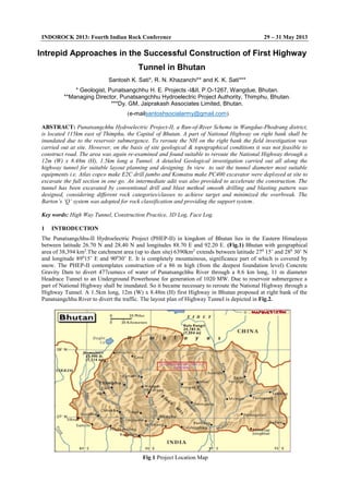
- 1. INDOROCK 2013: Fourth Indian Rock Conference 29 – 31 May 2013 Intrepid Approaches in the Successful Construction of First Highway Tunnel in Bhutan Santosh K. Sati*, R. N. Khazanchi** and K. K. Sati*** * Geologist, Punatsangchhu H. E. Projects -I&II, P.O-1267, Wangdue, Bhutan. **Managing Director, Punatsangchhu Hydroelectric Project Authority, Thimphu, Bhutan. ***Dy. GM, Jaiprakash Associates Limited, Bhutan. (e-mailsantoshsocialarmy@gmail.com) ABSTRACT: Punatsangchhu Hydroelectric Project-II, a Run-of-River Scheme in Wangdue-Phodrang district, is located 115km east of Thimphu, the Capital of Bhutan. A part of National Highway on right bank shall be inundated due to the reservoir submergence. To reroute the NH on the right bank the field investigation was carried out at site. However, on the basis of site geological & topographical conditions it was not feasible to construct road. The area was again re-examined and found suitable to reroute the National Highway through a 12m (W) x 8.48m (H), 1.5km long a Tunnel. A detailed Geological investigation carried out all along the highway tunnel for suitable layout planning and designing. In view to suit the tunnel diameter most suitable equipments i.e. Atlas copco make E2C drill jumbo and Komatsu make PC400 excavator were deployed at site to excavate the full section in one go. An intermediate adit was also provided to accelerate the construction. The tunnel has been excavated by conventional drill and blast method smooth drilling and blasting pattern was designed, considering different rock categories/classes to achieve target and minimized the overbreak. The Barton’s ‘Q’ system was adopted for rock classification and providing the support system. Key words: High Way Tunnel, Construction Practice, 3D Log, Face Log. 1 INTRODUCTION The Punatsangchhu-II Hydroelectric Project (PHEP-II) in kingdom of Bhutan lies in the Eastern Himalayas between latitude 26.70 N and 28.40 N and longitudes 88.70 E and 92.20 E. (Fig.1) Bhutan with geographical area of 38,394 km2 .The catchment area (up to dam site) 6390km2 extends between latitude 270 15’ and 280 30’ N and longitude 890 15’ E and 900 30’ E. It is completely mountainous, significance part of which is covered by snow. The PHEP-II contemplates construction of a 86 m high (from the deepest foundation level) Concrete Gravity Dam to divert 477cumecs of water of Punatsangchhu River through a 8.6 km long, 11 m diameter Headrace Tunnel to an Underground Powerhouse for generation of 1020 MW. Due to reservoir submergence a part of National Highway shall be inundated. So it became necessary to reroute the National Highway through a Highway Tunnel. A 1.5km long, 12m (W) x 8.48m (H) first Highway in Bhutan proposed at right bank of the Punatsangchhu River to divert the traffic. The layout plan of Highway Tunnel is depicted in Fig.2. Fig 1 Project Location Map
- 2. INDOROCK 2013: Fourth Indian Rock Conference 29 – 31 May 2013 Fig 3 Geological L- Section through Highway Tunnel 2 GEOLOGICAL SETTINGS Regionally the PHEP-II area is located within the Tethyan Belt of Bhutan Himalayas and at the proposed dam site; rocks of Sure/ Shumar Formation of Thimphu Group of Precambrian age are exposed. The rocks of Thimphu Group in general are characterized by coarse – grained quartzo-feldspathicbiotite-muscovite gneiss with bands of mica schist, quartzite and concordant veins of foliated leucogranitoid, migmatites with minor bands of amphibolites and marbles. Garnet porphyroblasts are also seen within these gneisses. 3 GOTECHNICAL CONSIDERATION AND LAYOUT PLANNING For the purpose of diverting traffic due to the reservoir submergence and stripping, excavation and treatment of right abutment of 86 m high concrete dam, a highway tunnel was provided. Geological and geotechnical evaluation of Highway Tunnel has been made based on the analysis of surface data and 3D Logging and Face logging during construction and geological data collected during the course of the investigations. During planning of tunnel layout and its portal vertical and horizontal cover criteria were considered and accordingly the highway tunnel alignment was proposed to have sufficient vertical and as well as lateral cover. The minimum vertical cover is ˜10m and the maximum is about ˜150m (Fig 3). Lateral cover was low at Northern portal is about 5m in initial reach. During designing of highway tunnel it is kept in mind that the alignment should be straight with smooth curve from Northern portal, the alignment of highway tunnel crossing the four power intake with vertical cover of 21m were considered. The slope of tunnel is 1:54.36 from Northern portal at RD 0 to RD 1000m after that it is 1:23.50 from RD 1100 to 1500m at Southern Portal. During Fig 2 Layout Plan Of Highway Tunnel
- 3. INDOROCK 2013: Fourth Indian Rock Conference 29 – 31 May 2013 Fig 4 Percentage of Expected and Actual Rock Class Encounter in Highway Tunnel construction it is felt that from 2 faces it is difficult to excavate the highway tunnel within scheduled time frame. An intermediate adit was proposed to facilitate and accelerating the excavation of the highway tunnel. 4 ANTICIPATED ROCK MASS QUALITY AND ROCK ALTERATION The expected / anticipating rock mass quality during investigation and planning of Highway Tunnel, is based on the surface mapping and rock outcrop exposed in the area and it vary due to geological surprises ie. Shear/fractured, faults, ground water inflow during construction. The rock mass along the alignment of Highway Tunnel has been subjected to three type of alteration that is generally developed along shear/fractured zones and influenced the strength of rock mass. The alterations also influence the strength and abrasivity of rock mass. The percentage of anticipated and actual rock mass condition encountered during construction is shown in Fig 4. 5 ANTICIPATED ROCK TYPE ITS CATEGORY AND EXCAVATION CONDITION The rock type along the tunnel alignment broadly divided in to three units: 1) Biotite Gneiss 2) Leucogranite 3) Pegmatite with Biotite Gneiss On the basis of litho tectonic characteristic and other influencing factor viz- excavation direction and orientation of discontinuities, ingress of ground water and overburden cover, the rock mass behavior evaluate the effects of influencing factors. The tunneling media have been classified in different units as given in Table 1. Table 1 Summary Different Units Encounter during Construction. Rock Mass Lithilogical Description Rock mass Behavior Deformation 1. Thinly bedded Biotite gneiss Spalling - 2. Biotite, hard and Massive Less jointed (Fresh) High overbreak, forming wedge In few cm 3. Leucigranite. Strong to very strong. Stable - 4. Biotite gneiss with intrusion of pegmatite. 2-3 m overbreak, forming wedges, rock fall. In few cm 5. Pegmatite cursed and fractured with bends of biotite gneiss High overbreak -do- The rock mass quality of the bedrocks for the entire tunnel alignment was anticipated on the basis of Q (Barton et al 1974, 1983, 1994) and RMR (Bieniawski et al 1978, 1989, Deere et al 1988) systems for the assessment The rock conditions expected during tunneling was Very good (5%) Fair (65%) Poor (30%) and actual encounter during construction is Fair (78%) and poor (22%) categories.
- 4. INDOROCK 2013: Fourth Indian Rock Conference 29 – 31 May 2013 6 GEOLOGY ALONG TUNNEL ALIGNMENT The tunnel Geological mapping was carried out by using face and 3-D geological log sheets at every advance. The rock strata encountered during tunnel alignment is mainly qurtzo-feldspathic gneiss with subordinate biotite schist bands and occasional patches of intrusive pegmatite. At the portal face, moderately jointed hard and massive quartzofelsphathic gnessies is exposed forming scarp face. The general trends of foliation vary from N700 E-S70W to N800E-S800 W with 200 -250 dip towards SE. On the basis of Barton’s Q system the rock strata has been categorized into Fair (78%) and poor (22%) categories. The important geological features observed during excavation and their characteristics are given in Table 2. Table 2 Characteristics of Important joints encountered in Highway Tunnel. S.No. Joint Set Strike Dip and Direction Spacing (in m) Persistence or Continuity Aperture/ Filling (mm) Feature 1. J1 N700 E-S70W to N800 E-S800 W 200 -250 : SE 0.2 to 0.5.m. > 20m. Tight to clay filled, 2 to 50mm open. Foliatio n joint 2. J2 N400 W-S400 E to N N600 W-S600 E 700 : N E 2 to 5m. 5m to 15m. Granular to clay filled. Joint 3. J3 N400 W-S400 E 600 -750 : SW 2 to 10 5m to 12m Generally 2mm, granular/crushed. Joint 4. J4 N100 W-S100 E 400 -800 : N800 E 1to 3m. 10 to 20m. Open upto 30mm Granular Joint 5 J5 E -W 300 to 600 :N 1to 2m. >10m Tight, sometime clay filled. Joint 6. J6 N600 E-S600 W to N800 E -S800 W 400 -600 : SE 5 to 50m >8m Clay/crushed Shear 7 EXCAVATION AND SUPPORT SYSTEM The excavation of Tunnel was started from outlet and Inlet end in January 2012, by heading (7.5m) and and benching (1.0m), methods. In view to accelerate the construction schedule tunneling methodology was reviewed and the excavation in full section was carried out by deploying Atlas copco make E2C boomer which is designed to drill horizontal hole upto 8.5m height. An intermediate adit was also made to speed up construction. In all respect the tunnel excavation was completed within 09 month in September 2012. The quantities of work executed during excavation are given in following Table 3. Table 3 Quantities of Works For Highway Tunnel. Quantities of Work Excavation 150118 m3 Shotcrete 4563.53m3 Rock Bolts 18720 RM Steel Ribs 280.80MT 8 DRILLING AND CHARGING PATTERN The major governing factors for any tunnel excavation and its stability are encountered Geological discontinuities drilling pattern and rock support system at every advance. During excavation of Highway Tunnel burn cut pattern of drilling was implemented. Special attention was given in drilling and charging of periphery holes, aligned horizontally @ 0.3m c/c spacing and charged alternatively with 25mm dia cartridge for control over brake. The drilling depth was considered on the basis of encountered rock categories i.e. 3.5m depth in fair to good categories and 2.0m depth in poor categories(fig.5 &6). In totality the average powder factor achieved at site was < 1.4 kg/m3 and the over brake was under 11%.
- 5. INDOROCK 2013: Fourth Indian Rock Conference 29 – 31 May 2013 X- SECTION OF COMMUNICATION TUNNEL FIGURE - 6a FOR CONTROL OVERBREAK PERIPHERY HOLES SHOULD BE CHARGED WITH ONLY PRIMERY CARTRIDEGE OF 40MM & REMANING CARTRIDGE OF 25MM/32MM. THROUGH DECKING SYSTEM MINIMUM EXCAVATION LINE UNCHARGED HOLE 0.80 0.80 0.80 0.30 0.30 0.30 0.60 0.85 0.85 0.85 PRIMER 40MM STEMMING CARTRIDGE 25MM DECKING(0.3M) N.E.D DECKING(0.3M) CARTRIDGE 25MM DECKING(0.3M) DECKING(0.3M) CARTRIDGE 25MM CARTRIDGE 25MM CARTRIDGE 25MM 1.002.50 0.85 3 2 1 0 44 4 4 R6.10 4 4 4 4 3 3 3 2 22 1 1 1 0.85 1.00 1.00 1.00 0.80 0.80 0.50 1.001.001.001.001.001.000.94 0.94 0.30 0.30 R6.10 8.48 6 6 6 6 6 6 6 6 6 6 6 6 6 5 5 5 5 55 5 5 5 5 7 7 8 7 7 7 7 8 8 88 8 8 8 8 9 9 9 9 9 9 10 10 10 10 10 1010 10 10 10 10 10 11 12 11 11 11 11 11 11 11 12 12 12 12 121212 12 12 12 12 12 15 15 15 15 15 15 15 15 15 15 1513 13 13 13 13 14 14 14 14 14 14 14 14 14 14 14 141414141414 14 14 14 14 14 14 14 14 14 14 14 14 13 13 13 1.00 11.23 0.55 0.98 1.00 17 2.38 0.50 13 0.50 13 0.62 1.00 1.00 1.00 1.00 1.00 1.00 1.00 1.00 1.00 1.00 0.62 16 16 16 16 16 16 16 16 16 16 1617 UNCHARGED HOLE FIGURE - 6c Face Area = 86.70 M 2 Expected Pull = 3.2 M. (average) Charge Factor = 1.39 Kg / M 3 DRILLING & CHARGING PATTERN OF CUT HOLES FIGURE - 6b 0.860.18 0.25 0.86 2.00 2.00 2 1 0 0.25 4 3 4 4 4 4 4 4 4 3 3 3 2 22 11 1 Fig 6a-c Drilling & Charging Pattern Adopted in Fair Rock Category X- SECTION OF COMMUNICATION TUNNEL FIGURE - 5a FIGURE - 5c 0.7001.300 PRIMER 32MM STEMMING CARTRIDGE 25MM N.E.D DECKING (0.3M) Face Area = 86.70 M 2 Expected Pull = 1.70 M. (average) Charge Factor = 1.27 Kg / M 3 UNCHARGED HOLE DRILLING & CHARGING PATTERN OF CUT HOLES FIGURE - 5b 0.860.18 0.25 0.86 2.00 2.00 2 1 0 0.25 4 3 0.30 0.30 3 2 1 0 44 4 4 R6.10 4 4 4 3 3 3 2 22 1 1 1 1.00 1.00 1.00 0.50 1.001.001.001.001.001.000.94 0.94 0.30 0.30 R6.10 8.48 5 5 5 5 55 5 5 5 5 13 14 1.00 11.23 0.55 0.98 1.00 16 2.38 0.50 0.50 0.62 1.00 1.00 1.00 1.00 1.00 1.00 1.00 1.00 1.00 1.00 0.62 15 15 15 15 15 15 15 15 15 15 1516 0.50 0.75 0.75 0.75 0.75 0.50 MINIMUM EXCAVATION LINE 0.30 6 6 6 6 6 6 6 6 6 6 6 67 7 7 7 7 7 8 8 8 88 8 8 8 9 9 9 9 9 9 10 10 10 10 101010 10 10 10 10 11 11 11 11 11 11 12 12 12 12 12 12 12 12 12 12 12 12 12 12 13 13 13 13 13 13 13 13 1313 13 13 13 13 13 13 13 13 13 14 14 14 14 14 14 14 14 14 14 FOR CONTROL OVERBREAK IInd ROW HOLES SHOULD BE CHARGED WITH ONLY PRIMARY CARTRIDEGE OF 32MM & REMAINING CARTRIDGE OF 25MM.THROUGH DECKING SYSTEM UNCHARGED HOLE 0.50 1.00 0.85 0.85 0.85 0.85 0.85 TO AVOID OVERBREAK & CAVITY THE HOLES WITH IN WEAK FEATURE/SHEAR SHALL BE LEFT UNCHARGED WHILE THE HARD PATCHES SHALL BE ALTERNATIVELY CHARGED AND REMOVED BY ONLY PRIMARY CARTRIDEGE. 0.30 4 4 4 4 4 4 4 3 3 3 2 22 11 1 4 Fig 5a-c Drilling & Charging Pattern Adopted in Poor Rock Category
- 6. INDOROCK 2013: Fourth Indian Rock Conference 29 – 31 May 2013 9 ROCK SUPPORT On the basis of encountered rock strata the support system was timely provided concurrent to excavation The immediate support consists of a steel fiber reinforced support (SFRS) shotcrete lining, 32mm diameter resin grouted rock bolts. The thickness of shotcrete is 75mm in rockmass II, 100mm in rockmass III, and 125mm in rockmass IV. The length of rockbolt is 6m in all rock mass class. The spacing of rockbolts is 1750*1750 staggered in rockmass II, 1500*1500 staggered in rockmass III and 1500*1000 staggered in rock mass IV. Steel rib installed in only rock mass class IV where Q value is >2, where required at a spacing of 500cm to 1000cm and in some overbrak reaches where overbreak is about 3 to 4m above crown. The final lining will be constituted of unreinforced concrete 500 mm thick. The excavation method and support system were selected accordingly to rock mass quality. The problem faced during excavation is mainly due to presence of low angle long continuity biotite schist bands associated damp condition. Such reaches were excavated by low charging getting short pull and supported with ISMB-250 Steel ribs with backfill concrete. 10 CONCLUSION After the Geological and Geotechnical investigation of the area and the results of site investigation indicate the rock mass condition have different characteristics. Complex geological and tectonic framework of the terrain required challenging excavation and construction procedures depending on site condition, according the layout of Highway Tunnel were finalized. During construction it is felt that from 2 faces it is difficult to excavate the highway tunnel within scheduled time frame. An intermediate adit was proposed to facilitate and accelerating the excavation of the highway tunnel. Drilling and Blasting pattern for Highway Tunnel were examine after every advanced and according rock mass class the pattern review and modified for better outcomes. On the basis of encountered rock strata the support system was timely provided concurrent to excavation and support system were installed as per rock mass class and site condition. ACKNOWLEDGEMENTS The Authors gratefully acknowledge the encouragement of the Engineers, Designers and those who are involved in preparing and presenting this paper. REFERENCES Barton N. (1983) “Application of Q-System and Index Test to Estimate Shear Strength and Deformability of Rock Masses”. Int. Symp Eng Geol and Und Const. Lisbon. Vol. II, pp II.51 – II.70. Barton, N., R. Lien R. & J. Lunde (1974) “Engineering Classification of Jointed Rock Masses for the Design of Tunnel Support”. Rock Mechanics, 6, p. 189-236. Barton, N. & E. Grimstad (1994) “The Q-System Following Twenty Years of Application in NMT Support Selection”. Felsbau 12 Nr. 6, pp. 428-436. Bieniawski Z.T. (1978) “Determining Rock Mass Deformability. Experience from Case Histories”. Int. J. Of Rock Mech and Min. Sci. Vol. 15 pp 237-242. Bieniawski Z.T. (1989) “Engineering Rock Mass Classifications”. Ed WILEY. New York, 252 pp.