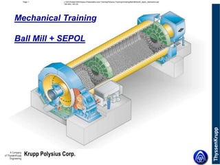
11. Krupp Polysius Corp.
L:DATADept150Polysius Presentation and TrainingPolysius TrainingGrindingBall Millbmill_sepol_mechanics.ppt
150 WEI, 140 CD
Page 11
Mill discharge
8.1 Discharge housing
8.2 Outlet cone
8.3 supporting structure
8.4 Inspection door
8.5 Seal
8.6 Connecting flange for exhaust air
8.7 Product discharge
12. Krupp Polysius Corp.
L:DATADept150Polysius Presentation and TrainingPolysius TrainingGrindingBall Millbmill_sepol_mechanics.ppt
150 WEI, 140 CD
Page 12
Discharge of a cement mill ( 3,6 x 11 m)
25. Krupp Polysius Corp.
L:DATADept150Polysius Presentation and TrainingPolysius TrainingGrindingBall Millbmill_sepol_mechanics.ppt
150 WEI, 140 CD
Page 25
Segments of adjustable diaphragms with lifters in different
positions
26. Krupp Polysius Corp.
L:DATADept150Polysius Presentation and TrainingPolysius TrainingGrindingBall Millbmill_sepol_mechanics.ppt
150 WEI, 140 CD
Page 26
Shifting the lifter
27. Krupp Polysius Corp.
L:DATADept150Polysius Presentation and TrainingPolysius TrainingGrindingBall Millbmill_sepol_mechanics.ppt
150 WEI, 140 CD
Page 27
Discharge Diaphragm
28. Krupp Polysius Corp.
L:DATADept150Polysius Presentation and TrainingPolysius TrainingGrindingBall Millbmill_sepol_mechanics.ppt
150 WEI, 140 CD
Page 28
Discharge diaphragm
6.1 Discharge diaphragm
framework
6.2 Lifter
6.3 Support
6.5 Slotted plate
6.10 segments of filler ring
6.11 Insulation
29. Krupp Polysius Corp.
L:DATADept150Polysius Presentation and TrainingPolysius TrainingGrindingBall Millbmill_sepol_mechanics.ppt
150 WEI, 140 CD
Page 29
6.1 Discharge diaphragm framework
6.3 Support
6.4 Support
6.6 End disc
6.7 Cone
6.8 Clamping ring
6.9 Grid
6.10 Segments of filler ring
6.11 Insulation
Discharge diaphragm
30. Krupp Polysius Corp.
L:DATADept150Polysius Presentation and TrainingPolysius TrainingGrindingBall Millbmill_sepol_mechanics.ppt
150 WEI, 140 CD
Page 30
POLYSIUS discharge diaphragm for ball mills
31. Krupp Polysius Corp.
L:DATADept150Polysius Presentation and TrainingPolysius TrainingGrindingBall Millbmill_sepol_mechanics.ppt
150 WEI, 140 CD
Page 31
Slide Shoe Bearing
37. Krupp Polysius Corp.
L:DATADept150Polysius Presentation and TrainingPolysius TrainingGrindingBall Millbmill_sepol_mechanics.ppt
150 WEI, 140 CD
Page 37
Thrust (fixed) bearing for axial guide
38. Krupp Polysius Corp.
L:DATADept150Polysius Presentation and TrainingPolysius TrainingGrindingBall Millbmill_sepol_mechanics.ppt
150 WEI, 140 CD
Page 38
Actual sealing design for bearing cover
• riding ring (mill shell)
• oil spray ring
• V- seal (open in 6 o´clock pos. for
discharge of oil and dust
• Y- seal with discharge holes in 6
o´clock position
• bearing cover
• additional cover with discharge
hole
• plate which prevents oil
contamination of concrete
foundation
• concrete foundation
inside
of
cover
44. Krupp Polysius Corp.
L:DATADept150Polysius Presentation and TrainingPolysius TrainingGrindingBall Millbmill_sepol_mechanics.ppt
150 WEI, 140 CD
Page 44
Self-aligning pinion
Permitted tilting: ± 10 mm
45. Krupp Polysius Corp.
L:DATADept150Polysius Presentation and TrainingPolysius TrainingGrindingBall Millbmill_sepol_mechanics.ppt
150 WEI, 140 CD
Page 45
Y
Z
X
COMBIFLEX 2000
46. Krupp Polysius Corp.
L:DATADept150Polysius Presentation and TrainingPolysius TrainingGrindingBall Millbmill_sepol_mechanics.ppt
150 WEI, 140 CD
Page 46
COMBIFLEX internal gears
Input shaft
Self-aligning
pinion
Direct contact with spur gear
47. Krupp Polysius Corp.
L:DATADept150Polysius Presentation and TrainingPolysius TrainingGrindingBall Millbmill_sepol_mechanics.ppt
150 WEI, 140 CD
Page 47
COMBIFLEX, view from mill side
• second stage: upper pinion
• intermediate shaft
• input shaft
48. Krupp Polysius Corp.
L:DATADept150Polysius Presentation and TrainingPolysius TrainingGrindingBall Millbmill_sepol_mechanics.ppt
150 WEI, 140 CD
Page 48
COMBIFLEX; arrangement of sole plates
49. Krupp Polysius Corp.
L:DATADept150Polysius Presentation and TrainingPolysius TrainingGrindingBall Millbmill_sepol_mechanics.ppt
150 WEI, 140 CD
Page 49
Oil Supply System
52. Krupp Polysius Corp.
L:DATADept150Polysius Presentation and TrainingPolysius TrainingGrindingBall Millbmill_sepol_mechanics.ppt
150 WEI, 140 CD
Page 52
Water Spray System
53. Krupp Polysius Corp.
L:DATADept150Polysius Presentation and TrainingPolysius TrainingGrindingBall Millbmill_sepol_mechanics.ppt
150 WEI, 140 CD
Page 53
1.0; 2.0 Injection lances
1.1 Protective air fan
1.2 Suction filter
1.3 Motor
1.4 Piping
1.5 Injection nozzle
2.5 Rotary connecting element
3.0 Feed-water regulator
3.1 Shut-off valve (water inlet)
3.2 Drain valve
3.3 Float switch
4 Change-over filter
5.0 Motor-pump unit
5.2 Coupling
5.3 Overflow valve
6 Contact pressure gauge
7 Drain and vent valves
8 Solenoid valve
9;12 Motorized valve for injection
lances 1.0; 2.0
10;13 Flowmeter for injection
lances 1.0; 2.0
11;14 Pressure gauge for injection
lances 1.0; 2.0
Water spray system
54. Krupp Polysius Corp.
L:DATADept150Polysius Presentation and TrainingPolysius TrainingGrindingBall Millbmill_sepol_mechanics.ppt
150 WEI, 140 CD
Page 54
3.0 Feed-water regulator
3.1 Shut-off valve (water inlet)
3.2 Drain valve
4 Change-over filter
5.0 Motor-pump unit
5.1 Motor
5.2 Coupling
5.3 Overflow valve
5.4 Drain plug
6 Contact pressure gauge
7 Drain and vent valves
8 Solenoid valve
9;12 Motorized valve for injection
lances 1.0; 2.0
10;13 Flowmeter for injection
lances 1.0; 2.0
11;14 Pressure gauge for injection
lances 1.0; 2.0
Water spray system
55. Krupp Polysius Corp.
L:DATADept150Polysius Presentation and TrainingPolysius TrainingGrindingBall Millbmill_sepol_mechanics.ppt
150 WEI, 140 CD
Page 55
Grinding Aid System
56. Krupp Polysius Corp.
L:DATADept150Polysius Presentation and TrainingPolysius TrainingGrindingBall Millbmill_sepol_mechanics.ppt
150 WEI, 140 CD
Page 56
Grinding Aid System
57. Krupp Polysius Corp.
L:DATADept150Polysius Presentation and TrainingPolysius TrainingGrindingBall Millbmill_sepol_mechanics.ppt
150 WEI, 140 CD
Page 57
Mechanical Training
SEPOL Separator
58. Krupp Polysius Corp.
L:DATADept150Polysius Presentation and TrainingPolysius TrainingGrindingBall Millbmill_sepol_mechanics.ppt
150 WEI, 140 CD
Page 58
Content
• Operation Description
• Separator Wear and Wear Protection
• SEPOL Inlet Damper
• SEPOL Internals
• Material Feed
• SEPOL Guide Vanes
• SEPOL Rotor
• Rotor Seal
• SEPOL Supports and Bearings
59. Krupp Polysius Corp.
L:DATADept150Polysius Presentation and TrainingPolysius TrainingGrindingBall Millbmill_sepol_mechanics.ppt
150 WEI, 140 CD
Page 59
Operation Description
60. Krupp Polysius Corp.
L:DATADept150Polysius Presentation and TrainingPolysius TrainingGrindingBall Millbmill_sepol_mechanics.ppt
150 WEI, 140 CD
Page 60
Operation description of the Polysius separator SEPOL NSV
and is transported
with the air to the
Cyclones or baghouse
Fineproduct passes rotor
Separating room
Adjustable air
inlet louvre
Disperion plate
Material feed
Motor
Rotor
Coarse material passes
rotor not and drops into
coarse collection cone
Coarse
material
back to mill
Material feed housing
Guide vanes
Tipping valve
61. Krupp Polysius Corp.
L:DATADept150Polysius Presentation and TrainingPolysius TrainingGrindingBall Millbmill_sepol_mechanics.ppt
150 WEI, 140 CD
Page 61
Operation description of SEPOL separator NSV
DISPERSION PLATE
AIR GUIDE PLATE
FEED BOX
REJECT CONE
ROTOR BLADES
GUIDE VANE
AIR INLET DUCT
CYCLONE
FRESH AIR OR CIRCULATING AIR
SEPARATOR FEED
SEPARATOR REJECTS
VENT AIR WITH FINES
62. Krupp Polysius Corp.
L:DATADept150Polysius Presentation and TrainingPolysius TrainingGrindingBall Millbmill_sepol_mechanics.ppt
150 WEI, 140 CD
Page 62
Operation description of SEPOL separator NSV without
cyclones
DISPERSION PLATE
AIR GUIDE PLATE
FEED BOX
REJECT CONE
ROTOR BLADES
GUIDE VANE
AIR INLET DUCT
FRESH AIR OR CIRCULATING AIR
SEPARATOR FEED
SEPARATOR REJECTS
VENT AIR WITH FINES
63. Krupp Polysius Corp.
L:DATADept150Polysius Presentation and TrainingPolysius TrainingGrindingBall Millbmill_sepol_mechanics.ppt
150 WEI, 140 CD
Page 63
Polysius SEPOL separator NSV
Protection tube for drive shaft
Dispersion plate
Baffle ring
Rotor blades
Inlet spiral
Guide vanes
Wear ring for guide vane support
Wear protection for bearing
suspension and grease lines
reject cone
Air / Product
Discharge Bend
64. Krupp Polysius Corp.
L:DATADept150Polysius Presentation and TrainingPolysius TrainingGrindingBall Millbmill_sepol_mechanics.ppt
150 WEI, 140 CD
Page 64
Separator Wear and Wear
Protection
65. Krupp Polysius Corp.
L:DATADept150Polysius Presentation and TrainingPolysius TrainingGrindingBall Millbmill_sepol_mechanics.ppt
150 WEI, 140 CD
Page 65
SEPOL NSV standard wear protection
Protection tube for drive shaft: mild steel
Lining of dispersion plate: ceramic mortar
Baffle ring: mild steel
Rotor blades: mild steel
Lining circumference of inlet spiral:
AR plate
Guide vanes: AR plate
Wear ring: compound steel plate
Bearing suspension and grease lines:
ceramic tube
Reject cone: completely of AR plate
Lining of air/product
discharge: ceramic mortar
66. Krupp Polysius Corp.
L:DATADept150Polysius Presentation and TrainingPolysius TrainingGrindingBall Millbmill_sepol_mechanics.ppt
150 WEI, 140 CD
Page 66
Wear - influencing factors
• Process parameter: - Velocity of particles
- Angle of impact
- Material load / bulk material mass
• Wear medium: - Shape of particles
- Hardness of particles
- Grain size
• Type of wear protection: - Hardness
- Surface
67. Krupp Polysius Corp.
L:DATADept150Polysius Presentation and TrainingPolysius TrainingGrindingBall Millbmill_sepol_mechanics.ppt
150 WEI, 140 CD
Page 67
Wear protection materials for SEPOL separator
• Cast basalt
• Ceramic mortar (DENSIT WEARSTOP M40, M60, M80)
• Al2O3 - ceramic (KALOCER or similar)
• Compound steel with hard facing (EURODUR)
• Wear resistant steel (CREUSABRO 4000)
68. Krupp Polysius Corp.
L:DATADept150Polysius Presentation and TrainingPolysius TrainingGrindingBall Millbmill_sepol_mechanics.ppt
150 WEI, 140 CD
Page 68
SEPOL NSV high-quality wear protection type “C”
Protection tube for drive shaft: compound steel plate
Lining of dispersion plate: ceramic mortar
Baffle ring: compound steel plate
Rotor blades: compound steel plate
Lining circumference of inlet spiral:
AR plate
Guide vanes: compound steel plate
Wear ring: compound steel plate
Bearing suspension and grease lines:
ceramic tube
Reject cone and lower housing:
ceramic mortar
Lining of air/product
discharge: ceramic mortar
69. Krupp Polysius Corp.
L:DATADept150Polysius Presentation and TrainingPolysius TrainingGrindingBall Millbmill_sepol_mechanics.ppt
150 WEI, 140 CD
Page 69
Standard wear protection for SEPOL with cyclones
Wear protection of separator:
See separate sheet
Cyclone ceiling:
Ceramic mortar
Cyclone cone:
Ceramic mortar
Duct work - clean gas side:
without waer liners
Rotor air fan:
Hard faced compound steel
Ceramic mortar
AR plate
Collecting duct - clean gas side:
without wear liners
Air fan housing:
AR plate
70. Krupp Polysius Corp.
L:DATADept150Polysius Presentation and TrainingPolysius TrainingGrindingBall Millbmill_sepol_mechanics.ppt
150 WEI, 140 CD
Page 70
Precautions to reduce SEPOL wear
• Early detection of wear, repair of damaged points, countermeasures
• Avoid junction points and uneveness in the lining surface (turbulences with
consequential erosion)
• Check the distribution of the material to be separated and improve,
if required and possible
• Check the air distribution (velocities) and adjust, if required
• Measure and reduce the air flow rate to the designed air flow rate,
if required
• Check the guide vane position: the angle of aperture should be between
15 and 30º
• Check the gap of the rotor seal at regular intervals and readjust to approx.
2mm (depending on the operating temperature and the size of the machine)
71. Krupp Polysius Corp.
L:DATADept150Polysius Presentation and TrainingPolysius TrainingGrindingBall Millbmill_sepol_mechanics.ppt
150 WEI, 140 CD
Page 71
SEPOL Inlet Damper
72. Krupp Polysius Corp.
L:DATADept150Polysius Presentation and TrainingPolysius TrainingGrindingBall Millbmill_sepol_mechanics.ppt
150 WEI, 140 CD
Page 72
SEPOL inlet damper
SEPOL air inlet spiral
Two horizontal guide
plates divide the SEPOL’s
upper housing into three
channels
Air though one channel can be throttled
in case of heavy wear at rotor blades
in this area
Air inlet damper:
all six valves can be adjusted individually.
They are normally fully open, but can be adjusted
in case of uneven air distribution
Separating air
(ambient or
recirculated air)
76. Krupp Polysius Corp.
L:DATADept150Polysius Presentation and TrainingPolysius TrainingGrindingBall Millbmill_sepol_mechanics.ppt
150 WEI, 140 CD
Page 76
SEPOL internals
Rotor shaft
Air inlet spiral
Guide vanes
Lower shaft bearing
Rotor blades
77. Krupp Polysius Corp.
L:DATADept150Polysius Presentation and TrainingPolysius TrainingGrindingBall Millbmill_sepol_mechanics.ppt
150 WEI, 140 CD
Page 77
SEPOL Guide Vanes
78. Krupp Polysius Corp.
L:DATADept150Polysius Presentation and TrainingPolysius TrainingGrindingBall Millbmill_sepol_mechanics.ppt
150 WEI, 140 CD
Page 78
SEPOL guide vanes
Above 40º
• vibrating of the guide vanes possible
• excessive wear at the rotor blades
• deposits of coarse material in the air inlet spiral
• oversized material might get dragged into finished product
15- 30º = normal guide vane position
25º = setting recommended by Polysius
5-15 º
clogging of guide vanes possible
wear at guide vanes possible
80. Krupp Polysius Corp.
L:DATADept150Polysius Presentation and TrainingPolysius TrainingGrindingBall Millbmill_sepol_mechanics.ppt
150 WEI, 140 CD
Page 80
SEPOL separator rotor
Rotor shaft
Guide vanes
Rotor blades
Dispersion plate
Material feed
Air inlet spiral
81. Krupp Polysius Corp.
L:DATADept150Polysius Presentation and TrainingPolysius TrainingGrindingBall Millbmill_sepol_mechanics.ppt
150 WEI, 140 CD
Page 81
SEPOL rotor
Parted rotor blades of compound steel plates with screwed support ring
Screwed support ring
Rotor blade fastening
Though base material
Hard facing layer,
approx. 63 HRC
83. Krupp Polysius Corp.
L:DATADept150Polysius Presentation and TrainingPolysius TrainingGrindingBall Millbmill_sepol_mechanics.ppt
150 WEI, 140 CD
Page 83
Rotor seal
Material discharge bend
(seal area adjusted
during erection)
Internal seal ring,
adjustable
External seal ring, adjustable
External labyrinth, replaceable
Rejects
“apron”
Rotor
84. Krupp Polysius Corp.
L:DATADept150Polysius Presentation and TrainingPolysius TrainingGrindingBall Millbmill_sepol_mechanics.ppt
150 WEI, 140 CD
Page 84
Rotor seal with seal air
Internal seal ring
Rotor seal area
External seal ring
Separator air and
product discharge
Seal air
Rotor blade
Rejects
“apron”
85. Krupp Polysius Corp.
L:DATADept150Polysius Presentation and TrainingPolysius TrainingGrindingBall Millbmill_sepol_mechanics.ppt
150 WEI, 140 CD
Page 85
Supply of seal air to the rotor seal
Rejects
“apron”
Seal air
Separator
air and
product
discharge
86. Krupp Polysius Corp.
L:DATADept150Polysius Presentation and TrainingPolysius TrainingGrindingBall Millbmill_sepol_mechanics.ppt
150 WEI, 140 CD
Page 86
SEPOL Supports and Bearings
87. Krupp Polysius Corp.
L:DATADept150Polysius Presentation and TrainingPolysius TrainingGrindingBall Millbmill_sepol_mechanics.ppt
150 WEI, 140 CD
Page 87
Lower SEPOL shaft and rotor bearing
Supporting steel Tube
Spring discs
Ceramic wear protection
Grease lines
Notice:
To extend lifetime, rotate the ceramic
tubes early enough when wear occurs!
88. Krupp Polysius Corp.
L:DATADept150Polysius Presentation and TrainingPolysius TrainingGrindingBall Millbmill_sepol_mechanics.ppt
150 WEI, 140 CD
Page 88
Lower support of guide vanes
Lower guide vane bearing,
segmented, adjustable
Segmented protective ring,
made of compound steel
Guide vanes tilted by 15º
Guide vane bearing pin
89. Krupp Polysius Corp.
L:DATADept150Polysius Presentation and TrainingPolysius TrainingGrindingBall Millbmill_sepol_mechanics.ppt
150 WEI, 140 CD
Page 89
Bearing and drive traverse
Material feed
Guide vanes pins for
bearing and adjustment
Drive support
90. Krupp Polysius Corp.
L:DATADept150Polysius Presentation and TrainingPolysius TrainingGrindingBall Millbmill_sepol_mechanics.ppt
150 WEI, 140 CD
Page 90
Question: SEPOL internals
91. Krupp Polysius Corp.
L:DATADept150Polysius Presentation and TrainingPolysius TrainingGrindingBall Millbmill_sepol_mechanics.ppt
150 WEI, 140 CD
Page 91
Maintenance and
Servicing Requirements
SEPOL Separator
92. Krupp Polysius Corp.
L:DATADept150Polysius Presentation and TrainingPolysius TrainingGrindingBall Millbmill_sepol_mechanics.ppt
150 WEI, 140 CD
Page 92
Necessary regular
checks
Frequency Irregularities and
their causes
Measures,
Remarks
1. Abnormal noises and
vibrations
Daily (local
checking,
vibration
monitoring)
Imbalance
- due to formation
of coating
- Clean
- Avoid static
electric charge
(by earthing)
2. Functioning of flap valves weekly - Incorrectly set
weights
- Jamming flaps
- Defective
bearing
- Readjust
3. Drive unit
- gear unit
- oil cooler
- motor
- shrunk on disk
- coupling
*)
*) acc. to separate machine manual or manufacturer’s instructions
93. Krupp Polysius Corp.
L:DATADept150Polysius Presentation and TrainingPolysius TrainingGrindingBall Millbmill_sepol_mechanics.ppt
150 WEI, 140 CD
Page 93
Necessary regular
checks
Frequency Irregularities and
their causes
Measures,
Remarks
4. Circulating air fan
- rotor
- inlet nozzle
*)
(Vibration
monitoring)
if necessary
Vibrations
- due to formation
of coating
- Improper
balancing
- Wear; setting
not concentric
See Point 1
- balance the rotor
- Replace wearing
part, adjust the
nozzle
5. Checking the lubrication
pipes for leakage
Every 2 weeks
(visual check)
6. Checking antifriction
bearings including
labyrinth seals for
sufficient supply of
lubricants
Every 2 weeks
(visual check;
temperature
monitoring)
7. Central lubrication system
(if existent)
*)
8. Cracks and leaks Every 4 weeks
(visual check)
Repair
*) acc. to separate machine manual or manufacturer’s instructions
94. Krupp Polysius Corp.
L:DATADept150Polysius Presentation and TrainingPolysius TrainingGrindingBall Millbmill_sepol_mechanics.ppt
150 WEI, 140 CD
Page 94
Necessary regular checks Frequency Irregularities
and their causes
Measures,
Remarks
9. Wear
- Lining of the upper
section of the housing
- Lining of the dispersion
plate
- Lining of the rejects cone
- Lining of the feed box
- Lining of the turning
fixture on the rotor shaft
- Lining of the cyclone
cover
- Lining of the cyclones
- Lining of the distributor
housing and the piping
- Wear protection of
lubrication pipe
- Wear protection of
tension rods
- Rotor blades
- Guide vane ring and
guide vanes
- Access ring
Every 4 weeks
(depends on the
wear attrition)
Repair or refurbish
as necessary.
Checking and
working inside the
separator must only
be done after the
unit has been
disconnected from
the electricity
supply.
95. Krupp Polysius Corp.
L:DATADept150Polysius Presentation and TrainingPolysius TrainingGrindingBall Millbmill_sepol_mechanics.ppt
150 WEI, 140 CD
Page 95
Necessary regular checks Frequency Irregularities
and their causes
Measures,
Remarks
10. Bolted connections for
prescribed tightening torque
Every 6 month
(for the 1st
commissioning
after 100
operating hours)
96. Krupp Polysius Corp.
L:DATADept150Polysius Presentation and TrainingPolysius TrainingGrindingBall Millbmill_sepol_mechanics.ppt
150 WEI, 140 CD
Page 96
Troubleshooting
SEPOL Separator
97. Krupp Polysius Corp.
L:DATADept150Polysius Presentation and TrainingPolysius TrainingGrindingBall Millbmill_sepol_mechanics.ppt
150 WEI, 140 CD
Page 97
Nr. Problem Cause Measures Note
1. Finished material
temperature too high
(danger of
hemihydrate formation)
Feed material
too hot
- Feed in fresh air before
separator (possibly
install fresh-air-pipe-
sockets)
- Try increasing the mill’s
aeration
- Inject water into the mill
Sufficient
dedusting is
necessary
(system fan and
system filter must
be sufficiently big)
2. Granulometric
distribution is too flat
Guide vane
ring is opened
too far
- set guide vanes more
tangentially
In steps of 5,
max 10
3. Granulometric
distribution is too steep
(water demand of
cement possibly too
high)
Excessive
tangential
setting of the
guide vanes
- set guide vanes more
radial
- Throttle the circulating
air fan or system fan
(lower the separator
efficiency)
In steps of 5,
max 10
98. Krupp Polysius Corp.
L:DATADept150Polysius Presentation and TrainingPolysius TrainingGrindingBall Millbmill_sepol_mechanics.ppt
150 WEI, 140 CD
Page 98
Nr. Problem Cause Measures Note
Ineffective
sealing
between rotor
and fines
discharge
- Re-adjust sealing ring
4. Oversize grains in
finished material
Leaky
inspection door
in finished
product outlet
- Seal the door Suction due to
pressure
difference
between finished
material pipe and
tailings cone
High material
moisture
content (e.g.
gypsum,
admixtures)
- Reduce moisture
content of material
- Additional heating
5. Coatings on the rotor
blades
Static electric
charge
- Earth the separator
6. High water demand of
the product
Granulometric
distribution too
steep
- Adjust guide vanes Flatter curve in
RRS diagram
(see Point 3)
99. Krupp Polysius Corp.
L:DATADept150Polysius Presentation and TrainingPolysius TrainingGrindingBall Millbmill_sepol_mechanics.ppt
150 WEI, 140 CD
Page 99
Nr. Problem Cause Measures Note
Unfavorable
design of the
inlet cone
- Alter the inlet cone
(possibly correct the
cone collar to suit the
flow of material)
Excessive flow
speed of the
separator feed
material in the
feed through
- Throttle conveying air
in the feed through
7. Poor distribution of the
separator feed material
Wear on
distribution
plate
- Repair distribution plate
Insufficient
dedusting
- Open damper before
dedusting fan wider
Deduster and fan
must be adequate
8. Overpressure in
separator (dust
formation)
Fresh air flap
opened too
wide
- Throttle fresh-air flap Deduster and fan
must be adequate
100. Krupp Polysius Corp.
L:DATADept150Polysius Presentation and TrainingPolysius TrainingGrindingBall Millbmill_sepol_mechanics.ppt
150 WEI, 140 CD
Page 100
Nr. Problem Cause Measures Note
9. Excessive negative
pressure in separator
Damper before
dedusting fan
open too wide
- Throttle dedusting air Set negative
pressure before
separator to the
point where dust
is just prevented
from emerging at
the separator
feed (1-2 mbar)
- Improve the process
technological
environment (sufficient
aeration of mill etc)
Separator feed
material
contains
agglomerated
constituents
- Add grinding aid at the
mill
10. Unfavorable course of
Tromp curve (high
material bypass)
Insufficient
volume of
separating air
- Install fresh air flap Take the fan
capacity into
account
101. Krupp Polysius Corp.
L:DATADept150Polysius Presentation and TrainingPolysius TrainingGrindingBall Millbmill_sepol_mechanics.ppt
150 WEI, 140 CD
Page 101
Nr. Problem Cause Measures Note
1. Finished material
temperature too high
(danger of
hemihydrate formation)
Feed material
too hot
- Feed in fresh air before
separator (possibly
install fresh-air-pipe-
sockets)
- Try increasing the mill’s
aeration
- Inject water into the mill
Sufficient
dedusting is
necessary
(system fan and
system filter must
be sufficiently big)
2. Granulometric
distribution is too flat
Guide vane
ring is opened
too far
- set guide vanes more
tangentially
In steps of 5,
max 10
3. Granulometric
distribution is too steep
(water demand of
cement possibly too
high)
Excessive
tangential
setting of the
guide vanes
- set guide vanes more
radial
- Throttle the circulating
air fan or system fan
(lower the separator
efficiency)
In steps of 5,
max 10