This document outlines troubleshooting procedures for various problems that can occur in a press area. It lists 19 issues including abnormal readings, uneven pressing, track gauge problems, overheating oil, chuck and unchuck malfunctions, measuring calliper issues, hydraulic pump failures, chip accumulation, moisture in air lines, platform height, roofing needs, wheel chuck modifications, stopper additions, lubrication systems, cracked ram cylinders, broken wheel stoppers, overloaded cushioning cylinders, and a broken drive rod. For each problem, it provides steps to check components and introduces solutions that were implemented.
Passive Air Cooling System and Solar Water Heater.ppt
4. hyudralic press machine
1. TROUBLE SHOOTING PROBLEM IN PRESS AREATROUBLE SHOOTING PROBLEM IN PRESS AREA
Sl
No
TROUBLE TROUBLE SHOOTING FIGURE
1 How to avoid HT ,
LT , rejections ,
graph / abnormal
etc .
a) To check Finish of
Bore
b) Positive taper to be
ensured (0.06 mm) on
finished bore
c) Graph – Pressure
transducer to be
checked for oil supply
d) Data cable to be
checked
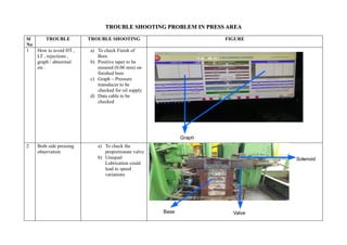
2 Both side pressing
observation
a) To check the
proportionate valve
b) Unequal
Lubrication could
lead to speed
variations
Graph
Base Valve
Solenoid
2. 3 Track gauge
problem
a) Wheel gripping is not
taking place
b) Check encoder
working
4 Oil too hot signal a) Higher than ambient
hot water temperature
in inlet line
b) Heat exchanger to be
checked
c) Check for relief valve
problems
Wheel pad
Stopper
End cover
Heat exchange
3. 5 Chuck and un chuck
problems
Check for brakes function
6 Tool movement
problem – tool not
opening
a) Electrical wiring ,
encoder signal,
coupling to be checked
b) Data cable to be
checked
Spring
Brake
Data cable
4. 7 Measuring – calliper
not working
a) Electrical problem ,
check Junction box for
burn
b) Linear scale cable
checks
c) Cylinder seals
leakage , external or
internal
8 Hydraulic pump not
working
Sound in the pump
Overheating of
pump
Pump starvation
etc..
a) Oil filters to be
checked
b) Level of the tank to be
checked
c) Oil contamination in
the oil
d) Relief valve to be
checked
Piston
Seal
Valve base
Solenoid
Valve
5. 9 As chips
accumulated near
wheel lift No.2,
which cause
restriction to
movement.
To avoid metal plate or
Torplin to be provided.
10 As moisture is
coming from main
air line, which
causes damages to
pneumatic valves,
cylinders.
To over come this, Air
drier and automatic
system to be
introduced.
Axle lifter
Hyudralic cylinder
6. 11 Height of platform
near wheel loader –
unloader to be
reduced.
To attend breakdowns
comfortably.
12 Near East borer roof
to be provided.
For safety of operators.
Wheel loader
Fencing
7. 13 Wheel chuck
bottom pad to be
modified.
To avoid thread failing
of mounting bolts.
14 Pneumatic operated
stopper
To be introduced
before wheel conveyor
& wheel lift No.1.
Wheel pad
Stopper
8. 15 Abutement side for
centre jib
lubrication.
Introduced lubrication system.
16 SMTC press ram
side axle cantering
unit piston rod was
cracked & hydraulic
oil leakage.
To over come this new piston
rod manufactured and fitted to
machine (welded).
Ram cylinder
Hydraulic pipe
9. 17 SMTC press, as
found East side
Wheel stopper unit
bracket brokened
frequently.
To avoid this modified wheel
stopper bracket introduced.
18 Cushioning cylinder
piston breaking
frequently while
wheel set moved
towards ram side
literally due to over
load.
To avoid over load as wheel
has score marks on axle brass
pads are provided found
working satisfactorily.
Spring Brake
Axle loader
10. 19 Wheel load and
unloader main drive
rod breaking at the
top stop due to over
load.
To avoid brass plate provided.
Base pad