SlideShare a Scribd company logo
1 of 18
Download to read offline
Service Information
Document Title: Function Group: Information Type: Date:
Description 210 Service Information 2014/5/29
Profile:
Description
Loader L330C is provided with a type TD164KAE engine.
The engine is a straight, six-cylinder, direct-injection, diesel engine with turbo charging and charge-air cooler (Intercooler).
TD164KAE is a low-emission engine provided with an engine speed controlled injection timing device.
The cylinder bore is 144 mm (5.669 in) and the stroke 165 mm (6.496 in) which provides a total displacement of 16.12 litres
(983 in3).
The engine type designation and serial numbers are stamped in on the cylinder block face for the cylinder heads, see Fig.
Figure 1
Engine type and serial numbers
The applicable output and torque curves for the engine are shown in Fig.
Figure 2
Output and torque curves
Service Information
Document Title: Function Group: Information Type: Date:
Engine, checking function 210 Service Information 2014/5/29
Profile:
Engine, checking function
Testing for possible causes
1 First check:





Fluid levels
Control and warning lamps
Instruments
Battery voltage
Fuses (correct rating)
2 Separate systems:
 If two or more systems, and/or circuits work together.
CHECK THE SYSTEMS/CIRCUITS INDIVIDUALLY.
3 If the machine has poor pulling power, the fault may be in the engine, torque converter or transmission;
Then check the stall speed, see Specifications.


If the engine stall speed is within the prescribed values, the fault can be found in the transmission or torque
converter.
If the engine stall speed is low, check according to point 4.
4 Checking engine














Checking oil and coolant respectively, discolouration, smell, etc.
Checking exhaust pipe (inside sticky)
Checking air filter and turbocharger.
If the engine runs unevenly (imbalance–noise)
Checking excess pressure in header tank.
Crankcase ventilation (excess pressure/clogged)
Oil dipstick, remove (excess pressure)
Exhaust smoke (discolouration, smell).
Bleed the fuel system.
Check engine speed.
Check feed pressure (before and after filter).
Carry out compression test (if incorrect repeat using oil).
Check the injectors.
Check injection angle (injection timing).
Service Information
Document Title: Function Group: Information Type: Date:
Engine, fitting 210 Service Information 2014/5/29
Profile:
Engine, fitting
Op nbr 21072
999 3590 Gear
Ratchet block 750 kg (1654 lb), 4 pcs
Lifting sling 2 m (6.5 ft), 4 pcs
Lifting sling 4 m (13 ft)
Lifting sling 3 m (10 ft)
Shackle 7/16", 2 pcs
Shackle 5/8", 2 pcs
Shackle adapted for lifting device
Pipe Ø50 mm (1.97 in), length 800 mm (31 in), thickness of material approx. 4 mm (0.16 in)
1. Check that the bushing for the bearing stud and the ring gear are positioned in the flywheel.
2. Fit a new seal to the torque converter connection flange, also apply sealing compound type black silicone on the
connecting flange.
3. Position a piece of board or sheet metal against the radiator so that it will not be damaged, see Fig. [Invalid
linktarget]
4. Connect a hoist to the engine and lift in the engine according to Fig. [Invalid linktarget]
Incline the engine so that the bearing stud on the torque converter does not catch in the flywheel housing.
5. Connect the hose for draining the oil to the oil sump.
6. Place the engine horizontally and move it against the torque converter.
Rotate the flywheel according to Fig. so that the teeth enter engagement.
Figure 1
Rotating flywheel
1. 999 3590
CAUTION
Make sure that the rubber boots at the inlet manifold of the hydraulic oil pumps are under load.
7. Fit the bolted joint flywheel housing–torque converter and clamp the cable harnesses with the upper bolts.
Tightening torque 60 N m (44 lbf ft).
8. Fit the front right engine mounting.
Tightening torque 220 N m (162 lbf ft).
9. Position the rubber dampers for the engine mountings together with washers and bolts.
Lower the engine and at the same time gradually take the load off the ratchet blocks in which the torque converter
is suspended.
10. Tighten the bolts for the rubber dampers of the engine mountings.
Tightening torque 350 N m (258 lbf ft).
11. Connect the coolant pipe between coolant pump and transmission oil cooler. Use a new O-ring.
NOTE!
Connect the coolant pump end first.
12. The following applies to machines equipped with air conditioning:
Bolt on the AC compressor and tension the drive belt.
Fit the member for the lower bracket of the condenser and bolt on the condenser.
CAUTION
Do not bend the hoses so that they break. A broken hose must be changed.
13. Connect the following on the right side of the engine:




Cable harness and cable connections to the alternator, temperature sensor and tank sensor.
Cable connections to air conditioning pressure monitor (if fitted).
The hoses to the cab heater.
The engine part-flow oil filter.
14. Fit the pipe between the transmission oil cooler and the thermostat housing.
15. Fit the pipe between the lower connection on the radiator and the thermostat housing.
16. Connect the following on the left side of the engine:







Cable harness and cable connections to starter motor.
The fuel system prefilter.
The fuel lines to the fuel pump.
The bracket with the engine speed control.
The control cable to the control arm on the injection pump.
The bracket and relay for the air preheater.
The bracket with the transmission oil filters.
17. Position the superstructure according to Fig.
Figure 2
Fitting superstructure
Lift according to Fig.
Figure 3
Position of lifting points
1.
2.
Sling 4 metres (13 ft)
Shackle 7/16"
At the same time connect the hose for the turbocharger.
Adjust the height of the superstructure with the required number of washers under the rubber dampers.
18. Connect the following:




The hoses to the header tank.
The electrical lead to the air filter indicator.
The coolant hoses to the engine.
The pipe to the exhaust side of the turbocharger.
19. Fill with coolant and engine oil.
20. Disconnect the frame joint lock.
21. Bleed the fuel system.
Start the engine and check that there are no leaks.
22. Fit the cover above the hydraulic tank and the side plates.
Service Information
Document Title: Function Group: Information Type: Date:
Engine, removing 210 Service Information 2014/5/29
Profile:
Engine, removing
Op nbr 21070
E 1034 Nipple
Ratchet block 1500 kg (3308 lb)
Ratchet block 750 kg (1654 lb), 3 pcs
Sling, 2 m (6.5 ft), 4 pcs
Sling, 3 m (10 ft)
Sling, 4 m (13 ft)
Shackle 7/16", 2 pcs
Shackle 5/8", 2 pcs
Shackle adapted for lifting device
Nipple part no. 11 054 659
Pipe Ø50 mm (2 in), length 800 mm (31 in), thickness of material 4 mm (0.16 in)
1. Secure the frame joint with the frame joint lock.
2. Turn off the battery disconnect switch.
3. Drain the coolant, using E1034.
Drain the engine oil using nipple part. no. 11054659.
WARNING
There is a danger of scalding when removing the cap for the header tank (radiator cap), as the cooling
system is pressurised when hot.
4. Remove the side plates and the cover above the hydraulic tank and open the side covers.
5. Detach the following connections to the superstructure:





The hoses from the header tank.
The electrical lead from the air filter indicator.
The turbocharger inlet hose.
Hoses from the engine.
The pipe from the turbocharger exhaust side.
6. Remove all attaching bolts (4 pcs) for the superstructure. Note the number of washers on the rubber dampers on
which the superstructure stands.
The weight of the superstructure is approx. 340 kg (750 lb).
7. Connect a hoist according to Fig.
Figure 1
Position of lifting points
1.
2.
Sling 4 metres (13 ft)
Schackle 7/16"
8. Lift away the superstructure according to Fig.
Figure 2
Removing superstructure
9. For machines equipped with air conditioning, the following applies:
– Remove the condenser attaching bolts.
Position the condenser according to Fig
Figure 3
Position of condenser
CAUTION
Do not loosen the hose connections to the condenser.
NOTE!
Do not bend the hoses, so that they break. A broken hose must be changed.
Remove the member for the lower brackets of the condenser.
– Remove the compressor drive belt and attaching bolts.
CAUTION
Do not loosen the hose connections to the compressor.
Position the compressor according to Fig.
Figure 4
Position of compressor
NOTE!
Do not bend the hoses so that they break. A broken hose must be changed.
10. Detach the following from the right side of the engine:



Cable harness.
The hoses to the cab heater.
The engine part-flow filter.
11. Remove the coolant pipe from the thermostat housing connecting pipe.
12. Remove the coolant pipe from the lower connection on the radiator.
13. Loosen the transmission oil cooler at the front end and detach the coolant pipe.
Position the pipe under the transmission oil cooler.
14. Detach the following from the left side of the engine:







Cable harness and cable connections to starter motor.
The fuel system prefilter.
The fuel lines from the fuel pump.
The bracket for the engine speed control.
The control cable from the control arm on the injection pump.
The bracket and relay for the air preheater.
The bracket for the transmission filters from the frame.
15. Remove the engine mounting bolts at the rubber dampers.
NOTE!
If the machine is provided with secondary steering, it may be necessary to disconnect certain hoses in order to
improve accessibility.
16. Suspend the torque converter against the hydraulic tank according to Fig.
Figure 5
Suspension of torque converter
1.
2.
3.
Pipe length 0.8 metre (31 in)
Ratchet block 750 kg (1654 lb)
Sling 2 m (6.5 ft)
4. Lifting eye 3/4" UNC
17. Suspend the hydraulic pumps according to Fig.
Figure 6
Suspending hydraulic pumps
1. Sling 4 m
Figure 7
Suspending hydraulic oil pumps
1.
2.
Sling 2 m (6.5 ft)
Ratchet block 750 kg (1654 lb)
18. Detach the hose from the flywheel housing.
19. Connect a hoist to the engine, see Fig. [Invalid linktarget]
The engine weight is approx. 1430 kg (3153 lb).
20. Lift the engine so that the rubber dampers are unloaded. Tension the ratchet blocks which are connected to the
torque converter.
CAUTION
Make sure that the rubber boots on the inlet pipes do not have to take any load.
Remove the washers and the rubber dampers.
Figure 8
emoving engine
1.
2.
3.
4.
Sling 3 m (10 ft)
Ratchet block 1.5 tonnes (3307 lb)
Shackle 5/8", 2 pcs
Shackle adapted for the lifting device
21. Remove the front right engine mounting.
22. Position a protective board or metal sheet against the radiator by the belt pulley. See Fig.
Figure 9
Guard for radiator
1. Piece of board
23. Remove the bolts between the flywheel housing and torque converter housing. Press the parts apart according to
Fig.
Figure 10
Pressing flywheel housing and torque converter housing apart
1. Puller bolt, upper (lower botl is positioned diametrically opposite)
NOTE!
The figure shows the upper puller bolt. The lower puller bolt is positioned diametrically opposite the upper one.
24. Pull the engine rearward and lift it approx. 20 cm (8 in)
CAUTION
The bearing stud in the torque converter.
25. Detach the hose from the draining nipple under the engine oil sump.
26. Incline the engine according to Fig. so that the bearing stud on the torque converter will go free when the unit is
lifted further.
Figure 11
Position of engine to clear the torque converter bearing stud.
27. Remove the engine.
Suggest:
If the above button click is invalid.
Please download this document
first, and then click the above link
to download the complete manual.
Thank you so much for reading
Service Information
Document Title: Function Group: Information Type: Date:
Description 211 Service Information 2014/5/29
Profile:
Description
The engine has one separate cast iron cylinder head for each cylinder with replaceable guides and valves seat inserts. There
are four valves per cylinder (two inlet and two exhaust valves).
Inlet and exhaust ducts open out on either side of the cylinder head.
The injector is vertically positioned straight above the piston crown centre in thin replaceable copper sleeves which are
directly cooled by circulating coolant.
Figure 1
Cylinder head
Service Information
Document Title: Function Group: Information Type: Date:
Cylinder block 212 Service Information 2014/5/29
Profile:
Cylinder block
The cylinder block is made of cast iron and is cast in one piece and provided with "wet" replaceable cylinder liners.
The significance of "wet" cylinder liners is that they are in direct contact with the coolant.
The crankshaft is journalled in the cylinder block in replaceable, pre-finished main bearing shells. The centre main bearing
location is also provided with a thrust bearing.
The main bearing caps are made of nodular iron. They are, in addition to the usual bolted joint, also connected to the sides
of the cylinder block through reinforcing plates in order to contribute to a lower sound level.
Figure 1
Cylinder block

More Related Content

Similar to Volvo L330C LL (L330CLL) Wheel Loader Service Repair Manual Instant Download.pdf

Volvo L330E Wheel Loader Service Repair Manual Instant Download.pdf
Volvo L330E Wheel Loader Service Repair Manual Instant Download.pdfVolvo L330E Wheel Loader Service Repair Manual Instant Download.pdf
Volvo L330E Wheel Loader Service Repair Manual Instant Download.pdffapanhe306271
 
Volvo A30C Articulated Dump Truck Service Repair Manual Instant Download.pdf
Volvo A30C Articulated Dump Truck Service Repair Manual Instant Download.pdfVolvo A30C Articulated Dump Truck Service Repair Manual Instant Download.pdf
Volvo A30C Articulated Dump Truck Service Repair Manual Instant Download.pdff8iosedkdm3e
 
Volvo A30C Articulated Dump Truck Service Repair Manual Instant Download.pdf
Volvo A30C Articulated Dump Truck Service Repair Manual Instant Download.pdfVolvo A30C Articulated Dump Truck Service Repair Manual Instant Download.pdf
Volvo A30C Articulated Dump Truck Service Repair Manual Instant Download.pdffijsekkkdmdm3e
 
Volvo A30C Articulated Dump Truck Service Repair Manual Instant Download.pdf
Volvo A30C Articulated Dump Truck Service Repair Manual Instant Download.pdfVolvo A30C Articulated Dump Truck Service Repair Manual Instant Download.pdf
Volvo A30C Articulated Dump Truck Service Repair Manual Instant Download.pdfran4gangbi
 
Volvo A30C Articulated Dump Truck Service Repair Manual Instant Download.pdf
Volvo A30C Articulated Dump Truck Service Repair Manual Instant Download.pdfVolvo A30C Articulated Dump Truck Service Repair Manual Instant Download.pdf
Volvo A30C Articulated Dump Truck Service Repair Manual Instant Download.pdfzu0582kui
 
Volvo A30C Articulated Dump Truck Service Repair Manual Instant Download.pdf
Volvo A30C Articulated Dump Truck Service Repair Manual Instant Download.pdfVolvo A30C Articulated Dump Truck Service Repair Manual Instant Download.pdf
Volvo A30C Articulated Dump Truck Service Repair Manual Instant Download.pdflunrizan628
 
Volvo A30C Articulated Dump Truck Service Repair Manual Instant Download.pdf
Volvo A30C Articulated Dump Truck Service Repair Manual Instant Download.pdfVolvo A30C Articulated Dump Truck Service Repair Manual Instant Download.pdf
Volvo A30C Articulated Dump Truck Service Repair Manual Instant Download.pdfqiuqiaoxi0
 
Volvo A30C Articulated Dump Truck Service Repair Manual Instant Download.pdf
Volvo A30C Articulated Dump Truck Service Repair Manual Instant Download.pdfVolvo A30C Articulated Dump Truck Service Repair Manual Instant Download.pdf
Volvo A30C Articulated Dump Truck Service Repair Manual Instant Download.pdfnie7140zhuang
 
Volvo A30C Articulated Dump Truck Service Repair Manual Instant Download.pdf
Volvo A30C Articulated Dump Truck Service Repair Manual Instant Download.pdfVolvo A30C Articulated Dump Truck Service Repair Manual Instant Download.pdf
Volvo A30C Articulated Dump Truck Service Repair Manual Instant Download.pdffapanhe306271
 
Volvo A30C Articulated Dump Truck Service Repair Manual Instant Download.pdf
Volvo A30C Articulated Dump Truck Service Repair Manual Instant Download.pdfVolvo A30C Articulated Dump Truck Service Repair Manual Instant Download.pdf
Volvo A30C Articulated Dump Truck Service Repair Manual Instant Download.pdfmanchao854
 

Similar to Volvo L330C LL (L330CLL) Wheel Loader Service Repair Manual Instant Download.pdf (10)

Volvo L330E Wheel Loader Service Repair Manual Instant Download.pdf
Volvo L330E Wheel Loader Service Repair Manual Instant Download.pdfVolvo L330E Wheel Loader Service Repair Manual Instant Download.pdf
Volvo L330E Wheel Loader Service Repair Manual Instant Download.pdf
 
Volvo A30C Articulated Dump Truck Service Repair Manual Instant Download.pdf
Volvo A30C Articulated Dump Truck Service Repair Manual Instant Download.pdfVolvo A30C Articulated Dump Truck Service Repair Manual Instant Download.pdf
Volvo A30C Articulated Dump Truck Service Repair Manual Instant Download.pdf
 
Volvo A30C Articulated Dump Truck Service Repair Manual Instant Download.pdf
Volvo A30C Articulated Dump Truck Service Repair Manual Instant Download.pdfVolvo A30C Articulated Dump Truck Service Repair Manual Instant Download.pdf
Volvo A30C Articulated Dump Truck Service Repair Manual Instant Download.pdf
 

More from fijsekkkdmdm3e

Volvo L150F Wheel Loader Service Repair Manual Instant Download.pdf
Volvo L150F Wheel Loader Service Repair Manual Instant Download.pdfVolvo L150F Wheel Loader Service Repair Manual Instant Download.pdf
Volvo L150F Wheel Loader Service Repair Manual Instant Download.pdffijsekkkdmdm3e
 
Volvo L150E Wheel Loader Service Repair Manual Instant Download.pdf
Volvo L150E Wheel Loader Service Repair Manual Instant Download.pdfVolvo L150E Wheel Loader Service Repair Manual Instant Download.pdf
Volvo L150E Wheel Loader Service Repair Manual Instant Download.pdffijsekkkdmdm3e
 
Volvo L250G Wheel Loader Service Repair Manual Instant Download.pdf
Volvo L250G Wheel Loader Service Repair Manual Instant Download.pdfVolvo L250G Wheel Loader Service Repair Manual Instant Download.pdf
Volvo L250G Wheel Loader Service Repair Manual Instant Download.pdffijsekkkdmdm3e
 
Volvo L180G Wheel Loader Service Repair Manual Instant Download.pdf
Volvo L180G Wheel Loader Service Repair Manual Instant Download.pdfVolvo L180G Wheel Loader Service Repair Manual Instant Download.pdf
Volvo L180G Wheel Loader Service Repair Manual Instant Download.pdffijsekkkdmdm3e
 
Volvo L180G HL (L180GHL) Wheel Loader Service Repair Manual Instant Download.pdf
Volvo L180G HL (L180GHL) Wheel Loader Service Repair Manual Instant Download.pdfVolvo L180G HL (L180GHL) Wheel Loader Service Repair Manual Instant Download.pdf
Volvo L180G HL (L180GHL) Wheel Loader Service Repair Manual Instant Download.pdffijsekkkdmdm3e
 
Volvo L220D Wheel Loader Service Repair Manual Instant Download.pdf
Volvo L220D Wheel Loader Service Repair Manual Instant Download.pdfVolvo L220D Wheel Loader Service Repair Manual Instant Download.pdf
Volvo L220D Wheel Loader Service Repair Manual Instant Download.pdffijsekkkdmdm3e
 
Volvo L180F Wheel Loader Service Repair Manual Instant Download.pdf
Volvo L180F Wheel Loader Service Repair Manual Instant Download.pdfVolvo L180F Wheel Loader Service Repair Manual Instant Download.pdf
Volvo L180F Wheel Loader Service Repair Manual Instant Download.pdffijsekkkdmdm3e
 
Volvo L90F Wheel Loader Service Repair Manual Instant Download.pdf
Volvo L90F Wheel Loader Service Repair Manual Instant Download.pdfVolvo L90F Wheel Loader Service Repair Manual Instant Download.pdf
Volvo L90F Wheel Loader Service Repair Manual Instant Download.pdffijsekkkdmdm3e
 
Volvo L150G Wheel Loader Service Repair Manual Instant Download.pdf
Volvo L150G Wheel Loader Service Repair Manual Instant Download.pdfVolvo L150G Wheel Loader Service Repair Manual Instant Download.pdf
Volvo L150G Wheel Loader Service Repair Manual Instant Download.pdffijsekkkdmdm3e
 
Volvo L180E Wheel Loader Service Repair Manual Instant Download.pdf
Volvo L180E Wheel Loader Service Repair Manual Instant Download.pdfVolvo L180E Wheel Loader Service Repair Manual Instant Download.pdf
Volvo L180E Wheel Loader Service Repair Manual Instant Download.pdffijsekkkdmdm3e
 
Volvo MC60B Skid Steer Loader Service Repair Manual Instant Download.pdf
Volvo MC60B Skid Steer Loader Service Repair Manual Instant Download.pdfVolvo MC60B Skid Steer Loader Service Repair Manual Instant Download.pdf
Volvo MC60B Skid Steer Loader Service Repair Manual Instant Download.pdffijsekkkdmdm3e
 
Volvo L180F HL (L180FHL) Wheel Loader Service Repair Manual Instant Download.pdf
Volvo L180F HL (L180FHL) Wheel Loader Service Repair Manual Instant Download.pdfVolvo L180F HL (L180FHL) Wheel Loader Service Repair Manual Instant Download.pdf
Volvo L180F HL (L180FHL) Wheel Loader Service Repair Manual Instant Download.pdffijsekkkdmdm3e
 
Volvo L70G Wheel Loader Service Repair Manual Instant Download.pdf
Volvo L70G Wheel Loader Service Repair Manual Instant Download.pdfVolvo L70G Wheel Loader Service Repair Manual Instant Download.pdf
Volvo L70G Wheel Loader Service Repair Manual Instant Download.pdffijsekkkdmdm3e
 
Volvo L330D Wheel Loader Service Repair Manual Instant Download.pdf
Volvo L330D Wheel Loader Service Repair Manual Instant Download.pdfVolvo L330D Wheel Loader Service Repair Manual Instant Download.pdf
Volvo L330D Wheel Loader Service Repair Manual Instant Download.pdffijsekkkdmdm3e
 
Volvo L330C Wheel Loader Service Repair Manual Instant Download.pdf
Volvo L330C Wheel Loader Service Repair Manual Instant Download.pdfVolvo L330C Wheel Loader Service Repair Manual Instant Download.pdf
Volvo L330C Wheel Loader Service Repair Manual Instant Download.pdffijsekkkdmdm3e
 
Volvo L90COR L90C OR Wheel Loader Service Repair Manual Instant Download.pdf
Volvo L90COR L90C OR Wheel Loader Service Repair Manual Instant Download.pdfVolvo L90COR L90C OR Wheel Loader Service Repair Manual Instant Download.pdf
Volvo L90COR L90C OR Wheel Loader Service Repair Manual Instant Download.pdffijsekkkdmdm3e
 
Volvo L25B Compact Wheel Loader Service Repair Manual Instant Download.pdf
Volvo L25B Compact Wheel Loader Service Repair Manual Instant Download.pdfVolvo L25B Compact Wheel Loader Service Repair Manual Instant Download.pdf
Volvo L25B Compact Wheel Loader Service Repair Manual Instant Download.pdffijsekkkdmdm3e
 
Volvo L40B Compact Wheel Loader Service Repair Manual Instant Download.pdf
Volvo L40B Compact Wheel Loader Service Repair Manual Instant Download.pdfVolvo L40B Compact Wheel Loader Service Repair Manual Instant Download.pdf
Volvo L40B Compact Wheel Loader Service Repair Manual Instant Download.pdffijsekkkdmdm3e
 
Volvo L90C Wheel Loader Service Repair Manual Instant Download.pdf
Volvo L90C Wheel Loader Service Repair Manual Instant Download.pdfVolvo L90C Wheel Loader Service Repair Manual Instant Download.pdf
Volvo L90C Wheel Loader Service Repair Manual Instant Download.pdffijsekkkdmdm3e
 
Volvo L35B Compact Wheel Loader Service Repair Manual Instant Download.pdf
Volvo L35B Compact Wheel Loader Service Repair Manual Instant Download.pdfVolvo L35B Compact Wheel Loader Service Repair Manual Instant Download.pdf
Volvo L35B Compact Wheel Loader Service Repair Manual Instant Download.pdffijsekkkdmdm3e
 

More from fijsekkkdmdm3e (20)

Volvo L150F Wheel Loader Service Repair Manual Instant Download.pdf
Volvo L150F Wheel Loader Service Repair Manual Instant Download.pdfVolvo L150F Wheel Loader Service Repair Manual Instant Download.pdf
Volvo L150F Wheel Loader Service Repair Manual Instant Download.pdf
 
Volvo L150E Wheel Loader Service Repair Manual Instant Download.pdf
Volvo L150E Wheel Loader Service Repair Manual Instant Download.pdfVolvo L150E Wheel Loader Service Repair Manual Instant Download.pdf
Volvo L150E Wheel Loader Service Repair Manual Instant Download.pdf
 
Volvo L250G Wheel Loader Service Repair Manual Instant Download.pdf
Volvo L250G Wheel Loader Service Repair Manual Instant Download.pdfVolvo L250G Wheel Loader Service Repair Manual Instant Download.pdf
Volvo L250G Wheel Loader Service Repair Manual Instant Download.pdf
 
Volvo L180G Wheel Loader Service Repair Manual Instant Download.pdf
Volvo L180G Wheel Loader Service Repair Manual Instant Download.pdfVolvo L180G Wheel Loader Service Repair Manual Instant Download.pdf
Volvo L180G Wheel Loader Service Repair Manual Instant Download.pdf
 
Volvo L180G HL (L180GHL) Wheel Loader Service Repair Manual Instant Download.pdf
Volvo L180G HL (L180GHL) Wheel Loader Service Repair Manual Instant Download.pdfVolvo L180G HL (L180GHL) Wheel Loader Service Repair Manual Instant Download.pdf
Volvo L180G HL (L180GHL) Wheel Loader Service Repair Manual Instant Download.pdf
 
Volvo L220D Wheel Loader Service Repair Manual Instant Download.pdf
Volvo L220D Wheel Loader Service Repair Manual Instant Download.pdfVolvo L220D Wheel Loader Service Repair Manual Instant Download.pdf
Volvo L220D Wheel Loader Service Repair Manual Instant Download.pdf
 
Volvo L180F Wheel Loader Service Repair Manual Instant Download.pdf
Volvo L180F Wheel Loader Service Repair Manual Instant Download.pdfVolvo L180F Wheel Loader Service Repair Manual Instant Download.pdf
Volvo L180F Wheel Loader Service Repair Manual Instant Download.pdf
 
Volvo L90F Wheel Loader Service Repair Manual Instant Download.pdf
Volvo L90F Wheel Loader Service Repair Manual Instant Download.pdfVolvo L90F Wheel Loader Service Repair Manual Instant Download.pdf
Volvo L90F Wheel Loader Service Repair Manual Instant Download.pdf
 
Volvo L150G Wheel Loader Service Repair Manual Instant Download.pdf
Volvo L150G Wheel Loader Service Repair Manual Instant Download.pdfVolvo L150G Wheel Loader Service Repair Manual Instant Download.pdf
Volvo L150G Wheel Loader Service Repair Manual Instant Download.pdf
 
Volvo L180E Wheel Loader Service Repair Manual Instant Download.pdf
Volvo L180E Wheel Loader Service Repair Manual Instant Download.pdfVolvo L180E Wheel Loader Service Repair Manual Instant Download.pdf
Volvo L180E Wheel Loader Service Repair Manual Instant Download.pdf
 
Volvo MC60B Skid Steer Loader Service Repair Manual Instant Download.pdf
Volvo MC60B Skid Steer Loader Service Repair Manual Instant Download.pdfVolvo MC60B Skid Steer Loader Service Repair Manual Instant Download.pdf
Volvo MC60B Skid Steer Loader Service Repair Manual Instant Download.pdf
 
Volvo L180F HL (L180FHL) Wheel Loader Service Repair Manual Instant Download.pdf
Volvo L180F HL (L180FHL) Wheel Loader Service Repair Manual Instant Download.pdfVolvo L180F HL (L180FHL) Wheel Loader Service Repair Manual Instant Download.pdf
Volvo L180F HL (L180FHL) Wheel Loader Service Repair Manual Instant Download.pdf
 
Volvo L70G Wheel Loader Service Repair Manual Instant Download.pdf
Volvo L70G Wheel Loader Service Repair Manual Instant Download.pdfVolvo L70G Wheel Loader Service Repair Manual Instant Download.pdf
Volvo L70G Wheel Loader Service Repair Manual Instant Download.pdf
 
Volvo L330D Wheel Loader Service Repair Manual Instant Download.pdf
Volvo L330D Wheel Loader Service Repair Manual Instant Download.pdfVolvo L330D Wheel Loader Service Repair Manual Instant Download.pdf
Volvo L330D Wheel Loader Service Repair Manual Instant Download.pdf
 
Volvo L330C Wheel Loader Service Repair Manual Instant Download.pdf
Volvo L330C Wheel Loader Service Repair Manual Instant Download.pdfVolvo L330C Wheel Loader Service Repair Manual Instant Download.pdf
Volvo L330C Wheel Loader Service Repair Manual Instant Download.pdf
 
Volvo L90COR L90C OR Wheel Loader Service Repair Manual Instant Download.pdf
Volvo L90COR L90C OR Wheel Loader Service Repair Manual Instant Download.pdfVolvo L90COR L90C OR Wheel Loader Service Repair Manual Instant Download.pdf
Volvo L90COR L90C OR Wheel Loader Service Repair Manual Instant Download.pdf
 
Volvo L25B Compact Wheel Loader Service Repair Manual Instant Download.pdf
Volvo L25B Compact Wheel Loader Service Repair Manual Instant Download.pdfVolvo L25B Compact Wheel Loader Service Repair Manual Instant Download.pdf
Volvo L25B Compact Wheel Loader Service Repair Manual Instant Download.pdf
 
Volvo L40B Compact Wheel Loader Service Repair Manual Instant Download.pdf
Volvo L40B Compact Wheel Loader Service Repair Manual Instant Download.pdfVolvo L40B Compact Wheel Loader Service Repair Manual Instant Download.pdf
Volvo L40B Compact Wheel Loader Service Repair Manual Instant Download.pdf
 
Volvo L90C Wheel Loader Service Repair Manual Instant Download.pdf
Volvo L90C Wheel Loader Service Repair Manual Instant Download.pdfVolvo L90C Wheel Loader Service Repair Manual Instant Download.pdf
Volvo L90C Wheel Loader Service Repair Manual Instant Download.pdf
 
Volvo L35B Compact Wheel Loader Service Repair Manual Instant Download.pdf
Volvo L35B Compact Wheel Loader Service Repair Manual Instant Download.pdfVolvo L35B Compact Wheel Loader Service Repair Manual Instant Download.pdf
Volvo L35B Compact Wheel Loader Service Repair Manual Instant Download.pdf
 

Recently uploaded

UNIT-II-ENGINE AUXILIARY SYSTEMS &TURBOCHARGER
UNIT-II-ENGINE AUXILIARY SYSTEMS &TURBOCHARGERUNIT-II-ENGINE AUXILIARY SYSTEMS &TURBOCHARGER
UNIT-II-ENGINE AUXILIARY SYSTEMS &TURBOCHARGERDineshKumar4165
 
(8264348440) 🔝 Call Girls In Shaheen Bagh 🔝 Delhi NCR
(8264348440) 🔝 Call Girls In Shaheen Bagh 🔝 Delhi NCR(8264348440) 🔝 Call Girls In Shaheen Bagh 🔝 Delhi NCR
(8264348440) 🔝 Call Girls In Shaheen Bagh 🔝 Delhi NCRsoniya singh
 
BLUE VEHICLES the kids picture show 2024
BLUE VEHICLES the kids picture show 2024BLUE VEHICLES the kids picture show 2024
BLUE VEHICLES the kids picture show 2024AHOhOops1
 
Digamma / CertiCon Company Presentation
Digamma / CertiCon Company  PresentationDigamma / CertiCon Company  Presentation
Digamma / CertiCon Company PresentationMihajloManjak
 
UNIT-IV-STEERING, BRAKES AND SUSPENSION SYSTEMS.pptx
UNIT-IV-STEERING, BRAKES AND SUSPENSION SYSTEMS.pptxUNIT-IV-STEERING, BRAKES AND SUSPENSION SYSTEMS.pptx
UNIT-IV-STEERING, BRAKES AND SUSPENSION SYSTEMS.pptxDineshKumar4165
 
꧁༒☬ 7042364481 (Call Girl) In Dwarka Delhi Escort Service In Delhi Ncr☬༒꧂
꧁༒☬ 7042364481 (Call Girl) In Dwarka Delhi Escort Service In Delhi Ncr☬༒꧂꧁༒☬ 7042364481 (Call Girl) In Dwarka Delhi Escort Service In Delhi Ncr☬༒꧂
꧁༒☬ 7042364481 (Call Girl) In Dwarka Delhi Escort Service In Delhi Ncr☬༒꧂Hot Call Girls In Sector 58 (Noida)
 
Beautiful Vip Call Girls Punjabi Bagh 9711199012 Call /Whatsapps
Beautiful Vip  Call Girls Punjabi Bagh 9711199012 Call /WhatsappsBeautiful Vip  Call Girls Punjabi Bagh 9711199012 Call /Whatsapps
Beautiful Vip Call Girls Punjabi Bagh 9711199012 Call /Whatsappssapnasaifi408
 
UNOSAFE ELEVATOR PRIVATE LTD BANGALORE BROUCHER
UNOSAFE ELEVATOR PRIVATE LTD BANGALORE BROUCHERUNOSAFE ELEVATOR PRIVATE LTD BANGALORE BROUCHER
UNOSAFE ELEVATOR PRIVATE LTD BANGALORE BROUCHERunosafeads
 
定制(UW毕业证书)华盛顿大学毕业证成绩单原版一比一
定制(UW毕业证书)华盛顿大学毕业证成绩单原版一比一定制(UW毕业证书)华盛顿大学毕业证成绩单原版一比一
定制(UW毕业证书)华盛顿大学毕业证成绩单原版一比一ffhuih11ff
 
VIP Mumbai Call Girls Thakur village Just Call 9920874524 with A/C Room Cash ...
VIP Mumbai Call Girls Thakur village Just Call 9920874524 with A/C Room Cash ...VIP Mumbai Call Girls Thakur village Just Call 9920874524 with A/C Room Cash ...
VIP Mumbai Call Girls Thakur village Just Call 9920874524 with A/C Room Cash ...Garima Khatri
 
GREEN VEHICLES the kids picture show 2024
GREEN VEHICLES the kids picture show 2024GREEN VEHICLES the kids picture show 2024
GREEN VEHICLES the kids picture show 2024AHOhOops1
 
Not Sure About VW EGR Valve Health Look For These Symptoms
Not Sure About VW EGR Valve Health Look For These SymptomsNot Sure About VW EGR Valve Health Look For These Symptoms
Not Sure About VW EGR Valve Health Look For These SymptomsFifth Gear Automotive
 
call girls in Jama Masjid (DELHI) 🔝 >༒9953330565🔝 genuine Escort Service 🔝✔️✔️
call girls in Jama Masjid (DELHI) 🔝 >༒9953330565🔝 genuine Escort Service 🔝✔️✔️call girls in Jama Masjid (DELHI) 🔝 >༒9953330565🔝 genuine Escort Service 🔝✔️✔️
call girls in Jama Masjid (DELHI) 🔝 >༒9953330565🔝 genuine Escort Service 🔝✔️✔️9953056974 Low Rate Call Girls In Saket, Delhi NCR
 
UNIT-1-VEHICLE STRUCTURE AND ENGINES.ppt
UNIT-1-VEHICLE STRUCTURE AND ENGINES.pptUNIT-1-VEHICLE STRUCTURE AND ENGINES.ppt
UNIT-1-VEHICLE STRUCTURE AND ENGINES.pptDineshKumar4165
 
Call me @ 9892124323 Call Girl in Andheri East With Free Home Delivery
Call me @ 9892124323 Call Girl in Andheri East With Free Home DeliveryCall me @ 9892124323 Call Girl in Andheri East With Free Home Delivery
Call me @ 9892124323 Call Girl in Andheri East With Free Home DeliveryPooja Nehwal
 
Vip Hot Call Girls 🫤 Mahipalpur ➡️ 9711199171 ➡️ Delhi 🫦 Whatsapp Number
Vip Hot Call Girls 🫤 Mahipalpur ➡️ 9711199171 ➡️ Delhi 🫦 Whatsapp NumberVip Hot Call Girls 🫤 Mahipalpur ➡️ 9711199171 ➡️ Delhi 🫦 Whatsapp Number
Vip Hot Call Girls 🫤 Mahipalpur ➡️ 9711199171 ➡️ Delhi 🫦 Whatsapp Numberkumarajju5765
 
2024 WRC Hyundai World Rally Team’s i20 N Rally1 Hybrid
2024 WRC Hyundai World Rally Team’s i20 N Rally1 Hybrid2024 WRC Hyundai World Rally Team’s i20 N Rally1 Hybrid
2024 WRC Hyundai World Rally Team’s i20 N Rally1 HybridHyundai Motor Group
 

Recently uploaded (20)

Hotel Escorts Sushant Golf City - 9548273370 Call Girls Service in Lucknow, c...
Hotel Escorts Sushant Golf City - 9548273370 Call Girls Service in Lucknow, c...Hotel Escorts Sushant Golf City - 9548273370 Call Girls Service in Lucknow, c...
Hotel Escorts Sushant Golf City - 9548273370 Call Girls Service in Lucknow, c...
 
UNIT-II-ENGINE AUXILIARY SYSTEMS &TURBOCHARGER
UNIT-II-ENGINE AUXILIARY SYSTEMS &TURBOCHARGERUNIT-II-ENGINE AUXILIARY SYSTEMS &TURBOCHARGER
UNIT-II-ENGINE AUXILIARY SYSTEMS &TURBOCHARGER
 
(8264348440) 🔝 Call Girls In Shaheen Bagh 🔝 Delhi NCR
(8264348440) 🔝 Call Girls In Shaheen Bagh 🔝 Delhi NCR(8264348440) 🔝 Call Girls In Shaheen Bagh 🔝 Delhi NCR
(8264348440) 🔝 Call Girls In Shaheen Bagh 🔝 Delhi NCR
 
BLUE VEHICLES the kids picture show 2024
BLUE VEHICLES the kids picture show 2024BLUE VEHICLES the kids picture show 2024
BLUE VEHICLES the kids picture show 2024
 
Digamma / CertiCon Company Presentation
Digamma / CertiCon Company  PresentationDigamma / CertiCon Company  Presentation
Digamma / CertiCon Company Presentation
 
sauth delhi call girls in Connaught Place🔝 9953056974 🔝 escort Service
sauth delhi call girls in  Connaught Place🔝 9953056974 🔝 escort Servicesauth delhi call girls in  Connaught Place🔝 9953056974 🔝 escort Service
sauth delhi call girls in Connaught Place🔝 9953056974 🔝 escort Service
 
UNIT-IV-STEERING, BRAKES AND SUSPENSION SYSTEMS.pptx
UNIT-IV-STEERING, BRAKES AND SUSPENSION SYSTEMS.pptxUNIT-IV-STEERING, BRAKES AND SUSPENSION SYSTEMS.pptx
UNIT-IV-STEERING, BRAKES AND SUSPENSION SYSTEMS.pptx
 
꧁༒☬ 7042364481 (Call Girl) In Dwarka Delhi Escort Service In Delhi Ncr☬༒꧂
꧁༒☬ 7042364481 (Call Girl) In Dwarka Delhi Escort Service In Delhi Ncr☬༒꧂꧁༒☬ 7042364481 (Call Girl) In Dwarka Delhi Escort Service In Delhi Ncr☬༒꧂
꧁༒☬ 7042364481 (Call Girl) In Dwarka Delhi Escort Service In Delhi Ncr☬༒꧂
 
Beautiful Vip Call Girls Punjabi Bagh 9711199012 Call /Whatsapps
Beautiful Vip  Call Girls Punjabi Bagh 9711199012 Call /WhatsappsBeautiful Vip  Call Girls Punjabi Bagh 9711199012 Call /Whatsapps
Beautiful Vip Call Girls Punjabi Bagh 9711199012 Call /Whatsapps
 
UNOSAFE ELEVATOR PRIVATE LTD BANGALORE BROUCHER
UNOSAFE ELEVATOR PRIVATE LTD BANGALORE BROUCHERUNOSAFE ELEVATOR PRIVATE LTD BANGALORE BROUCHER
UNOSAFE ELEVATOR PRIVATE LTD BANGALORE BROUCHER
 
定制(UW毕业证书)华盛顿大学毕业证成绩单原版一比一
定制(UW毕业证书)华盛顿大学毕业证成绩单原版一比一定制(UW毕业证书)华盛顿大学毕业证成绩单原版一比一
定制(UW毕业证书)华盛顿大学毕业证成绩单原版一比一
 
VIP Mumbai Call Girls Thakur village Just Call 9920874524 with A/C Room Cash ...
VIP Mumbai Call Girls Thakur village Just Call 9920874524 with A/C Room Cash ...VIP Mumbai Call Girls Thakur village Just Call 9920874524 with A/C Room Cash ...
VIP Mumbai Call Girls Thakur village Just Call 9920874524 with A/C Room Cash ...
 
GREEN VEHICLES the kids picture show 2024
GREEN VEHICLES the kids picture show 2024GREEN VEHICLES the kids picture show 2024
GREEN VEHICLES the kids picture show 2024
 
Indian Downtown Call Girls # 00971528903066 # Indian Call Girls In Downtown D...
Indian Downtown Call Girls # 00971528903066 # Indian Call Girls In Downtown D...Indian Downtown Call Girls # 00971528903066 # Indian Call Girls In Downtown D...
Indian Downtown Call Girls # 00971528903066 # Indian Call Girls In Downtown D...
 
Not Sure About VW EGR Valve Health Look For These Symptoms
Not Sure About VW EGR Valve Health Look For These SymptomsNot Sure About VW EGR Valve Health Look For These Symptoms
Not Sure About VW EGR Valve Health Look For These Symptoms
 
call girls in Jama Masjid (DELHI) 🔝 >༒9953330565🔝 genuine Escort Service 🔝✔️✔️
call girls in Jama Masjid (DELHI) 🔝 >༒9953330565🔝 genuine Escort Service 🔝✔️✔️call girls in Jama Masjid (DELHI) 🔝 >༒9953330565🔝 genuine Escort Service 🔝✔️✔️
call girls in Jama Masjid (DELHI) 🔝 >༒9953330565🔝 genuine Escort Service 🔝✔️✔️
 
UNIT-1-VEHICLE STRUCTURE AND ENGINES.ppt
UNIT-1-VEHICLE STRUCTURE AND ENGINES.pptUNIT-1-VEHICLE STRUCTURE AND ENGINES.ppt
UNIT-1-VEHICLE STRUCTURE AND ENGINES.ppt
 
Call me @ 9892124323 Call Girl in Andheri East With Free Home Delivery
Call me @ 9892124323 Call Girl in Andheri East With Free Home DeliveryCall me @ 9892124323 Call Girl in Andheri East With Free Home Delivery
Call me @ 9892124323 Call Girl in Andheri East With Free Home Delivery
 
Vip Hot Call Girls 🫤 Mahipalpur ➡️ 9711199171 ➡️ Delhi 🫦 Whatsapp Number
Vip Hot Call Girls 🫤 Mahipalpur ➡️ 9711199171 ➡️ Delhi 🫦 Whatsapp NumberVip Hot Call Girls 🫤 Mahipalpur ➡️ 9711199171 ➡️ Delhi 🫦 Whatsapp Number
Vip Hot Call Girls 🫤 Mahipalpur ➡️ 9711199171 ➡️ Delhi 🫦 Whatsapp Number
 
2024 WRC Hyundai World Rally Team’s i20 N Rally1 Hybrid
2024 WRC Hyundai World Rally Team’s i20 N Rally1 Hybrid2024 WRC Hyundai World Rally Team’s i20 N Rally1 Hybrid
2024 WRC Hyundai World Rally Team’s i20 N Rally1 Hybrid
 

Volvo L330C LL (L330CLL) Wheel Loader Service Repair Manual Instant Download.pdf

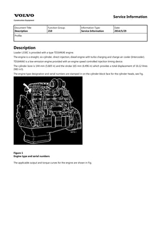
  • 1. Service Information Document Title: Function Group: Information Type: Date: Description 210 Service Information 2014/5/29 Profile: Description Loader L330C is provided with a type TD164KAE engine. The engine is a straight, six-cylinder, direct-injection, diesel engine with turbo charging and charge-air cooler (Intercooler). TD164KAE is a low-emission engine provided with an engine speed controlled injection timing device. The cylinder bore is 144 mm (5.669 in) and the stroke 165 mm (6.496 in) which provides a total displacement of 16.12 litres (983 in3). The engine type designation and serial numbers are stamped in on the cylinder block face for the cylinder heads, see Fig. Figure 1 Engine type and serial numbers The applicable output and torque curves for the engine are shown in Fig.
  • 2. Figure 2 Output and torque curves
  • 3. Service Information Document Title: Function Group: Information Type: Date: Engine, checking function 210 Service Information 2014/5/29 Profile: Engine, checking function Testing for possible causes 1 First check:      Fluid levels Control and warning lamps Instruments Battery voltage Fuses (correct rating) 2 Separate systems:  If two or more systems, and/or circuits work together. CHECK THE SYSTEMS/CIRCUITS INDIVIDUALLY. 3 If the machine has poor pulling power, the fault may be in the engine, torque converter or transmission; Then check the stall speed, see Specifications.   If the engine stall speed is within the prescribed values, the fault can be found in the transmission or torque converter. If the engine stall speed is low, check according to point 4. 4 Checking engine               Checking oil and coolant respectively, discolouration, smell, etc. Checking exhaust pipe (inside sticky) Checking air filter and turbocharger. If the engine runs unevenly (imbalance–noise) Checking excess pressure in header tank. Crankcase ventilation (excess pressure/clogged) Oil dipstick, remove (excess pressure) Exhaust smoke (discolouration, smell). Bleed the fuel system. Check engine speed. Check feed pressure (before and after filter). Carry out compression test (if incorrect repeat using oil). Check the injectors. Check injection angle (injection timing).
  • 4. Service Information Document Title: Function Group: Information Type: Date: Engine, fitting 210 Service Information 2014/5/29 Profile: Engine, fitting Op nbr 21072 999 3590 Gear Ratchet block 750 kg (1654 lb), 4 pcs Lifting sling 2 m (6.5 ft), 4 pcs Lifting sling 4 m (13 ft) Lifting sling 3 m (10 ft) Shackle 7/16", 2 pcs Shackle 5/8", 2 pcs Shackle adapted for lifting device Pipe Ø50 mm (1.97 in), length 800 mm (31 in), thickness of material approx. 4 mm (0.16 in) 1. Check that the bushing for the bearing stud and the ring gear are positioned in the flywheel. 2. Fit a new seal to the torque converter connection flange, also apply sealing compound type black silicone on the connecting flange. 3. Position a piece of board or sheet metal against the radiator so that it will not be damaged, see Fig. [Invalid linktarget] 4. Connect a hoist to the engine and lift in the engine according to Fig. [Invalid linktarget] Incline the engine so that the bearing stud on the torque converter does not catch in the flywheel housing. 5. Connect the hose for draining the oil to the oil sump. 6. Place the engine horizontally and move it against the torque converter. Rotate the flywheel according to Fig. so that the teeth enter engagement.
  • 5. Figure 1 Rotating flywheel 1. 999 3590 CAUTION Make sure that the rubber boots at the inlet manifold of the hydraulic oil pumps are under load. 7. Fit the bolted joint flywheel housing–torque converter and clamp the cable harnesses with the upper bolts. Tightening torque 60 N m (44 lbf ft). 8. Fit the front right engine mounting. Tightening torque 220 N m (162 lbf ft). 9. Position the rubber dampers for the engine mountings together with washers and bolts. Lower the engine and at the same time gradually take the load off the ratchet blocks in which the torque converter is suspended. 10. Tighten the bolts for the rubber dampers of the engine mountings. Tightening torque 350 N m (258 lbf ft). 11. Connect the coolant pipe between coolant pump and transmission oil cooler. Use a new O-ring. NOTE! Connect the coolant pump end first. 12. The following applies to machines equipped with air conditioning: Bolt on the AC compressor and tension the drive belt. Fit the member for the lower bracket of the condenser and bolt on the condenser. CAUTION Do not bend the hoses so that they break. A broken hose must be changed. 13. Connect the following on the right side of the engine:     Cable harness and cable connections to the alternator, temperature sensor and tank sensor. Cable connections to air conditioning pressure monitor (if fitted). The hoses to the cab heater. The engine part-flow oil filter. 14. Fit the pipe between the transmission oil cooler and the thermostat housing. 15. Fit the pipe between the lower connection on the radiator and the thermostat housing.
  • 6. 16. Connect the following on the left side of the engine:        Cable harness and cable connections to starter motor. The fuel system prefilter. The fuel lines to the fuel pump. The bracket with the engine speed control. The control cable to the control arm on the injection pump. The bracket and relay for the air preheater. The bracket with the transmission oil filters. 17. Position the superstructure according to Fig. Figure 2 Fitting superstructure Lift according to Fig. Figure 3 Position of lifting points
  • 7. 1. 2. Sling 4 metres (13 ft) Shackle 7/16" At the same time connect the hose for the turbocharger. Adjust the height of the superstructure with the required number of washers under the rubber dampers. 18. Connect the following:     The hoses to the header tank. The electrical lead to the air filter indicator. The coolant hoses to the engine. The pipe to the exhaust side of the turbocharger. 19. Fill with coolant and engine oil. 20. Disconnect the frame joint lock. 21. Bleed the fuel system. Start the engine and check that there are no leaks. 22. Fit the cover above the hydraulic tank and the side plates.
  • 8. Service Information Document Title: Function Group: Information Type: Date: Engine, removing 210 Service Information 2014/5/29 Profile: Engine, removing Op nbr 21070 E 1034 Nipple Ratchet block 1500 kg (3308 lb) Ratchet block 750 kg (1654 lb), 3 pcs Sling, 2 m (6.5 ft), 4 pcs Sling, 3 m (10 ft) Sling, 4 m (13 ft) Shackle 7/16", 2 pcs Shackle 5/8", 2 pcs Shackle adapted for lifting device Nipple part no. 11 054 659 Pipe Ø50 mm (2 in), length 800 mm (31 in), thickness of material 4 mm (0.16 in) 1. Secure the frame joint with the frame joint lock. 2. Turn off the battery disconnect switch. 3. Drain the coolant, using E1034. Drain the engine oil using nipple part. no. 11054659. WARNING There is a danger of scalding when removing the cap for the header tank (radiator cap), as the cooling system is pressurised when hot. 4. Remove the side plates and the cover above the hydraulic tank and open the side covers. 5. Detach the following connections to the superstructure:      The hoses from the header tank. The electrical lead from the air filter indicator. The turbocharger inlet hose. Hoses from the engine. The pipe from the turbocharger exhaust side. 6. Remove all attaching bolts (4 pcs) for the superstructure. Note the number of washers on the rubber dampers on which the superstructure stands. The weight of the superstructure is approx. 340 kg (750 lb).
  • 9. 7. Connect a hoist according to Fig. Figure 1 Position of lifting points 1. 2. Sling 4 metres (13 ft) Schackle 7/16" 8. Lift away the superstructure according to Fig. Figure 2 Removing superstructure 9. For machines equipped with air conditioning, the following applies: – Remove the condenser attaching bolts. Position the condenser according to Fig
  • 10. Figure 3 Position of condenser CAUTION Do not loosen the hose connections to the condenser. NOTE! Do not bend the hoses, so that they break. A broken hose must be changed. Remove the member for the lower brackets of the condenser. – Remove the compressor drive belt and attaching bolts. CAUTION Do not loosen the hose connections to the compressor. Position the compressor according to Fig. Figure 4 Position of compressor
  • 11. NOTE! Do not bend the hoses so that they break. A broken hose must be changed. 10. Detach the following from the right side of the engine:    Cable harness. The hoses to the cab heater. The engine part-flow filter. 11. Remove the coolant pipe from the thermostat housing connecting pipe. 12. Remove the coolant pipe from the lower connection on the radiator. 13. Loosen the transmission oil cooler at the front end and detach the coolant pipe. Position the pipe under the transmission oil cooler. 14. Detach the following from the left side of the engine:        Cable harness and cable connections to starter motor. The fuel system prefilter. The fuel lines from the fuel pump. The bracket for the engine speed control. The control cable from the control arm on the injection pump. The bracket and relay for the air preheater. The bracket for the transmission filters from the frame. 15. Remove the engine mounting bolts at the rubber dampers. NOTE! If the machine is provided with secondary steering, it may be necessary to disconnect certain hoses in order to improve accessibility. 16. Suspend the torque converter against the hydraulic tank according to Fig. Figure 5 Suspension of torque converter 1. 2. 3. Pipe length 0.8 metre (31 in) Ratchet block 750 kg (1654 lb) Sling 2 m (6.5 ft)
  • 12. 4. Lifting eye 3/4" UNC 17. Suspend the hydraulic pumps according to Fig. Figure 6 Suspending hydraulic pumps 1. Sling 4 m
  • 13. Figure 7 Suspending hydraulic oil pumps 1. 2. Sling 2 m (6.5 ft) Ratchet block 750 kg (1654 lb) 18. Detach the hose from the flywheel housing. 19. Connect a hoist to the engine, see Fig. [Invalid linktarget] The engine weight is approx. 1430 kg (3153 lb). 20. Lift the engine so that the rubber dampers are unloaded. Tension the ratchet blocks which are connected to the torque converter. CAUTION Make sure that the rubber boots on the inlet pipes do not have to take any load. Remove the washers and the rubber dampers. Figure 8 emoving engine 1. 2. 3. 4. Sling 3 m (10 ft) Ratchet block 1.5 tonnes (3307 lb) Shackle 5/8", 2 pcs Shackle adapted for the lifting device 21. Remove the front right engine mounting. 22. Position a protective board or metal sheet against the radiator by the belt pulley. See Fig.
  • 14. Figure 9 Guard for radiator 1. Piece of board 23. Remove the bolts between the flywheel housing and torque converter housing. Press the parts apart according to Fig. Figure 10 Pressing flywheel housing and torque converter housing apart 1. Puller bolt, upper (lower botl is positioned diametrically opposite) NOTE! The figure shows the upper puller bolt. The lower puller bolt is positioned diametrically opposite the upper one.
  • 15. 24. Pull the engine rearward and lift it approx. 20 cm (8 in) CAUTION The bearing stud in the torque converter. 25. Detach the hose from the draining nipple under the engine oil sump. 26. Incline the engine according to Fig. so that the bearing stud on the torque converter will go free when the unit is lifted further. Figure 11 Position of engine to clear the torque converter bearing stud. 27. Remove the engine.
  • 16. Suggest: If the above button click is invalid. Please download this document first, and then click the above link to download the complete manual. Thank you so much for reading
  • 17. Service Information Document Title: Function Group: Information Type: Date: Description 211 Service Information 2014/5/29 Profile: Description The engine has one separate cast iron cylinder head for each cylinder with replaceable guides and valves seat inserts. There are four valves per cylinder (two inlet and two exhaust valves). Inlet and exhaust ducts open out on either side of the cylinder head. The injector is vertically positioned straight above the piston crown centre in thin replaceable copper sleeves which are directly cooled by circulating coolant. Figure 1 Cylinder head
  • 18. Service Information Document Title: Function Group: Information Type: Date: Cylinder block 212 Service Information 2014/5/29 Profile: Cylinder block The cylinder block is made of cast iron and is cast in one piece and provided with "wet" replaceable cylinder liners. The significance of "wet" cylinder liners is that they are in direct contact with the coolant. The crankshaft is journalled in the cylinder block in replaceable, pre-finished main bearing shells. The centre main bearing location is also provided with a thrust bearing. The main bearing caps are made of nodular iron. They are, in addition to the usual bolted joint, also connected to the sides of the cylinder block through reinforcing plates in order to contribute to a lower sound level. Figure 1 Cylinder block