1. UDC 621.31521 :53.758 :662.613.5 IS 10810 (Part 63) : 1993
Indian Standard
METHOD OF TESTS FOR CABLES
PART 63 MEASUREMENT OF SMOKE DENSITY OF ELECTRIC CABLES
UNDER FIRE-CONDITIONS
1 Scope
This standard gives the test method for the measurement of smoke emitted when electric cables are burnt
under defined conditions.
2 Significance
2.1 The assessment of smoke density is an important factor for evaluating the behaviour of electric cables
under fire conditions. The smoke evolved by one or more burning cables is not necessarily reflected by the
testing of the individual components and, therefore, test method is recommended for cable assemblies.
2.2 This draft describes the test apparatus and the procedure, but leaves open the question of sample
mounting. This is because further experiment is required in order to precisely define the best method for
minimium dispersion of results with different operators.
2.3 The draft includes a proposal for standardizing the performance of the test chamber and equipment by
the use of a blanktest based on-a defined volume of smoke.
3 Terminology
3.1 As given in IS 1885 ( Part 32 ) : l-971 ‘Electrotechnical vocabulary : Part 32 Cable conductors and
accessories for electricity supply’.
4 Test Apparatus
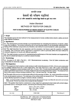
4.1 The equipment shall comprise a cubic enclosure with inside dimensions of 3 000 2 30 mm and constructed
for suitable material fixed into a steel angle frame. One side shall have a door, with a glass observation
window. Transparent sealed windows (size 100 -c 10 mm x 100 2 10 mm) shall be provided on two opposite
sides to permit the transmission of a beam of light from the horizontal photometric system. The distance from
floor to the centre of these windowsshall be 2 150 -c 100 mm (see Fig. 1 for plan view).
4.2 The walls of the enclosure shall include orifices for the passage of cables, etc, and to permit the enclosure
to be at atmospheric pressure. The total area of the orifices shall not exceed 50 cm*. The enclosure should
not be directly exposed to sunlight or extreme climatic conditions.
Note -It must be possible to extract fumes from the enclosure afler each test through a duct fitted with valve which can be closed
during the test. The duct may include a fan to increase the rate of extraction,.
4.2.1 The ignition fluid shall be contained in a tray made from galvanized sheet metal with jointed edges,
pyramidal trunk or rectangular section, and having the following interior dimensions:
Bottom 210x~10x110~10mm
Top 240~10x140~10mm
Height 80+10mm
July 1993 0 BIS 1993
BUREAU OF INDlAti STANDARDS
MANAK BHAVAN, 9 BAHADUR SHAH ZAFAR MARG
NEW DELHI 110002
Price Group 4
( Reaffirmed 1998 )
2. IS 10810 (Part 83) : 1993
ILIGHT SOURCE
Ic
1500mm
I
I
DRAUGHT S&EN
HEIGHT 1OOOmm
I
l-H
.---’
OPTICAL PATH HEIGHT 2150mm
--___-
-t
___---
‘u FANFLOW 10 :” 15m3,(mjn
PHOTOCELL
f DOOR
ki. 1 PLAN VIEW OF TEST CHAMBER
4.2.2 The weight of the tray shall be approximately 250 g.
4.2.3 The tray shall be supported on a metal trestle.
4.3 Smoke Mixing
In order to ensure uniform distribution of the smoke, a table type fan shall be placed on the floor of the cube
as shown in Fig. 1. The fan shall have a blade sweep of 300 mm 2 20 percent and a flow rate of 10 to 15
M3/min. Air shall be blown horizontally by the fan.
4.4 Photometric System
4.4.1 The photometric system is illustrated in Fig. 2. The light source and the receiver shall Abe placed
externally in the centre of two opposite walls of the cube without making physical contact with these walls.
The light beam shall traverse the cube through the glass windows in the side walls.
4.4.2 The light source shall be a halogen lamp with a tungsten filament with a clear quartz bulb, havin? the
following characteristics:
Power 1oow
Stabilized voltage 12 rt 0.01 v
Nominal luminous flux 2 000 - 2 500 lumens
Nominal colour temperature 2800-3200k
2
3. IS 10810 (Part 63) : 1993
r-- QUARTZ/HALOGEN BULB
i
LENS SYSTEM
------
r , 5ommPHOT”r;“i
4)
-r--
LIGHT BEAM -
STABILIZED VOLTAGE
SUPPLY 12.00 f 0.01 v
3000mm
WINDOWS OF THE CUBE
~Notes
1 The light source and the photocell must be physically isolated trom the flv,k of the cube.
2 The diameter of the cone of light on the opposite face from the source of approximately 1.5 m.
FINISHED INSIDE
WINDOW FOR DUST
PROTECTI’JN
FIG. 2 PHOTOMETRIC SYSTEM
4.4.2.1 The lamp shall be mounted in a housing and the beam adjusted by lens system to give an evenly
illuminated circular areas of diameter 1.5 * 0.1 m on the interior of the opposite wall.
4.4.3 The receptor photocell shall be mounted at one end of a 150 f 10 m tube with a dust protection window
at the other end. The inside of the tube shall be matt black to prevent reflections. The photocell shall be
connected to a potentiometric recorder to produce a linear proportional output. The cell shall be resistance
loaded to operate in its linear range and the input impedance of the recorder should be at least 10 times
greater than load resistance of the cell.
5 Material
5.1 Ignition Fluid
The ignition fluid shall be 1 + 0.01 litres of distilled alcohol, having the following composition:
Ethanol 90 * 1 percent
Methanol 4 2 1 percent
Water 6 + 1 percent
~6 Test Specimen
6.1 The size and number of test pieces and their assembly is given in 6.2 to 6.4.
Note - The method of handling some samples of large diameter cables has been shown to influence the results significally. For
example, identical cable selected from drums having differing barrel dimensions may produce different values of absorbance. Where
more than one test piece is involved, it is essential to define their disposition and whether they are bound tightly or unbound or
precisely spaced. Where cables are small, that is 10 mm in diameter, their disposition in the test assembly must be defined because
a substantial number are normally involved offering many possible arrangements.
6.2 Lengths of cable, measuring 1 000 ‘c 50 mm shall be carefully straightened.
3
4. IS10810(Part63):1993
6.3 Number of TestSpecimen
10 mm dia Under consideration
10mmto 25mmdia 3
25 mm to 40 mm dia 2
40 mm dia 1
BACK WALL
6.4 Assembly of Test Piece
FIG. 3 METHOD OF SUPPORT OF TEST PIECE
6.4.1 The assembly shall be tested as a flat horizontal unit placed symmetrically above the tray by means
of vertical supports equipped with horizontal brackets (Fig. 3) such that the vertical distance of the bottom of
the test assembly from the bottom of the tray is215 + 5 mm.
6.4.2 The bundles or the individual test pieces shall be held together in close contact throughout the length.
The binders shall be metallic and placed at the ends of 300 + 20 mm from each end of the test piece.
7 Conditioning
7.1 The cable sample shall be conditioned for at least 24 hours at 27 + 2%.
4
5. IS 10810 (Part 63) : 1993
8 Procedure
8.1 Calibration of the Test Equipment
8.1 .l In order to ensure that results with different apparatus are comparable, it is essential to eliminate any
dispersion in results caused by deviation in the test apparatus. A standardization procedure as given in
Annex A uses a defined density of smoke. .
8.1.2 The photometric system is energized before the blank test (see 8.3). When stability has been attained,
the zero and full scale reading of the recorder shall be adjusted to correspond respectively to 0 and 100
percent transmission of the light. The full reading of the recorder corresponding 100 precent transmission of
the light represents I,, the initial transmittance.
Note-Periodically, it is necessary to verify the performance of the photocell by placing in the light beam standard neutral density
filters which must cover the entire optical entry part of the photocell. The values of absorbance (or opticai density) measured by
the photocell must fall within ~5 percent of the standard values. The filters shall also permit the verification of linearity of response
of the detector which must be proportional to the absorbance of light in the range used.
82ln order to avoid the effect of humidity deforming the absorbance level a blank test is carried out prior to
any single test of series of tests carried out in rapid succession.
8.3 fgnite 1 5 0.01 litre of alcohol (see5.1) in the tray with no cables’ place. The door of the cube is left partly
open to allow air to enter the enclosure. The cube shall then be purged of all combustion products by operating
the extraction system.
8.4 The interior temperature of the test cube shall measure 30 f 5% prior to the beginning of each test.
8.5 The following series of operation are carried out :
a) Close the valve in the extraction system;
b) Place test piece on its support;
c) Measure alcohol and pour into tray (see Fig. 1);
d) Start the air circulation fan;
e) Ignite the alcohol, start chronometer and chart recorder; and
f) Close door.
8.6 a) The test is finished when there is no change in light transmittance for 5 minutes after the source
has extinguished;
b) Remove test piece for observation;
c) Purge the cube of combustion products prior to the next test; and
d) If no blank test is to be performed, it may be necessary to clean the windows of the photometric
system to regain 100 percent transmission after stabilization of the voltage.
9 Tabulation of Observation
External Dia
of Cable
Number of Initial Light
Cables Transmittance
n I,
Final Light
Transmittance
I,
10 Calculation
-10.1 The standard absorbance (AJ is calculated as under :
Measured absorbance (A,) = log ,0 $
t
5
6. IS 10810 (Part 63) : 1993
Standard absorbance across I metre cube :
A, =
A, x cube factor
n
where cube factor =
Volume of cube(m”)
Length of light path(m)
n = Number of individual cables.
11 Report
11.l The result obtained are reported as under:
Designation of Material Measured Absorbance Standard Absorbance
--
.-
11.2 The following criteria should be used in judging acceptability of smoke density rating data:
11.2.1 Repeatability
Two individual resujts (not average) determined by a single operator in one laboratory should not be
considered suspect (at 95 percent confidence level) unless they differ by more than 18 percent absolute.
11.2.2 Repruducibility
Two results from different laboratories (based on the average of threetests) should not be considered suspect
(at 95 percent confidence level) unless they differby more than 15 percent absolute.
ANNEX A
(Ckwe 8.1)
CALIBRATION ON TEST APPARATUS
A-l Preparation of Test Solution
A-l_.1 Solutions of one litre of toluene mixed with the alcohol used forthe test shall be made up in the following
respective volumes 4 : 96 and 10 : 90, using a pipette and a volumetric flask for accuracy of measurement.
A-l .2 Test Procedure
Follow the procedure for the blank test (8.3) noting the transmittance level (/J at the end of the test.
A-l .3 Verification Procedure
Calculate the measured absorbance (A,) as follows:
A,,,=
‘cl
‘og 10J-
t
where
I, = Initial transmittance.
Calculate the standard absorbance (A,J
7. IS10810(Part63) :1993
A,, =
A, Volume of cube(m3)
Percent toluence ’ Optional path length (m)
Recommended values of A, are :
4 percent Toluene
10 percent Toluene
0.18 to 0.26
0.80 to 1.20
EXPLANATORY NOTE
The standard has been prepared by referring to IEC Dot : 20 (Secretariat) 212.
Printed at New India Printing Press, Khurja, India
7