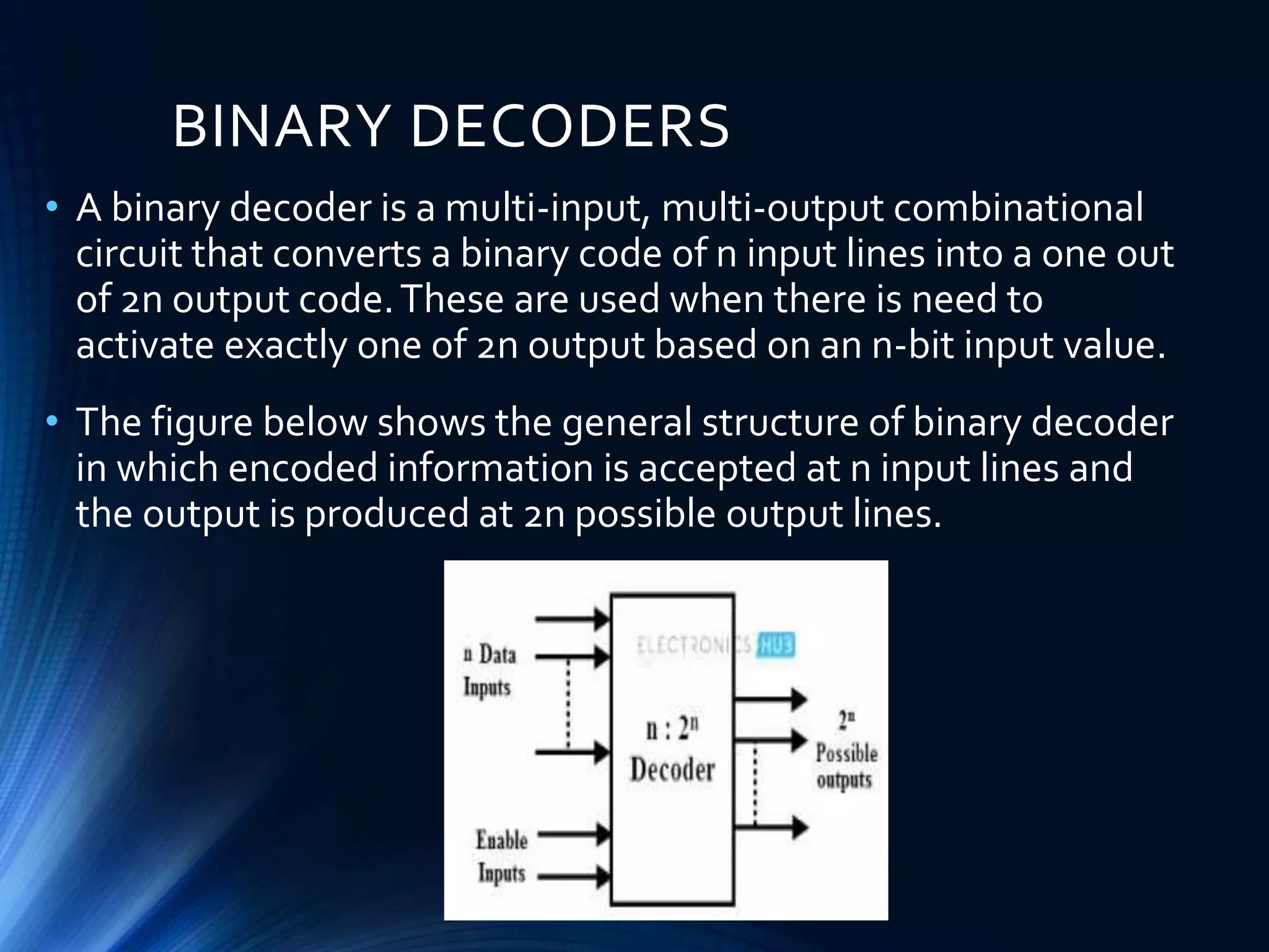
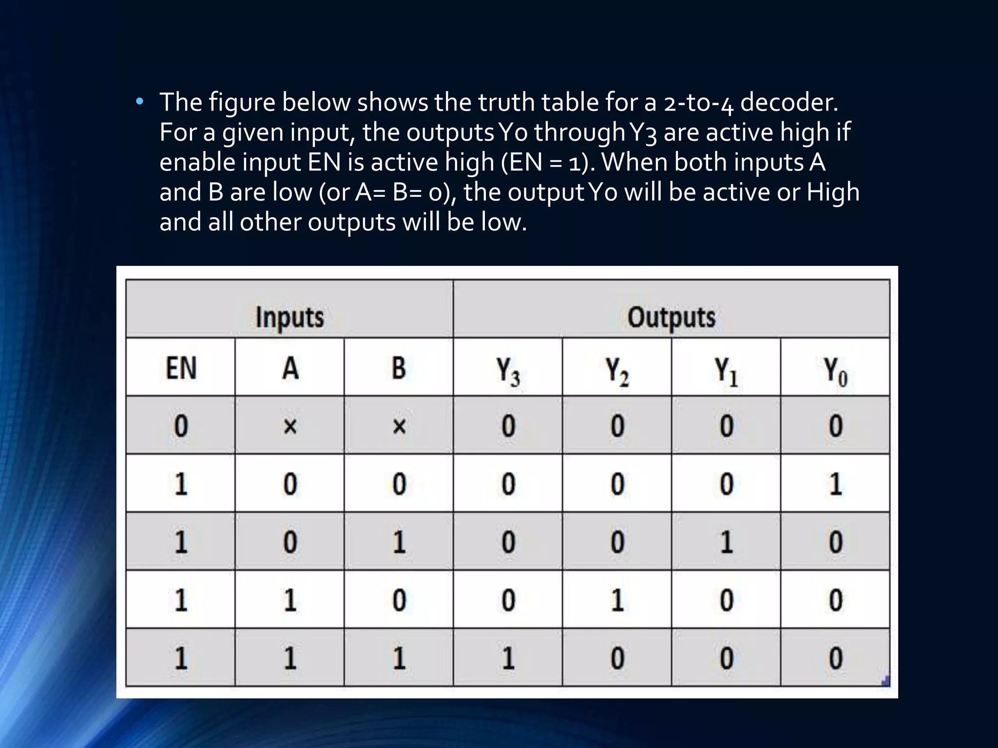
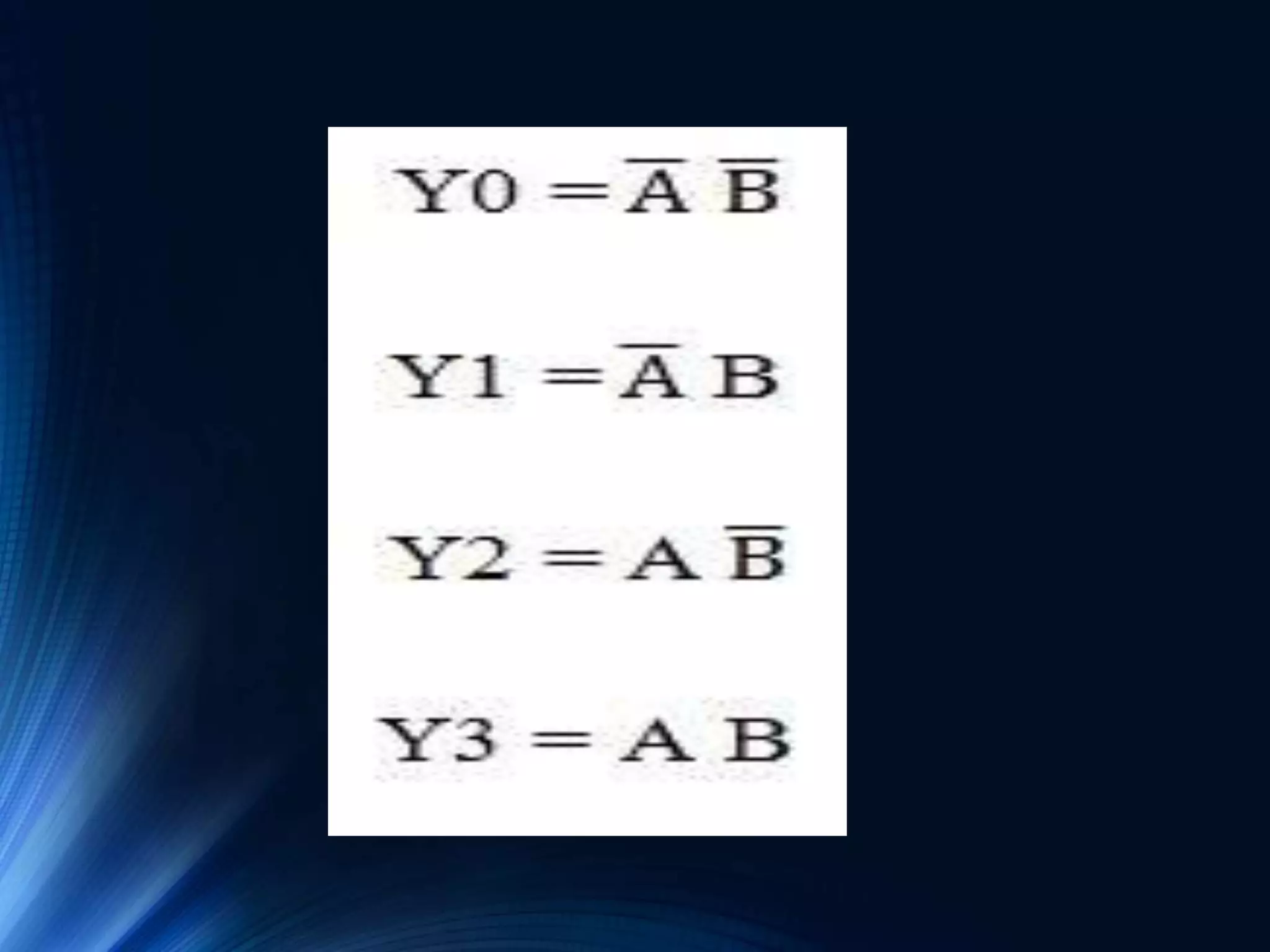
2. BINARY DECODERS
• A binary decoder is a multi-input, multi-output combinational
circuit that converts a binary code of n input lines into a one out
of 2n output code.These are used when there is need to
activate exactly one of 2n output based on an n-bit input value.
• The figure below shows the general structure of binary decoder
in which encoded information is accepted at n input lines and
the output is produced at 2n possible output lines.
4. • The figure below shows the truth table for a 2-to-4 decoder.
For a given input, the outputsY0 throughY3 are active high if
enable input EN is active high (EN = 1).When both inputs A
and B are low (or A= B= 0), the outputY0 will be active or High
and all other outputs will be low.
5. • From the above truth table we can obtain Boolean expression
for the each output as
• These expressions can be implemented by using basic logic
gates.Thus, the logic circuit design of the 2-to-4 line decoder is
given below which is implemented by using NOT and AND
gates.Two NOT gates or inverters provide the complement of
inputs.
• A common enable line is connected to eachAND gate such that
when EN= 0 all the outputs are zero and if EN=1, depends on the
inputs A and B, outputs are produced. Each output represents
one of the minterms of the 2 input variables.
6.
7.
8. • It is also possible to design 2-to-4 decoder using NAND gates as
shown in figure below along with truth table.This is constructed
with a principle of max terms as outputs.To generate the
minterms, we have to use NAND gates which act as inverters. If
both inputs are zero (A = B = 0),Y0 will be zero , if A = 0 and B= 1,
thenY1 will be 1 and so on.
• Therefore, only one output will be low for any combinations of
inputs at a given time and all other outputs will be high.This type
of decoders is available in IC forms so that 3 to 8, 4 to 16, and 5 to
32 decoders can also be made depends on the application
requirement.