ER to relational Mapping: Data base design using ER to relational language. Ch7 (Navathe 4th edition)/ Ch9 (Navathe 3rd edition)
•Download as DOCX, PDF•
0 likes•672 views

ER to relational Mapping: Data base design using ER to relational language. Ch7 (Navathe 4th edition)/ Ch9 (Navathe 3rd edition)

Recommended
Recommended
More Related Content
What's hot
What's hot (20)
Similar to ER to relational Mapping: Data base design using ER to relational language. Ch7 (Navathe 4th edition)/ Ch9 (Navathe 3rd edition)
Similar to ER to relational Mapping: Data base design using ER to relational language. Ch7 (Navathe 4th edition)/ Ch9 (Navathe 3rd edition) (20)
More from Raj vardhan
More from Raj vardhan (20)
Recently uploaded
Recently uploaded (20)
ER to relational Mapping: Data base design using ER to relational language. Ch7 (Navathe 4th edition)/ Ch9 (Navathe 3rd edition)
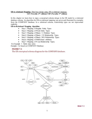
- 1. 1 ER to relational Mapping: Data base design using ER to relational language. Ch7 (Navathe 4th edition)/ Ch9 (Navathe 3rd edition) In this chapter we learn how to map a conceptual schema deisgn in the ER model to a relational database schema. An algorithm for ER-to-relational mapping was given and illustrated by examples from the COMPANY database. In a relational schema, relationship types are not represented explicitly. ER-to-Relational Mapping Algorithm Step 1: Mapping of Regular Entity Types Step 2: Mapping of Weak Entity Types Step 3: Mapping of Binary 1:1 Relation Types Step 4: Mapping of Binary 1:N Relationship Types. Step 5: Mapping of Binary M:N Relationship Types. Step 6: Mapping of Multivalued attributes. Step 7: Mapping of N-ary Relationship Types. For Example 1 : Refer class notes Example 2 is based on COMPANY Database:
- 2. 2 Step 1: Mapping of Regular Entity Types. For each regular (strong) entity type E in the ER schema, create a relation R that includes all the simple attributes of E. Choose one of the key attributes of E as the primary key for R. If the chosen key of E is composite, the set of simple attributes that form it will together form the primary key of R. Example: We create the relations EMPLOYEE, DEPARTMENT, and PROJECT in the relational schema corresponding to the regular entities in the ER diagram. Ssn, Dnumber, and Pnumber are the primary keys for the relations EMPLOYEE, DEPARTMENT, and PROJECT as shown. Step 2: Mapping of Weak Entity Types For each weak entity type W in the ER schema with owner entity type E, create a relation R & include all simple attributes (or simple components of composite attributes) of W as attributes of R. Also, include as foreign key attributes of R the primary key attribute(s) of the relation(s) that correspond to the owner entity type(s). The primary key of R is the combination of the primary key(s) of the owner(s) and the partial key of the weak entity type W, if any. Example: Create the relation DEPENDENT in this step to correspond to the weak entity type DEPENDENT. Include the primary key SSN of the EMPLOYEE relation as a foreign key attribute of DEPENDENT (renamed to ESSN). The primary key of the DEPENDENT relation is the combination {ESSN, DEPENDENT_NAME} because DEPENDENT_NAME is the partial key of DEPENDENT. Step 3: Mapping of Binary 1:1 Relationship Types For each 1:1 relationship type R, identify the relations S and T that participating in R.
- 3. 3 Foreign key approach Choose one relation S. Include the primary key of T as a foreign key in S. It is better to choose an entity type with total participation in R in the role of S. Example: No relation is created for the 1:1 relationship type MANAGES. Include the primary key Ssn of the EMPLOYEE relation as a foreign key attribute of DEPARTMENT (renamed to Mgr_ssn). Include the attribute Start_date of the MANAGES relationship in DEPARTMENT and rename it Mgr_start_date. Step 4: Mapping of Binary 1:N Relationship Types For each binary 1:N relationship type R, identify the relation S that represents the participating entity type at the N-side of the relationship. Let T denotes the other participating entity. Include the primary key of T as a foreign key in S. Include any simple attributes of the relationship as attributes of S. Example: Map the 1:N relationship types WORKS_FOR, CONTROLS, SUPERVISION. WORKS_FOR: Include the primary key Dnumber of DEPARTMENT as foreign key in EMPLOYEE. Call it Dno. SUPERVISION: Include the primary key of EMPOYEE as foreign key in EMPLOYEE. Call it Super_ssn. CONTROLS: Include the primary key Dnumber of DEPARTMENT in PROJECT. Call it Dnum. Step 5: Mapping of Binary M:N Relationship Types For each binary M:N relationship type R, create a new relation S. Include the primary keys of both participating entities as foreign keys. Their combination will form the primary key of S. Also include any simple attributes of R. Example: Create the relation WORKS_ON. Include the primary keys of PROJECT and EMPLOYEE as foreign keys. Rename them Pno and Essn. Also include an attribute Hours. The primary key is the combination of {Essn, Pno}. Step 6: Mapping of Multivalued attributes. For each multivalued attribute A, create a new relation R. This relation R will include an attribute corresponding to A, plus the primary key attribute K (as a foreign key in R) of the relation that represents the entity type of relationship type that has A as an attribute. The primary key of R is the combination of A and K. If the multivalued attribute is composite, we include its simple components. Example: The relation DEPT_LOCATIONS is created. The attribute DLOCATION represents the multivalued attribute Locations of DEPARTMENT, while Dnumber (as foreign key) representing the primary key of the DEPARTMENT relation.The primary key of R is the combination of {Dnumber, Dlocation}.
- 4. 4 Step 7: Mapping of N-ary Relationship Types. For each n-ary relationship type R, where n>2, create a new relation S to represent R. Include as foreign key attributes in S the primary keys of the relations that represent the participating entity types. Also include any simple attributes of the n-ary relationship type (or simple components of composite attributes) as attributes of S. Example: The relationship type SUPPY in the ER-diagram on the next slide. This can be mapped to the relation SUPPLY shown in the relational schema, whose primary key is the combination of the three foreign keys {Sname, Part_no, Proj_name}