MANUFACTURING PROCESS-II UNIT-1 THEORY OF METAL CUTTING
Lecture 18
1. Module 6 : Robot manipulators kinematics
Lecture 18 : Homogeneous coordinate transformation and examples
Objectives
In this course you will learn the following
What is meant by homogeneous coordinate systems for manipulators.
Its properties & Example for the same.
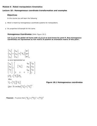
Homogenous Coordinates (Refer Figure 18.1)
Let x1,y1,z1 be global ref frame with x2,y2,z2 as local frame for point P. Now homogenous
coordinates are represented as 4x4 matrix of position & orientation matrix of this point .
Figure 18.1 Homogeneous coordinates
Theorem : To prove that
2. Fig. 18.2 Ref & body attached coordinate systems
Here we would like to find 3x3 transformation matrix R that will transform the coordinates of puvw to the
coordinates expressed w.r.t. the OXYZ coordinate system, after the OUVW coordinate system has been
rotated. That is
Recalling the definitions of the components of a vector, we have
where represent the projections of p onto respective axis. Now using definitions of scalar
product and above equation, we have
OR expressed in matrix form, it will be as
Similarly one can obtain the coordinates of puvw from coordinates of pxyz as,
from above two equations; since dot product are commutative we can write
Thus we have proved the theorem.
Theorem : To prove that
3. Fig. 18.2 Ref & body attached coordinate systems
Here we would like to find 3x3 transformation matrix R that will transform the coordinates of puvw to the
coordinates expressed w.r.t. the OXYZ coordinate system, after the OUVW coordinate system has been
rotated. That is
Recalling the definitions of the components of a vector, we have
where represent the projections of p onto respective axis. Now using definitions of scalar
product and above equation, we have
OR expressed in matrix form, it will be as
Similarly one can obtain the coordinates of puvw from coordinates of pxyz as,
from above two equations; since dot product are commutative we can write
Thus we have proved the theorem.
Example
Find position and orientation matrices (transformation) of end effecter in initial and final position for the
system shown below.
Solution :
A object with 3 pegs is placed on a table as shown below Figure 18.3. It need to be picked up & placed on
another inclined plane part as shown. Problem is about matching the two coordinate systems viz
(x2,y2,z2) to (x5,y5,z5).
4. Figure 18.3
Data given that,
The rotation matrix is ( All 3x3 matrices) & Transformation
matrix is (4x4) which need to be found for initial & final position of
part.
Part (A)
We have ,
Also, local coordinate systems 4, 5 & 6 are parallel. Therefore their rotation
matrices are Identity matrices.
Thus rotation matrix in global coordinate is known for final position of End effecter (EE).
Also for initial position of part, the coordinate systems are parallel to each other except directions.
Therefore rotation matrix is
5. Part(B)
To find the transformation matrices for initial & final position of end
Effecter, we proceed as follows.
For initial position of EE,
For final position of EE,
Thus all the matrices are known from above to calculate
Recap
In this course you will learn the following
Specifying position and orientation of rigid bodies can be done by homogeneous coordinate representation
How to express end effector coordinate in base reference frame using homogeneous coordinates
Congratulations, you have finished Lecture 18. To view the next lecture select it from the left hand side
menu of the page