SlideShare a Scribd company logo
1 of 75
Download to read offline
Introduction
The field of science, which deals with energies possessed and exchanged by a system of gases
and vapours, their conversion in terms of heat and work and their relationship with properties
of system is called thermodynamics. Thus in thermodynamics, we deal with conversion of
energy from one form to the other, mainly heat into work or vice versa. In this context, we must
know the overall scenario of conversion of available forms of energy into usable forms as
shown below:
Figure: Energy conversion chart
Application of Thermodynamics
 Power Generation (Thermal/Nuclear Power plants)
 Automobiles (Petrol/ Diesel/LPG/CNG engines)
 Processing Industries (Steam generation, Refrigeration systems)
 Gas Compressors (Air compressors)
Thermodynamics Definition:
Is the science of energy transfer and its effect on the physical properties of substance.
Thermodynamics is primarily concerned with two forms of energy i.e. "Heat & Work". It is
basically based on four laws of thermodynamics known as zeroth, first, second and third law.
Thermodynamic principles are used in the designing of energy converting devices, such as,
steam engines, IC. engines, steam and gas turbines, refrigerators, air conditioners, fuel cells
etc.
Thermodynamic System:
It is defined as a definite region or space (area) or a quantity of matter on which attention is
focus for the study of work and heat transfer and conversion.
Figure: A Thermodynamic System
Boundary:
It is defined as actual or hypothetical envelope enclosing the system. The boundary may be
real or imaginary. It may be fixed or movable in nature.
Surrounding :
It is defined as the space and matter extremal to the thermodynamic
system and outside boundary.
Universe:
System + Boundary + Surrounding
Types of System:
1. Open System:
A system is called an open system if the mass as well as the energy
transfers and its boundaries. Examples 1. IC engines 2 Turbines 3. Nozzles etc.
2. Closed System:
In this type of system no matter or mass may enter or leave across the system boundary,
there may be energy (heat or work) transfer across the system boundary
Examples 1.A certain quantity of fluid in a cylinder bounded by a piston constitutes
a closed system. 2. Thermal power plants
Figure 2: Types of Systems
3. Isolated System:
Neither mass nor energy transfers can take place through its boundaries. Example Fluid
enclosed Insulated in a perfectly insulated closed vessel (Thermos -Flask).
Figure 2.1: Types of Systems
4.Adiabatic System:
the system which is thermally insulated from its surrounding is called adiabatic system it can
power exchange work with the surrounding if it does not, it become an isolated system.
Other classification of system:
Homogeneous system:
system or quantity of mass which consists of a single phase is called homogeneous system.
Example mixture of air and water vapor, solution of NH3 in water.
Heterogeneous System:
A system which consists of two or more phase, called heterogeneous system. Example 1
water and steam 2. ice and water 3 water and oil etc.
Phase:
A phase is a quantity of matter which is h homogeneous throughout in chemical composition
and physical structure.
Thermodynamic equilibrium:
A system is said to be in a state of thermodynamic equilibrium if the values of the microscopic
properties (such as temperature pressure etc.) at all the point are same. thermodynamic
equilibrium is a complete equilibrium and it is including the following equilibrium:
1. Mechanical equilibrium
there are no unbalanced forces within the system or between the surrounding and system is
known as mechanical equilibrium. In this case magnitude of of resultant force is zero.
2.Chemical equilibrium
in this equilibrium NO2 chemical reaction take place in the system and the chemical
composition which is same throughout the system does not vary with time.
3. Thermal equilibrium
the temperature of the system does not change with time and has the same value at the all
point in the system its mean temperature gradient is not available or can be considered as
zero in thermal equilibrium.
4. Electrical equilibrium
If there exist and uniformity of electrical potential throughout the system it can be treated as
in electrical equilibrium.
Property of substance
Any characteristics of a substance which can be observed on major is called property of
substance. Example pressure temperature mass specific volume etc.
(a) intensive property:
these properties do not depend on the mass of the system. Intensive properties are generally
denoted by lowercase letter with major exceptions pressure” P” and temperature “T”, which
are always intensive.
Example temperature (T), pressure (P), specific volume (v), density (ρ) etc.
(b) extensive property:
these properties depend on the mass of the system. If mass changes, there value also changes.
These are generally denoted by upper case letter with major exceptions like mass “m”,
number of moles “n”.
Examples volume (V), energy (E), total enthalpy (H), entropy (S), potential energy (PE),
kinetic energy (KE) etc.
The ratio of two extensive property of a homogeneous system is an intensive property. Like
ratio of mass and volume is density which is intensive property. when an extensive property
is divided by the mass or number of moles of a substance forming the system, the resulting
intensive property is called a specific property. Example: specific volume, specific energy
etc.
State, Change of State, Path, Process, Cycle
State: State is the condition of the system at an instant of time as described on measured by
it properties for each unique condition of a system.
Change of State:
Any operation in which one or more of the properties of a system changes is called a change
of state.
Path:
thermodynamic system passing through a series of state constitutes a path.
Process:
when a system changes its state from one equilibrium state to another equilibrium state, then
the path of successive States through which the system has passes is known as
thermodynamic process.
Cyclic process:
cyclic process consists of number of processes incorporated to achieve the target in
thermodynamics cycle the initial and final state of process are same.
Reversible and Irreversible Process
In reversible process, the initial state and final states are same, together with all energy
transfer or transfer during the process can be completely restored in both system and
surroundings. No heat loss, friction loss and traces of path cannot be observing after
reversing the process. In reality no thermodynamic process is completely reversible. Same
path and traces can be followed to achieve reversibility.
The reversal process having following condition which must be satisfied:
1. The process processed at an extremely slow rate so that it goes inside with the Quasi
static process.
2. The system should be free from dissipative forces like friction, inelasticity, viscosity,
electrical resistance etc. This is because energy spent against such forces cannot be
recovered.
3. No heat, work and friction losses should occur during process.
4. A Reversible process should not leave any traces to show that the process had ever
occurred.
5. It should not leave any history behind its mean no change should be created on
environment.
Figure: (a) Reversible Process (b) Irreversible Process
In Irreversible process,
If the energy transfer is not restored in both system and surroundings then process is called
irreversible. Heat transfer friction losses and traces of path can be observed in irreversible
process. All real or natural process are irreversible in nature. In irreversible process same
path cannot be followed if try to achieve reversibility.
Quasistatic process
In thermodynamics, a quasi-static process is a thermodynamic process that happens slowly
enough for the system to remain in internal equilibrium. An example of this is quasi-static
compression, where the volume of a system changes at a slow rate enough to allow the
pressure to remain uniform and constant throughout the system.
Quasi means ‘as if/ almost constant’, This process is a succession of equilibrium states and
infinite slowness is its characteristic feature. The definition given above is closer to the
intuitive understanding of the word “quasi-” (as if) “static” and remains technically different
from reversible processes.
Only in Quasistatic process can we define intensive quantities (like Pressure, Temperature,
Specific volume, Specific entropy) of the system at every instant during the whole process;
Otherwise, since no internal equilibrium is established, different parts of the system would
have different values of these quantities.
Any reversible process is a quasi-static one. However, quasi-static processes involving
entropy production are not reversible.
Path Function and Point Function
Path function
A Path function is a function whose value depends on the path followed by the thermodynamic
process irrespective of the initial and final states of the process. Their magnitudes depend on
the path followed during a process as well as the end states. Work (W), heat (Q) are path
functions.
An example of path function is work done in a thermodynamic process. Work done in a
thermodynamic process is dependent on the path followed by the process. A path function is
an inexact or imperfect differential.
In the P-V diagram given above we can easily see that for the same initial and final states of
the system, work done in all the three process is different.
For process A work done is b2A1a
For process B work done is b2B1a
For process C work done is b2C1a
Another example of path function is heat.
Point function
A Point function (also known as state function) is a function whose value depends on the final
and initial states of the thermodynamic process, irrespective of the path followed by the
process.
Example of point functions are density, enthalpy, internal energy, etc.
A point function is a or we can say all the properties of the system are point functions.
Point functions are exact or perfect differential.
Note: Since a point function is only dependent on the initial or final state of the system, hence
in a cyclic process value of a thermodynamic function is zero, or change in thermodynamic
property is zero.
Difference between point function and path function
Sr. no. Point Function Path Function
1
Its values are based on the state of
the system (i.e. pressure, volume,
temperature etc.)
Its values are based on how that
particular thermodynamic state is
achieved.
2
No matter by which process the state
is obtained, its values will always
remain the same.
Different processes to obtain a
particular state will give us different
values.
3
Only initial and final states of the
process are sufficient
We need to know exact path
followed by the process
4
Its values are independent of the path
followed
Its values are dependent on the path
followed
5 It is an exact or perfect differential
It is an inexact or imperfect
differential.
6 Its cyclic integral is always zero
Its cyclic integral may or may not
be zero
7 It is property of the system It is not the property of the system
8
Its examples are density, enthalpy,
internal energy, entropy etc. Its examples are Heat, work etc.
Pressure
Pressure is the force applied perpendicular to the surface of an object per unit area over
which that force is distributed. Gauge pressure is the pressure relative to the ambient
pressure.
Mathematically:
P=F/A
where: P is the pressure,
F is the magnitude of the normal force,
A is the area of the surface on contact.
Pressure is a scalar quantity. It relates the vector area element (a vector normal to the
surface) with the normal force acting on it. The pressure is the scalar proportionality
constant that relates the two normal vectors:
Atmospheric Pressure, Gauge Pressure, Vacuum Pressure
and Absolute Pressure
Absolute Pressure - The actual pressure at a given position is called the absolute pressure, and
it is measured relative to absolute vacuum (i.e., absolute zero pressure).
Gage Pressure –
Gage pressure is the pressure relative to the atmospheric pressure. In other words, how much
above or below is the pressure with respect to the atmospheric pressure.
Vacuum Pressure –
Pressures below atmospheric pressure is called vacuum pressures and are measured by vacuum
gages that indicate the difference between the atmospheric pressure and the absolute pressure.
Atmospheric Pressure –
The atmospheric pressure is the pressure that an area experiences due to the force exerted by
the atmosphere.
Equations
Pgage = Pabs − Patm Gage Pressure
Pvac = Patm − Pabs Vacuum Pressure
Pabs = Patm + Pgage Absolute Pressure
Laws of Thermodynamics
The science of thermodynamics is based on the fourth law of thermodynamics namely:
1. Zeroth law of thermodynamics
2. First law of thermodynamics
3. Second law of thermodynamics
4. Third law of thermodynamics
These all laws are deducted from experimental observations and are based on logical
reasoning. There are no mathematical proof for these laws.
Equality of Temperature
Any two bodies are said to have 'equality of temperature' when no change in any observable
property occurs when they are brought in for thermal communication. The equality of temperature is
also termed 'thermal equilibrium'.
Zeroth law of thermodynamics:
It state that, “if two system are each in thermal equilibrium with third system, then they are
also in thermal equilibrium with each other,"
First law of thermodynamics:
First law of thermodynamics is based on law of conservation of energy, which state that
"energy can neither be created nor destroyed but it can only be transferred from one form to
another form of energy".
Statement of the first law of thermodynamics for the closed system
undergoing a cycle.
" when a system undergoes a thermodynamic close and reversible cyclic process then the
net heat supplied to the system from the surrounding is equal to net work done be the system
on its surrounding".
Its mean "for a closed, and reversible cyclic process integration of energy will always be
equal to the integration of work.
A closed system can exchange energy with its surroundings through heat and work transfer.
In other words, work and heat are the forms that energy can be transferred across the system
boundary.
Both heat transfer and work transfer may cause the same effect on a system. They both are
different forms of energy in transit. Energy that enters a system as heat may leave as work or
vice versa.
(∑W) cycle = J(∑Q) cycle
or, ∮ δW = ∮ δQ
Where, J is called Joule’s equivalent. When heat and work both are measured in same unit,
value of J will be 1.
∮ δW = ∮ δQ
Sign convention The work done by a system on the surroundings is treated as a positive
quantity.
Similarly, energy transfer as heat to the system from the surroundings is assigned a positive
sign. With the sign convention one can write,
∫dQ = ∫dW
Corollary
A device or machine is impossible, which can produce work continuously without absorbing
energy from its surroundings.
Consequences of the first law:
Suppose a system is taken from state 1 to state 2 by the path 1-a-2 and is restored to the initial
state by the path 2-b-1, then the system has undergone a cyclic process 1-a-2-b-1. If the system
is restored to the initial state by path 2-c-1, then the system has undergone the cyclic change 1-
a-2-c-1. Let us apply the first law of thermodynamics to the cyclic processes 1-a-2-b-1 and 1-
a-2-c-1 to obtain
∫1-a-2dQ+ ∫2-b-1dQ - ∫1-a-2dW - ∫2-b-1dW =0
∫1-a-2dQ+ ∫2-c-1dQ - ∫1-a-2dW - ∫2-c-1dW=0
Subtracting, we get
∫2b1dQ- ∫2c1dQ – (∫2b1dW - ∫2c1dW) =0
We know that the work is a path function and hence the term in the bracket is non-zero. Hence
we find
∫2b1dQ = ∫2c1dQ
That is heat is also a path function.
Energy is a property of the system:
By rearranging we can have
∫2b1 (dQ - dW) = ∫2c1 (dQ - dW)
It shows that the integral is the same for the paths 2-b-1 and 2-c-1, connecting the states 2 and
1. That is, the quantity ∫ (dQ - dW) does not depend on the path followed by a system, but
depends only on the initial and the final states of the system. That is ∫ (dQ - dW) is an exact
differential of a property. This property is called energy (E). It is given by
dE = dQ-dW
E = KE + PE +U
where U is the internal energy. Therefore,
dE = d(KE) + d(PE) + dU = dQ-dW
Quit often in many situations the KE or PE changes are negligible.
dU = dQ – dW
An isolated system does not exchange energy with the surroundings in the form of work as
well as heat. Hence dQ = 0 and dW = 0. Then the first law of thermodynamics reduces to dE =
0 or E2 = E1 that is energy of an isolated system remains constant.
First law for a closed system undergoing a change of state
Consider a system undergoing a cycle, in which it changes from state 1 to state 2 through a
process A and returns from state 2 to state 1 through process
Now for a cycle, we have
For a cycle made up of two process A and B,
Now consider another cycle using process C and B, then
Similarly,
Now subtracting the second from the first equation, we get
On rearranging,
Since, A and C represents arbitrary process between states 1 and 2, the
quantity is same for all processes between states 1 and 2.
Therefore, depends upon only initial and final states, and not on the path
followed, so it is a point function and differential of the property of the mass. This property
is the Energy of the mass, E.
On integration we get,
1Q2 = E2-E1 + 1W2.
This is the general expression of first law for a process.
The property E represents all the energy contained by the system at given state. If we
separate the bulk kinetic energy and potential energy for the property E, remaining all the
energy is called the internal energy U,
So, E = U + KE + PE
In differential form,
dE = dU + d (KE) + d(PE)
So, first law for change of state may be written as
dQ = dU + d(KE) + d(PE) + dW
Internal Energy a property
Internal Energy (U)
U is an extensive property and so is KE and PE. Whereas, KE and PE are the stored
macroscopic energy, U is the microscopic energy composed of translational, rotational,
vibrational, chemical, electronic, nuclear, etc. energy possessed by the molecules of a
substance.
It has already been discussed in the first chapter that the internal energy is a property of the
system and depends on temperature only. From the first law of thermodynamics as discussed
in previous article
Q = W + dU
If there is a case when heat is supplied to a fix volume of gas (thermodynamic system) confined
in fix boundary of the system i.e. there is no change in volume of gas during supplying of heat,
then there will not be any work. So
W = 0 and dU = Q
As Q is heat supplied to gas keeping it at constant volume, it can be calculated as mCvdt. Thus
change in internal energy is heat exchanged at constant volume and can be calculated as
Change in internal energy per unit mass i.e.
Thus internal energy is a property derived from first law of thermodynamics. It accounts for
the difference between heat exchange and work exchange and shows that energy cannot be
created nor be destroyed. Change in specific internal energy of a system is always calculated
as Cvdt i.e. as a function of temperature change.
Enthalpy (H)
It is also a property of thermodynamic system which is calculated in terms of other properties.
It is defined as the sum of internal energy and product of pressure and volume of a
thermodynamic system. Thus it is a calculated property and loosely defined as total heat content
of the system. It is denoted by H.
H = U + PV
And dH = dU + d (PV)
dH = dU + P.dV + V. dP
# First law analysis for a control volume
A control volume is a volume in space in which one has interest for a particular study or
analysis. Mass, heat and work can cross the control surface and the mass and its properties
can change with time in the control volume.
# Conservation of mass in control volume
The rate of change of mass inside a control volume can be different from zero if we add or
take a flow of mass out as
Rate of change =( +)in and (–) out
For several possible flows,
This equation is termed as continuity equation.
Non-Flow Reversible Processes (Heating/Cooling and
Expansion/Compression of Gases)
Until now we have studied that thermodynamic system of a gas is used to convert heat energy
into work energy or vice versa which is required in a number of practical applications.
Thermodynamic system is also of many types. Here we will study a closed system which can
exchange energy with surroundings but not the mass. Thus mass does not flow in or out of the
system and so the processes of heating/cooling/compression/expansion etc are undergone by
this fix mass of gas confined in continuous closed boundary are called Non-flow processes. In
these processes some property of the gas may change and some may not change based on which
a particular process is characterized. By applying first law of thermodynamics, the various
forms of energy exchange can be calculated considering the processes as reversible i.e. taking
all internal/external losses due to friction etc as nil.
For this let us consider a fix quantity of an ideal gas filled in a metallic cylinder as shown in
below mentioned, one side of which is covered or fixed by a solid end plate and other side is
covered by a moving piston. The outer wall of piston matches with inner wall of cylinder such
that it makes a leak proof sliding joint. This moving piston makes one of the boundaries of
system as moving or flexible.
Fig.: Closed system of gas filled in metallic cylinder
When infinitely small heat 𝛅Q is supplied to gas from outside through the wall of cylinder, the
gas tends to expand and forces the piston weight F to move up. Let piston moves by a short
distance, dl. Then the infinitesimal work done can be calculated as
= Pressure x Change in volume
Total work during a non-flow process 1-2 i.e. compression or expansion of gases can be
calculated as taking integral of P.dV
All these reversible processes of heat exchange (Heating or Cooling) and work exchange
(compression or expansion) by a system of ideal gas with its surroundings can take place in
various ways as discussed below:
Constant volume heating/cooling process
Let the piston is fixed at one point in the walls of cylinder such that volume V = Constant
So the ideal gas law PV/T = Constant will reduce to
Now let a small increment of heat 𝛅Q is supplied to the gas. As per 1st
law of thermodynamics
As V = Constant, 𝛅W = P.dV = 0
Thus knowing the values of 𝛅Q and Cv, ∆T (Increase in temperature) can be calculated and
so ∆P can also be calculated from above equeation. By measuring the small increment in
temperature and pressure of system, the quantity 𝛅Q & ∆U can also be calculated.
Constant pressure process
Let the piston is free to move in the cylinder and force, F or pressure, P on the piston remains
constant. So now the boundaries of the system can move and so the gas can expand or can be
compressed i.e. the system is able to exchange work.
Now let a small quantity of heat, 𝛅Q is supplied to the gas through the walls of cylinder.
On absorbing this heat, the temperature of gas will tend to increase and simultaneously the gas
will tend to expand against force F on the piston. Applying 1st
law of thermodynamic to this
process.
Or δQ = P.dV + mCvdT (Eq. 4.7)
or Cp = R + Cv
or Cp − Cv = R
Thus characteristic gas constant of an ideal gas is the difference between specific heat at
constant pressure (Cp) and at constant volume (Cv).
The ratio of specific heats Cp/Cv is denoted as γ.
The physical meaning of R or γ can be taken as the characteristic of an ideal gas to expand
under the influence of heat or we can say the increase in product of pressure and volume PV
with increase in T.
Also by ideal gas law,
As pressure, P = Constant, the gas law reduces to V/T = Constant
Thus the increase in volume of gas due to expansion and increase in temperature are interrelated
and if one can be measured the other can be found and the quantities W, ∆U and so Q can be
calculated from equation 4.7 as
Constant temperature process (Isothermal Process)
The beauty of isothermal expansion or compression process is that the internal energy remains
constant and so whole of the heat exchange by system is converted to work and vice versa.
However, the process is difficult to visualize while thinking that when the system (gas filled
behind piston in the cylinder) absorbs heat, its temperature should always increase. But what
happens in the isothermal process that while absorbing heat, simultaneously the gas expands
thus decrease in its pressure and temperature takes place and the net change in temperature is
zero. While expanding, the gas gives positive work equal to the heat supplied. Conversely also
if the gas is compressed by doing extra work on the gas, its pressure and temperature tends to
increase, but simultaneously if the gas is cooled in such proportion that the net change in
temperature remains zero, the compression process becomes isothermal. In this isothermal
compression process, again the work supplied to the gas is given away by the system in the
form of heat.
Applying first law of thermodynamics to this isothermal process in
which dU=0, because dT=0,
𝛅Q = 𝛅W = P.dV
From gas law
At T= constant
Gas law reduces to PV = constant or P1V1 = P2V2 = PV
Putting this in equation 4.8
By using this equation, we can calculate the work exchange or heat exchange during isothermal
process if we know the change in volume.
Also in case of Isothermal process we know that
P1V1 = P2V2
Putting in eq. (4.9)
By using this equation, we can calculate the work exchange or heat exchange if we know the
change in pressure.
Adiabatic process
Adiabatic process is one in which there is no exchange of heat between system and
surroundings
i.e. Q= 0.
Applying first law of thermodynamics to this process
0 = δW + dU or δW = -dU
So, dU = −δW = −P.dV
Or in specific terms du = - δw = - P.dv
Also from the definition of enthalpy, the change in specific enthalpy is
Putting above eq. in each othr
dh = vdP
Thus in an adiabatic process
And dh = CpdT = v.dP
Dividing above eq
or
or
Integrating on both sides
or
or
=Constant
or
or
This represents a reversible adiabatic process: 1-2
From gas law
or
or
Putting the value of P1/P2 from equation
Thus the overall relation between initial and final properties (Pressure, volume and
temperature) in an adiabatic process 1-2 is
Work exchange
We know that work exchange during a non-flow process is given as
W=
Thus work during non-flow reversible adiabatic process 1-2 is
Specific work i.e. work per unit mass will be
If work exchange comes as positive that means gas is doing work on its surrounding during the
process and if it comes as negative, the work is being done on the gas.
Also in the reversible adiabatic process 1-2, Q = 0 (no heat exchange) so as per first law of
thermodynamics:
∆U = -W
Or
Polytrophic process
In real practice it is found that an ideal gas while undergoing a non-flow process which may be
any one or combination of two of the heating / cooling and compression / expansion processes,
follows the law.
PVn
= Constant
Where n is known as index of compression or expansion.
It is a general form of any non-flow process and the value of n decides the particular type of
process. For example
If n = 0 ↔ then PV0
= constant Or P = constant
↔ constant pressure process.
If n = ∞ then PV∞
= constant
or P1/∞
.V = constant or P0
V = constant or V = constant
↔ constant volume process
If n = 1 then PV1
= PV = Constant.
Mixing it with ideal gas law
If PV = Constant, then T = constant
⟷ constant temperature process
If n = γ then P = Constant
↔ adiabatic process
If n has any other value except 0, 1, γ and ∞
↔ polytrophic process
Depending on the value of n, all these processes can be represented on the PV- diagram as
follows.
Combining the polytrophic process law PVn
= Constant with the ideal gas law
the relation between initial and final properties (pressure, volume and temperature) in a
polytrophic process1-2 can be derived as
Heat / work exchange
The difference in mathematical law governing an adiabatic and polytrophic process is only of
γ and n. So work exchange in a polytrophic process can also be similarly derived as in case of
adiabatic process and it will be
And specific work,
Applying first law of thermodynamics to the polytrophic process 1-2
Q = W + ∆U
First law of thermodynamics for control volume
For control mass, we have the first law as,
as rate equation, we have,
Consider a control volume that involves rate of heat transfer, rates of work transfer and mass
flows. Since we cannot create or destroy energy, so any rate of change of energy must be caused
by rates of energy in or out of the control volume.
Since heat and work transfer are already included we need explanation about the energy
associated with the mass flow rates.
The fluid flowing across the control surface (which envelops the control volume) enters or
leaves with an amount of energy per unit mass as,
Relating to the state and position of the fluid.
Whenever a fluid mass enters a control volume at state i, or exits at state e, there is a boundary
movement work associated with that process. Fluid mass enters the control volume as it is
pushed by the surrounding against the local pressure with a velocity, giving the control volume
a rate of work in the process.
So, the flow work,
So, the flow work per unit mass is Pv and total ener4gy associated with the flow of mass is,
So, first law of thermodynamics for control volume becomes,
For, general control volume we may have several (n) entering or (m) leaving mass flow rates
so, for that case, the final form or the first law becomes,
Steady state steady flow process
Control Volume
A control volume may involve one or more forms of work at the same time. If the boundary
of the control volume is stationary, the moving boundary work is zero, and the work terms
involved are shaft work and electric work. Another work form with the fluid is flow work.
Flow Work
Work is needed to push the fluid into or out of the boundaries of a control volume if mass flow
is involved. This work is called the flow work (flow energy). Flow work is necessary for
maintaining a continuous flow through a control volume.
Consider a fluid element of volume V, pressure P, and cross-sectional area A as shown left.
The flow immediately upstream will force this fluid element to enter the control volume, and
it can be regarded as an imaginary piston. The force applied on the fluid element by the
imaginary piston is:
F = PA
The work done due to pushing the entire fluid element across the boundary into the control
volume is
Wflow = FL = PAL = PV
For unit mass,
wflow = Pv
The work done due to pushing the fluid element out of the control volume is the same as the
work needed to push the fluid element into the control volume.
Steady flow systems
The system through which the mass flow rate is constant i.e.
Mass Input = Mass Output
The state of working substance at any point in this system remains constant. Examples: Most
actual thermodynamic equipment work as steady flow system under steady state conditions.
Examples are IC engine, Compressors, steam turbines etc.
Analysis of steady flow system
Under steady state, Total Inlet Energy = Total Outlet Energy
Now Total Energy = I.E. + F.E + K.E + P.E
Where
I.E. = Internal Energy = mu
F.E. = Flow Energy = mPv
K.E. = Kinetic Energy = 1/2 mV2
P.E. = Potential Energy = mgZ
So,
In steady flow system the rate of mass flow is constant.
i.e. Mass Input = Mass output
Or m1 = m2
Figure: Open system
Also let the height of working substance at any point in the system remains constant. i.e.
z1 = z2.
And the kinetic energy is usually so small w.r.t. heat, work & enthalpy term, it can also be
neglected.
Also taking U1 + P1V1 = h1 (enthalpy)
H1 + Q = H2 + W
Or Q = dH + W
Or dH = δQ - δW
Or dU + P.dV + V.dP = dU + P.dV−dW
Or V.dP = −dW
Here we establish the first law for control volume for the long-term steady operation of
devices like turbines, compressors, nozzles, boilers and condensers.
SSSF Assumptions
1. The control volume doesn’t move relative to the co-ordinate frame. (No work
associated with the acceleration of the control volume.)
2. The state of mass at each point in the control volume doesn’t vary with time. (This
implies,
3. The mass flux and its state remain constant with time at the inlets and outlets.
4. The rate of heat and work transfer across the system boundary remains constant.
So, according to the assumptions the first law of SSSF devices will be,
For models having only one inlet and outlet, the continuity equation becomes,
And the first law will be,
or,
First law applied to SSSF devices:
1. Heat Exchanger
It is a Device in which heat from one flowing fluid is transferred to another flowing fluid
inside a control volume.
In the ideal heat exchanger
1. The fluids flowing will have very low pressure drop
2. There is no means of doing any shaft, electrical etc work through the control
volume.
3. Change in K.E. and P.E. of the fluids is very small.
4. No heat transfers to or from the surrounding.
So, for the heat exchanger the continuity equation will be,
And the energy equation will be,
2. Nozzle:
It is a device to generate a high velocity fluid stream at the expense of its pressure.
In an ideal nozzle,
1. The fluid pressure will be dropped and velocity increases significantly.
2. Neither Work nor Heat crosses the system boundary.
3. No change in P.E. of the fluid takes place.
4. K.E. at the inlet is usually small and can be neglected.
So, the continuity equation will be,
And the energy equation will be,
3. Diffuser:
It is a device constructed to decelerate a high velocity fluid in a manner that results in a
increase in pressure of the fluid (opposite to Nozzle). So, its continuity equation and the
energy equation will be same as of the Nozzle.
4. Throttle
It is a device in which a fluid flowing in a line suddenly encounters a restriction in the flow
passage (may be plate with a hole, capillary tube).
In an ideal throttling device,
1. Abrupt pressure drop in the fluid occurs
2. Some increase in velocity will be there but can be neglected because of its very low
value.
3. No work, no change in P.E. no heat transfers to or from the surrounding.
So, the first law reduces to
hi= he
So, throttling is a constant enthalpy process.
5. Turbine
It is a rotary SSSF Machine whose purpose is the production of shaft work in expense of
pressure of the working fluid.
In an ideal turbine
1. Change in P.E. and K.E. of the flow are negligible.
2. Heat rejection form the turbine is negligibly small and is undesirable
3. The turbine process is assumed to be adiabatic
Hence, the first law reduces to
6. Compressor/ Pump
It can be a reciprocating or a rotary device whose purpose it to increase the pressure of the
fluid by putting in some shaft work through external means. Devices fulfilling this purpose
for liquid are termed Pumps and those for gases are termed Compressors. Theoretically, these
devices work exactly in opposite to that of turbine. So,
1. Change in P.E. and K.E. of the flow are negligible.
2. Heat rejection form the turbine is negligibly small and is undesirable
3. The turbine process is assumed to be adiabatic
Hence, the first law reduces to
7. Boiler
It is a device whose purpose it to increase the pressure of a fluid by putting heat through some
external means.
In an ideal boiler
1. Change in K.E. and P.E. of the flow are negligible.
2. There will be no work interaction with the surrounding.
Hence, the first law for an ideal boiler will be,
Uniform State Uniform Flow Process
This USUF processes occurs in the devices in which there is provision for change of state of
mass of the working fluid. An ideal bottle filling process is an example of USUF process.
Assumptions
1. The control volume remains constant relative to the co-ordinate frame.
2. The state of the mass within the control volume may change with time, but at any
instant of time the state is uniform throughout the entire control volume.
3. The state of the mass crossing each of the areas of flow on the control surface is
constant with time although the mass flow rates may be time varying.
The overall USUF process occurs within a span of time t.
Continuity equation at any instant of time is;
Now integrating over time t, we get,
This is the continuity equation for USUF process.
Similarly,
We have Energy Equation at any instant of time;
Since, in USUF process, state within the control volume is uniform at any instant of time,
we can write,
Now integrating over time t, we get
This is the first law of Uniform State Uniform Flow process for period of time t.
Perpetual Motion Machine of the First kind (PMM1)
A perpetual motion machine of the first kind produces work without the input of energy. It thus
violates the first law of thermodynamics: the law of conservation of energy. A perpetual motion
machine of the second kind is a machine which spontaneously converts thermal energy into
mechanical work.
Limitation of the first law of thermodynamics
The limitation of the first law of thermodynamics is that it does not say anything about the
direction of flow of heat. It does not say anything whether the process is a spontaneous
process or not with what amount conversion will take place. The reverse process is not
possible. In actual practice, the heat doesn't convert completely into work
SECOND LAW OF THERMODYNAMICS, ENTROPY,
CARNOT CYCLE
Introduction
We studied that heat and work are different forms of energy and are convertible in to each
other. During this conversion, law of conservation of energy i.e. first law of thermodynamics
is followed. But this law has limitation in depicting the fraction of heat energy of a system or
supplied to system which can be converted to work. Also it does not specify the conditions
under which conversion of heat in to work is possible. Second law of thermodynamics removes
this limitation and tells under what conditions, in what direction of heat flow and how much of
it can maximum be converted in to work.
Thermal Reservoir
A thermal reservoir is a large system (very high mass x specific heat value) from which a
quantity of energy can be absorbed or added as heat without changing its temperature. The
atmosphere and sea are examples of thermal reservoirs.
Any physical body whose thermal energy capacity is large relative to the amount of energy it
supplies or absorbs can be modeled as a thermal reservoir.
A reservoir that supplies energy in the form of heat is called a source and one that absorbs
energy in the form of heat is called a sink.
Heat Engine
It is a cyclically operating device which absorbs energy as heat from a high temperature
reservoir, converts part of the energy into work and rejects the rest of the energy as heat to a
thermal reservoir at low temperature.
The working fluid is a substance, which absorbs energy as heat from a source, and rejects
energy as heat to a sink.
Thermal Power Plant
Q1 = Heat received from hot gases
WT = Shaft work by turbine
Q2 = Heat rejected to cooling water in condenser
WP = Work done on the pump
Wnet=WT-WP
W = Q1 - Q2
Thermal Efficiency,
Reversible Heat Engine
Every reversible heat engine operating between the same two temperature reservoirs have
identical efficiency. This means no matter how a reversible heat engine is constructed or what
the working fluid is, its efficiency is the same as all other heat engines working from the same
two temperatures.
Refrigerator
Refrigerator is a reversed heat engine which either cool or maintain the temperature of a body
(T1) lower than the atmospheric temperature (Ta). This is done by extracting the Heat from a
cold body and delivering it to a hot body (Q2). In doing so, work WR is required to be done on
the system. According to First law of thermodynamics,
WR = Q2 – Q1
The performance of a refrigerator is expressed by the ratio of amount of heat taken from the
cold body (Q1) to the amount of work required to be done on the system (WR). This ratio is
called coefficient of performance. Mathematically, coefficient of performance of a
refrigerator, T1 < Ta
Heat Pump
A refrigerator used for cooling in summer can be used as a heat pump for heating in winter. In
the similar way, as discussed for refrigerator, we have
Wp =- Q2 – Q1
The performance of a heat pump is expressed by the ratio of the amount of the heat delivered
to the hot body (Q2) to the amount of work required to be done on the system (Wp). This ratio
is called coefficient of performance or energy performance ratio (E.P.R.) of a heat pump.
Mathematically, coefficient of performance or energy performance ratio of a heat pump,
From above we see that the C.O.P. may be less than one or greater than one depending on the
type of refrigeration system used. But the C.O.P. of a heat pump is always greater than one.
Statements of Second Law of Thermodynamics
Kelvin-Planck statement
It is impossible to construct a thermodynamic system or device which operates in a cycle and
produce no effect other than the production of work by exchange of heat with a single
reservoir. Or in simple terms it states that all the heat from a single heat reservoir cannot be
converted to work.
In detail, the meaning of statement is that there is no such device possible which can
continuously take heat from heat reservoir on one side and convert all of it into work on the
other side. But only a part of heat energy while flowing from high temperature reservoir to low
temperature reservoir can be converted to work and the remaining part must be rejected to low
temperature reservoir i.e. atmosphere. Therefore, only a part of heat energy while in transition
from high temperature to low temperature is possible to be converted in to work.
Classius statement
This statement is regarding the conversion of work in to heat and it states that (it is impossible
to construct a thermodynamic system or device which, while operating in cycle (i.e. working
continuously), transfers heat from low temperature reservoir to high temperature reservoir
without taking help or absorbing work from some external agency.)
In detail, the meaning of statement is that heat can be made to flow from low temperature to
high temperature only by applying external work.
Heat Engine
It is a thermodynamic system or device which can continuously convert heat energy into work
energy or we can say thermal energy in to mechanical energy. We know that to work
continuously, anything has to operate in a cycle. Therefore, heat engine is also a
thermodynamic device operating in a cycle. The performance of a heat engine is measured in
terms of its thermal efficiency which is the ratio of work output to heat absorbed by engine, i.e.
Where W = Rate of mechanical work done by engine
Q = Heat absorbed by engine or rate of heat supplied to engine.
Reversible heat engine
A heat engine which operates through a reversible cycle is called Reversible Heat Engine. As
per second law of thermodynamics, heat engine absorbs heat Qh from a high temperature
source, converts a part of it into Mechanical work W and rejects the remaining part of heat Qc
to a low temperature heat sink as shown in below mentioned figure
If the heat engine is reversible i.e. all its processes are reversible, then it can be operated on
the reverse cycle in reverse direction with the same performance. Then it will start taking heat
Qc back from low temperature heat source by absorbing same amount of work W from some
external agency and reject the sum of heat absorbed and work absorbed in the form of heat Qh
to high temperature heat source. This reversed heat engine will be called heat pump as shown
in figure. If this heat pump is used for the purpose of extracting heat from a low temperature
body, it is called a refrigerator.
Corollary of 2nd
law of thermodynamics
No heat engine operating between two heat reservoirs, always operating at constant
temperature, can be more efficient than a reversible heat engine operating between the same
temperature limits. Also all types of reversible heat engines operating between same
temperature limits will have the same efficiency. It can also be proved with a simple logic. Let
us say, there is an irreversible engine having more efficiency than that of a reversible engine
operating between same temperature limits. Let irreversible engine produces work Wirr and
reversible engine produces work Wrev (such that Wirr>Wrev) by absorbing heat Qh from heat
source at temperature Th and rejecting heat Qc to heat reservoir at temperature Tc. Now if we
operate reversible engine in reverse direction like a heat pump taking work Wrev from the work
produced by irreversible engine and absorbing heat Qc back from heat reservoir at temperature
Tc and rejecting back heat Qh to heat reservoir at temperature Th as shown in fig 7.2. We will
find that a net positive work, W = Wirr - Wrev should be produced continuously without any
effect or any net heat exchanged with reservoirs which is completely opposite to the law of
conservation of energy i.e. energy cannot be produced without its expenditure.
Figure: Reversible and irreversible heat engines
In this way, our assumption that an irreversible engine is more efficient than a reversible engine
is totally wrong. Hence
Wrev > Wirrev
One more fact about a reversible heat engine is that it does not exist in reality. But the idea of
reversible heat engine is completely hypothetical in which the heat exchange process is thought
as reversible without any change in temperature. Otherwise heat exchanged in a medium is
irreversible and taken as Q = m.C.ΔT,
m = mass
C = Specific heat
ΔT = temperature change.
When some heat flows from a high temperature body to low temperature body, change in their
temperatures occurs i.e. hot body becomes somewhat cool and cool body becomes somewhat
hot, but now this heat cannot come back from cold body to hot body i.e. it is an irreversible
process.
So, with ΔT = 0 i.e. heat exchanged without change in temperature can only be visualized in a
way that the heat reservoirs and working medium in the reversible heat engine, which is
exchanging heat with heat reservoirs, both are of infinite heat capacity and there is no change
in their temperature and the amount of heat exchanged depends on the absolute temperature of
reservoirs at which heat is being exchanged i.e. Q ∝ T. So in a reversible heat exchange process
happening at constant temperature, heat exchanged is proportional to absolute temperature.
This is also named as CLASSIUS statement.
Carnot Cycle/Carnot Engine
Carnot suggested a reversible cycle comprising of two reversible isothermal heat exchange
processes and two reversible adiabatic expansion/compression processes as shown on P-V and
T-S charts in Figure.
Figure: Carnot cycle
Carnot Engine is the reversible heat engine working on Carnot cycle 1-2-3-4 as explained
below:
Process 1-2: Reversible isothermal heat addition: Heat, Qh is transferred to the working
substance from the high temperature reservoir at temperature Th = T1 =T2. The heat transfer
is reversible and isothermal. Expansion of gas takes places i.e. heat energy is converted to
work but the internal energy of system remains constant.
Process 2-3: Reversible adiabatic expansion: During the expansion process, the system is
thermally insulated so that Q = 0. The temperature of the working substance decreases from
high temperature, Th to low temperature, Tc = T3 = T4. Expansion of gas takes place at the
expense of its own internal energy.
Process 3-4: Reversible isothermal heat rejection: Heat Qc is transferred from the working
substance (gas) to low temperature heat reservoir (sink) at constant temperature Tc. Heat
transfer is isothermal & reversible. Gas is compressed by spending of external work and
equivalent heat to this work is rejected to heat sink. Internal energy remains constant.
Process 4-1: Reversible adiabatic compression: During the compression process, the system
is thermally insulated, so Q =0. Temperature of working substance increases from Tc to Th.
So internal energy of the system increases by an equal amount to the compression work done
on the system.
Carnot efficiency
An engine operating on the Carnot cycle has maximum efficiency.
Now Qh ∝ Th, Absolute temperature of hot reservoir
Qc ∝ Tc, Absolute temperature of cold reservoir
Thus,
Thus, the Carnot efficiency does not depend on the type of working substance but only on the
absolute temperature of hot & cold reservoirs.
Classius Equality & Inequality
As per corollary of 2nd
law of thermodynamics all the reversible engines operating between
two heat reservoirs at the same temperature, have the same efficiency, irrespective of the
working substance used. That means between the temperature th & tc the value of Qh & Qc are
always same for any reversible engine.
The function f proposed by Kelvin and subsequently accepted is given by the simple relation.
Where C is a constant and Th & Tc are the absolute or thermodynamic temperatures on
thermodynamic temperature scale.
Or
or
It is called Classius equality for a reversible cycle.
In case of an irreversible cycle for a heat engine,
Wirrev < Wrev
Or Qh - Qirr < Qh Qrev
(for the same amount of heat absorbed, Qh in both cases)
Or Qc irr > Qc rev
Or
,
which is called Classius inequality.
Thus Classius Equality and In- equality statements can be combined in mathematical terms as:
Concept of Entropy
As the first law of thermodynamics introduces a property named as internal energy. Second
law of thermodynamics, when applied to a process, introduces the property named as entropy,
which is of extensive type.
The physical significance of entropy is somewhat difficult to imagine, but if we start from the
very basic, it will definitely give an idea of entropy and also its importance in thermodynamic
calculations.
Now consider a reversible cycle 1A2B1 having two reversible processes A & B between the
states 1 & 2 and another reversible cycle 1A2C1 having two reversible processes A and C
between the same states 1 & 2, as shown in fig 7.4.
Figure: Reversible cycles
Applying Classius equality to reversible cycles 1A2B1 and 1A2C1
From the above two equations:
Thus, we see that for any reversible process between state 1 & 2 is same i.e. independent
of path followed B or C or any other path (process) and depends only on states 1 & 2. Thus it
is a point function and hence is a property called entropy (S), such that a change in this
property, Hence change in entropy during a process 1-2 is given as:
Thus, entropy of a system may be defined as a property such that change in it from one state to
other is always equal to integral of heat exchanged divided by absolute temperature, at which
heat is exchanged, during any reversible process between the states.
Specific entropy
Entropy per unit mass is called specific entropy. It is denoted by small letter s.
Conclusion: For a reversible process in a closed system
a) Entropy increases if heat is added
b) Entropy decrease if heat is rejected
c) Entropy remains constant if there is no heat transfer.
Third law of thermodynamics: -
Unattainability of absolute zero is based on the third law of thermodynamics which states that
the entropy of a pure substance of absolute zero temperature is zero. This is also called Nernst
Theorem.
ENTROPY AND AVAILABILITY
Entropy Change for an Irreversible Process in a Closed System
First of all, it may be made clear here that, entropy is a property and any change in it between
two states is always constant irrespective of the type of process between these states.
Let us consider a reversible cycle 1A2B1 formed by two reversible processes A and B between
state 1 & 2 and an irreversible cycle 1A2C1 formed by one reversible process A and other
irreversible process C between states 1 & 2 as shown in Fig 8.1.
Figure: Irreversible cycle
Applying Classius equality & inequality to both cycle (1A2B1)rev & (1A2C1)irr
0
From (i) and (ii)
It is due to -ve sign otherwise the numerical value of is high.
Now
Thus for the irreversible process C, change in entropy
So even if Q =0 for irreversible process, the entropy will always increase. It can be taken
mathematically as
Where, δI is the rise in entropy due to irreversibility factor
By integrating the total change in entropy during an irreversible process is
The effect of this irreversible term I is always to increase some entropy whether the heat is
added or rejected or not exchanged.
Conclusion
For an Irreversible Process
1. If heat is added, entropy increases due to heat addition and irreversibility.
2. If there is no heat transfer, the entropy still increases due to irreversibility.
3. If heat is rejected, entropy decreases due to heat rejection and increases due to
irreversibly. Net effect may be +ve or -ve.
General mathematical statement for change in entropy between two states is
Where
= sign is for Reversible process between the given states.
> Sign is for Irreversible Process between the given states.
It can be understood more clearly with the help of fig as given below:
Figure: Relationship of change in entropy with heat exchange during reversible and
irreversible processes
STEAM AND ITS PROPERTIES
FORMATION OF STEAM AND ITS PROPERTIE
Introduction to Steam:
Steam comes under the category of pure substance. A pure substance is one whose chemical
composition does not change with the change of phase during thermodynamic processes. It is
a homogeneous substance.
A pure substance can exist in three phases:
(a) Solid phase as ice
(b) Liquid phase as water
(c) Gaseous phase as steam
When ice melts with the addition of heat, it enters liquid phase to form water. Similarly, when
water is heated, it evaporates and liquid phase is converted to steam, which may be called as
vapour. During this transformation, known as vaporization, it remains as a two-phase mixture
of water and steam. After the completion of vaporization, it remains in gaseous phase as steam.
Introduction
Steam, which is gaseous form of pure water, is an excellent working medium in various
thermodynamic systems because of its following properties:
1) It can carry large quantities of heat
2) It is produced from water which is cheap and readily available
3) It can be used for heating purposes after its duty as working agent is completed.
4) It can be used purely as a heating medium in food processing Industries because
of a fast, easily controllable and hygienic method of heating.
Formation of Steam
In general, steam can be formed by boiling water in a vessel. But to use it effectively as a
working or heating medium, it has to produce in a closed vessel under pressure. Steam formed
at a higher pressure has higher temperature and can be made to flow easily through insulated
pipes from steam generator to point of use. A simple arrangement of formation of steam at
constant pressure is shown in figure
Consider 1 kg of ice at temperature -100
C which is below the freezing point. Let it be heated
at constant pressure P. The temperature of ice starts increasing until it reaches the melting
temperature of ice i.e., 00
C and during this course ice absorbs its sensible heat. On further
addition of heat, ice starts melting, its temperature remains constant at 00
C and it
absorbs latent heat of fusion and converts completely into water at 00
C.
On further addition of heat, the temperature of water starts rising until it reaches the boiling
temperature or saturation temperature corresponding to pressure P. This heat absorbed by water
in sensible heat.
Note: Saturation temperature or boiling temperature increases with increase in pressure
After the boiling temperature is reached, it remains constant with further addition of heat and
vaporization take place. The water absorbs its latent heat and converts into dry saturated steam
remaining at same saturation temperature. The intermediate stage of water and dry saturated
steam is wet steam, which is actually a mixture of steam and water.
If further the heat is added, the temperature of this dry saturated steam starts rising from
saturation temperature and it converts into superheated steam. This heat absorbed is again the
sensible heat. The total rise in temperature of superheated steam above the saturation
temperature is called degree of superheat. We must know here that the saturation temperature,
latent heat and other properties of steam remain same at constant pressure but varies with the
variation of pressure.
Figure: Temperature enthalpy curve of formation of steam at constant pressure
Figure: Generation of steam temperature volume diagram
A = Sensible Heat taken by Ice
B= Latent Heat of Fusion
C = Sensible Heat taken by Water
D = Latent Heat of evaporation
E = Sensible Heat taken by Steam
hw = Specific enthalpy of water
hf = Specific enthalpy of saturated water
hfg = Latent heat of evaporation
hg = Specific enthalpy of dry saturated steam
hsup = Specific enthalpy of super-heated steam
Fig: Various diagram of steam
Enthalpy–entropy chart of Steam
An enthalpy–entropy chart, also known as the H–S chart or Mollier diagram, plots the total heat against
entropy, describing the enthalpy of a thermodynamic system. A typical chart covers a pressure range of 0.01–
1000 bar, and temperatures up to 800 degrees Celsius.
Advantages of superheated steam
1) The superheated steam can be considerably cooled during expansion in an engine
cylinder, before its temperature falls so low as to cause condensation on cylinder walls
which is a direct heat loss.
2) The temperature of superheated steam being higher, it gives a high thermal efficiency
in heat engine.
3) It has high heat content and so high capacity of doing work. Thus it results in an
economy in steam consumption.
Enthalpy of Steam
To find out the total heat content or enthalpy of any state of water/ steam we have to add all
types of heat added i.e., sensible and latent to convert the water to that state starting from some
initial state or datum which is assumed as a zero enthalpy point or where the heat content is
taken as zero. Generally, in engineering calculations the datum is water at 00
C where it is
considered as having zero heat content or zero enthalpy. Enthalpy of one kg of water or steam
is called as specific enthalpy.
Specific enthalpy of un-saturated water (hw)
It is simply the amount of heat required to raise the temperature of one kg of water from 0 ℃ to
its actual temperature which is below its saturation temperature. It can be calculated by
multiplying actual temperature of unsaturated water with its specific heat which is considered
equal to 4.187 kJ/ kg/ K. It is denoted as hw.
Where t is the temperature of water in o
C
Note: If water is present at a temperature below its boiling point or saturation temperature, it is
called unsaturated water. If water is present at its boiling point i.e. saturation temperature, it is
called saturated water.
Specific enthalpy of saturated water (hf)
It is the quantity of heat required to raise the temperature of one kg of water at 00
C to its boiling
point or saturation temperature corresponding to the pressure applied. It is denoted as hf. It can
be calculated by multiplying the specific heat of water to the total rise in temperature. The
specific heat Cpw of water may be approximately taken as constant i.e., 4.187 kJ/kg K, but in
actual it slightly increases with increase in saturation temperature or pressure. Thus
hf = Cw (ts 0) = Cpts
Where, ts = Saturation temperature
Latent heat of steam (hfg)
Latent heat of steam at a particular pressure may be defined as the quantity of heat in kJ required
to convert one kg of water at its boiling point (saturated water) into dry saturated steam at the
same pressure. It is usually denoted by L or hfg. It decreases with increase in pressure or
saturation temperature.
Wet and dry steam
Wet steam is that steam in which the whole of water has not vaporized but the un-
vaporized water is present in the form of mist/fog suspended in completely vaporized water or
steam. Due to this mist the wet steam is visible. However, the dry steam i.e., in which the
vaporization is complete is invisible or colorless. Any steam which is completely dry and
present at saturation temperature is called dry saturated steam.
Dryness fraction
This term refers to quality of wet steam. It is defined as the ratio of the weight of dry steam
actually presents to the weight of total wet steam which contains it. It is denoted by x. Thus
Where Wd = Weight of dry steam in 1 kg of wet steam,
W = Weight of water in suspension in 1 kg of wet steam
Dryness fraction is zero for saturated water and one for dry saturated steam.
Wetness fraction
It is the ratio of the weight of water/ moisture in suspension in a wet steam sample to the total
weight of wet steam. It is calculated by subtracting x from 1
Wetness fraction is 1 for saturated water and 0 for dry saturated steam.
Specific enthalpy of wet steam (hws)
It may be defined as the quantity of heat required to convert 1 kg of water at 00
C into wet
steam of a given quality and at constant pressure. It may be denoted by hws. It is equal to the
sum of specific enthalpy of saturated water and latent heat of dry fraction of steam. So
hws = hf + x. hfg
Specific enthalpy of dry saturated steam (hg)
It may be defined as the quantity of heat required to convert 1kg of water at 00
C into dry
saturated steam at given constant pressure. It may be denoted by hg. It is equal to the sum of
specific enthalpy of saturated water and latent heat corresponding to given saturation pressure
and temperature. Thus
hg = hf + hfg
Specific enthalpy of superheated steam (hsup)
It is defined as the quantity of heat required to convert 1kg of water at 00
C into the superheated
steam at given temperature and pressure. It may be denoted as hsup and is equal to the sum of
specific enthalpy of dry saturated steam and product of specific heat of superheated steam
(Cs) to degree of superheat.
hsup = hg + Cs(tsup - ts )
Where, hg and ts are the specific enthalpy of dry steam and saturation temperature at
corresponding pressure and CS & tsup are specific heat of superheated steam and temperature
of superheated steam at the same pressure.
The superheated steam behave like the perfect gas and law of expansion has been found to be
pv1.3
= constant.
Specific Volume of Water/Steam
The volume of a unit mass of water/steam is known as its specific volume
Specific volume of saturated water (vf)
It is defined as volume of 1kg of water at saturation temperature corresponding to the given
pressure. It is denoted by vf. It can be calculated experimentally. It slightly increases with
increase in saturation temperature and hence the pressure. The reciprocal of sp-volume is equal
to density.
Specific volume of dry saturated steam (vg)
It is defined as volume of 1kg of dry saturated steam corresponding to the given pressure. It is
denoted by vg and can be calculated experimentally. As dry saturated steam is a gas, its specific
volume decreases with increase in pressure or the saturation temperature.
Specific volume of wet steam of quantity x
It is the volume of 1kg of wet steam and is denoted as
vws= x.vg+ (1-x) vf
At low pressure the value of vf is very small as compared to vg; so the term (1-x) vf may be
neglected. Then volume of 1kg of wet steam = x.vg
Specific volume of Superheated Steam (vsup)
It is the volume of 1kg of superheated steam and can be determined by assuming that the steam
behaves as a perfect gas i.e., obeys the gas laws. It is denoted by vsup
Let P = pressure under which steam is superheated.
tsup =temperature of superheated steam
vg = Specific volume of dry saturated steam
ts = saturation temperature at pressure P.
Since, P = constant, so
Entropy of Steam
Specific entropy of saturated water (sf)
The specific entropy of saturated water at a particular pressure P and saturation temperature
Ts is given as the change in entropy during conversion of one kg of water at 00
C into saturated
water at that pressure. The water at freezing point 00
C or 273 K is considered as datum where,
absolute entropy is taken as zero. If CW is specific heat of water then the change in entropy of
1kg water during temperature change from 273 K to T K is given as
As the Initial entropy at 273 K is zero, so this change in entropy above 273 K is taken as entropy
of water at temperature T. In case of Saturated Water, T= Ts.
Change in specific entropy during evaporation, (sfg)
During evaporation heat added = hfg = Latent heat of water
Temperature remains constant during evaporation and is equal to saturation Temperature Ts.
Specific entropy of dry saturated steam (sg)
It is the entropy of one kg of dry saturated steam and is given as the sum of entropy of 1kg of
saturated water and entropy change during evaporation. It is denoted by sg.
Thus sg = sf + sfg
Specific entropy of wet steam
Specific entropy of wet steam is equal to sum of specific entropy of saturated water and change
in specific entropy during evaporation of dry fraction of steam. It is denoted by sws
sws = sf + x. sfg
Specific entropy of superheated steam (ssup)
It is the sum of specific entropy of dry saturated steam and entropy change during superheating
from saturation temp Ts to superheated temp Tsup.
Total specific entropy of superheated steam
USE OF STEAM TABLES & MOLLIER CHART,
NUMERICAL PROBLEMS
Steam Table
All the previously mentioned properties of steam i.e. specific enthalpy, specific volume and
specific entropy each of saturated water and steam (wet, dry & superheated) vary with the
change in saturation pressure. And for a particular saturation pressure there is a fix value of
saturation temperature. These properties are required in thermo dynamic calculations where
steam is used as working medium. It is quite cumbersome to calculate each time, the value and
relation between various properties. So, these are experimentally determined and presented in
the form of tables showing value of each property w.r.t either saturation temperature or
saturation pressure. These tables are called steam tables. The value of properties of saturated
steam and superheated steam are given separately. If any given pressure falls in between two
values given in table then value of concerned property on this pressure may be calculated by
interpolation. The column in the steam table showing properties of saturated stream are as given
below:
Table: Stem table format
Absolute
Pressure
in bar
(P)
Saturation
Temperature
in 0C
(t)
Specific
Volume in
m3/kg
Specific Enthalpy in kJ/kg Specific Entropy in kJ/kg.k
Water
(vf)
Steam
(vg)
Water
(hf)
Evaporation
(hfg)
Steam
(hg)
Water
(sf)
Evaporation
(sfg)
Steam
(sg)
Enthalpy-Entropy Diagram or Mollier Diagram (H-∅)
It is a plot of enthalpy on ordinate and entropy on abscissa scale. Constant pressure, constant
volume and constant temperature lines are also drawn on it.
Fig. Mollier chart
Saturation Line or saturation vapour line is also clearly shown as dark red line. This chart is
frequently used to show the expansion or compression and heating or cooling of steam, when
it is used as a working media in steam engines/turbines. But as far as a dairy or food processing
industry is concerned, steam is used only for the purpose of heating and not as a working media.
Thus expansion or compression processes of steam are not required, so use of Mollier chart is
limited here. In the heating applications, we are mainly concerned with calculating the enthalpy
of steam or heat required to prepare steam of required quality. This purpose is solved with the
help of steam tables only. So, in the numerical problems mentioned in this lesson, we will be
using steam tables only.
Numerical Problems
1. Calculate the total heat of 5 kg of steam at an absolute pressure of 8 bar having dryness
fraction of 0.8. Also calculate heat in kJ required to convert the steam into dry and saturated
steam.
Solution
From steam tables
At pressure 8 bar, hf = 720.9 kJ/kg
hfg = 2046.5 kJ/kg
hg = 2767.4 kJ/Kg
Sp. enthalpy of wet steam
hw = hf + x.hfg
= 720.9 + 0.8 x 2046.5
= 2358.1 kJ/kg
Total heat of 5 kg steam = weight of steam x Sp. Enthalpy = 5x2358.1 = 11790.5 kJ (Ans)
Now total heat of 5kg dry saturated steam = 5x hg = 5x 2767.4 = 13830 kJ
Net heat required to be supplied for conversion of wet steam into dry saturated steam = 13830
11790.5 = 2039.5 kJ (Ans)
2. 4 Kg of 0.5 dry steam at 6.0 bar pressure is heated, so that it becomes
(a) 0.95 dry at 6.0 bar pressure or
(b) Dry & saturated at 6.0 bar or
(c) Superheated to 300o
C at 6.0 bar or
(d) Superheated to 250o
C at 8.0 bar
Using steam tables determine in each case the quantity of heat required to be supplied. Take
Csup for superheated steam as 2.3 kJ/ kg K.
Solution: Initial Condition of steam are mass, m = 4 kg; x1= 0.5 and P = 6.0 bar
So initial enthalpy (total heat content) of 4kg steam is
H1 = 4[hf +0.5hfg] [Sub Eq. (i)]
From steam table, at 6.0 bar pressure value of specific enthalpy of saturated water, hf and latent
heat of steam, hfg are given as
hf = 670.4 kJ/kg
hfg = 2085.1 kJ/kg
Putting these values in equation (i)
H1 = 4[670.4+0.5-2085.1] = 6851.8 kJ ≈ 6852 kJ
Heat Supplied
Case I Final Conditions of Steam are x2=0.95 and pressure, p=6.0 bar. So final enthalpy of
steam is
H2 = 4[hf + x.hfg] = 4[670.4 + 0.95 - 2085.1] = 10605 kJ
Net heat supplied = Final Enthalpy - Initial Enthalpy
= H2 - H1 = 10605 - 6852 = 3753 kJ (Ans)
Case II Final Conditions of Steam are pressure, p=6.0 bar. Condition is dry saturated i.e.,
x2 = 1. So final enthalpy of steam is
H2 = m.hg = 4*2755.5 kJ/kg [From Steam Table]
=11022 kJ
Net heat supplied = Final Enthalpy - Initial Enthalpy
= H2 - H1 = 11022 - 6852 = 4170 kJ (Ans)
Case III Final Conditions of Steam are pressure, p=6.0 bar, Superheated to 3000
C. Form steam
tables, saturation temperature, tS at given pressure 6.0bar is ts = 158.80
C. So final enthalpy of
superheated steam is H2 = m [hg + CPs (tsup -ts)] = 4[2755.5 + 2.3(300-158.8)] = 12321 kJ
So Net heat supplied = Final Enthalpy - Initial Enthalpy
= H2 - H1 = 12321 - 6852 = 5469 kJ (Ans)
Case IV Final Conditions of Steam are pressure, p=8.0 bar, Superheated to temperature, tsup =
2500
C.
From steam tables
At 8.0 bar pressure ts = 170.40
C, hg = 2767.4 kJ/kg
So H2 = m [hg + CPs (tsup -ts)] = 4[2767.4 + 2.3(250-170.4)] = 11801.92 ≈ 11802 kJ
Heat Supplied = H2 - H1 = 11802 - 6852 = 4950 kJ [Ans]
3 Calculate the entropy and volume of 4.73 kg of superheated steam at pressure 7.8 bar and
temperature 240o
C. Take Cp for superheated steam = 2.32 kJ/kg. K
Solution
At 7.8 bar Saturation temperature ts = 169.4o
C
or Ts = 169.4+273 = 442.4 K
vg = 0.2461 m3
/ kg
sg = 6.668 kJ/kg K
tsup = 240o
C
so, Tsup = 240 + 273 = 513 K
Sp.vol. of superheated Steam
= 0.2854 m3
/kg
Total volume of 4.73 kg of steam = 4.73*0.2854 = 1.3498 m3
Sp. entropy of superheated steam = sg +
= 7.0115 kJ/ kg K
Total entropy of steam = 4.73x 7.0115 = 33.16 kJ/ K (Ans)
4 A boiler is producing steam at a pressure of 15 bars and quality as 0.98 dry. It was observed
that while flowing from boiler to the place of heating through pipes, steam looses 20 kJ of heat
per kg. Assuming the constant pressure, while flowing through pipe line, calculate the quality
of steam at the place of heating.
Solution
Given conditions of steam in boiler are
Pressure P=15 bar; x= 0.98; Heat loss= 21 kJ/ kg
From steam tables, we find that
At pressure, P=15 bar,
hf = 844.6 kJ/kg
and hfg = 1945.3 kJ/kg
So specific enthalpy of steam in boiler, h1 = hf + x.hfg
= 844.6 + 0.98 1945.3
= 2751 kJ/kg
Heat loss = 21 kJ/kg
So net enthalpy of steam at the other end of pipe line or at the place of heating
= 2751−21 = 2730 kJ/kg
To find dryness fraction of this steam x2 we know that enthalpy is
h2 = hf + x2.hfg
or 2730 = 844.60 + x2 * 1945.3
5 In a conical process vat a batch of 50 kg of milk initially at a temperature of 250
C is to be
boiled at atmospheric pressure until concentrated to a final mass of 40 kg. Calculate the mass
of steam consumed to carry out the process if steam is supplied in dry saturated condition at a
gauge pressure of 1 bar and condensate outlet is at 1000
C. Assume 20% of useful heat loss in
the vat.
Solution
Sensible heat absorbed by milk
= 15900 kJ
Mass of water evaporated from milk = 50-40 = 10 kg
Latent heat of evaporation of water at atmospheric pressure = 2257 kJ (from steam table)
Latent heat of evaporation of 10 kg water = 10 * 2257 = 22570 kJ
Total heat consumed in the process = 15900 + 22570 = 38470 kJ
Now, Absolute pressure of steam supplied = 1.013 + 1 = 2.013 bar
Enthalpy of dry saturated steam at 2.013 bar pressure = hg = 2707 kJ/kg (from steam table)
Enthalpy of condensate at 1000
C = hf = 419.1 kJ/kg (from steam table)
Net heat supplied by one kg steam = 2707 - 419.1 = 2287.9 kJ
Taking 20 % loss in the process
Net heat given by steam to milk = 2287.9 * 0.8 = 1830.32 kJ/kg
Steam consumed to supply total heat required in the process as given in equation (1).
= 21 kg (Ans)
STEAM GENERATORS
CLASSIFICATION AND PERFORMANCE
PARAMETERS OF BOILERS/ STEAM GENERATORS
Introduction
Steam generator is a device or equipment which burns the fuel and facilitates the exchange of
heat produced to the water to generate required quantity and quality of steam. Thus it is a heat
exchanger which has the place for burning of fuel and flow of hot flue gases produced and also
has space for storing of water and steam. As steam is produced & stored at high pressure than
the atmospheric pressure, steam generator is also a pressure vessel. To handle the hot flue gases
and to keep high pressure steam, certain other mountings and accessories are also required for
its safe and efficient operation. In this way steam generator is not simply a vessel to boil water
but it is a complete unit performing the complete task of producing & handling the high
pressure steam by burning of the fuel and exhausting the flue gases efficiently and safely. Most
of the boilers are actually a type of shell & tube type heat exchangers.
Classification of Steam Generators
Depending on the construction and operation, steam generators or commonly named as boilers
are classified on the basis of:
(a) Alignment of axis of boiler:
Boilers are classified as Horizontal, Vertical and Inclined type boiler. Horizontal boiler
occupies more floor area but is easily accessible for inspection and maintenance. Vertical boiler
occupies less floor area but difficult to access and clean. In a dairy processing plant, we
generally find horizontal type boiler.
(b) Flow of water and hot flue gases through the boiler:
Boilers are broadly classified as fire tube and water tube boiler. This is the first major
classification of boilers. Most of the boilers are actually shell and tube type heat exchangers in
which one fluid i.e. either water or hot gas flows through the shell and other through the tubes.
In a boiler, if fire flows through tubes and water remains in the shell, it is called fire tube boiler.
Conversely if water flows through tubes and fire or hot flue gases pass through the shell it is
called water tube boiler. In a dairy processing plant, fire tube boilers are generally used due to
low pressure requirement, comparatively safe, less operational cost and easy to maintain type
characteristics.
(c) Location of furnace or burner:
Boilers are classified as: Externally fired and internally fired. If fuel is burnt outside the boiler
and after burning only, hot flue gases are forced to flow through boiler, it is called externally
fired. e.g. Babcock & Wilcox boiler, Sterling boiler etc.
If the furnace is located inside the boiler itself, it is called internally fired boiler e.g. Cochran
boiler, Lancashire boiler etc.
(d) Mode of water circulation:
Boilers are classified as forced circulation and natural circulation boilers. If the water flows
through boiler by the force of pump, it is called forced circulation boiler. If water flows due to
natural current produced, it is called natural circulation boiler.
(e) Pressure of steam produced:
Boilers are classified as high pressure and low pressure boilers. Above 80 bar pressure, boilers
are called high pressure boilers and below this limit, boilers are called low pressure boilers. In
a dairy processing plant where steam is used only for heating purpose and not to produce any
mechanical work, low pressure boilers are used. High pressure boilers are used in applications
where steam is used as a working agent like in thermal power plants etc. High pressure boilers
are Benson, Babcock & Wilcox, and Lamont etc. Low pressure boilers are Cochran, Cornish,
Lancashire & Locomotive boilers.
Table: Comparison between fire tube and water tube boilers
S.No Fire Tube Boilers Water Tube Boilers
1. Hot gases flow through tubes or flues
passing through water stored in the shell
Water flows through tubes passing through
the passage of the flue gases.
2. Steam production rate is less i.e. upto 9
tons / hour
Steam production rate is high. It can be upto
450 tones/hour.
3. Steam pressure is limited to 25 bar
approx.
Steam pressure is generally in the range of 125
bar or even more in high pressure or super
critical boilers.
4. Due to low pressure and less production
rate of steam, their use is generally
limited to processing plant or small size
power plants used in private industries.
Due to high pressure and high production rate
of steam, these are commonly used in large
capacity power plants like thermal plants for
power generation.
5. Chances of bursting are less but in case
of bursting, a great damage to the life &
property occur. It is because the main
shell is under pressure and whole shell
bursts.
Chances of bursting are more due to high
pressure, but the damage is not so severe as in
case of fire tube boilers.
6. Feed water treatment is necessary but not
so critically required because small
deposit in the boiler shell does not
deteriorate much the performance of
boiler.
Feed water treatment is critical and highly
essential as even a small deposit in boiler tube
may cause overheating and bursting.
7. Construction is more complicated. It
occupies more floor area. Transportation
is difficult. Because it comes in
assembled position. Hence overall cost is
high for a unit steam production rate.
Construction is simpler. It occupies less floor
area. Transportation is not difficult because it
can be easily dismantled & assembled.
Overall cost is less for a unit steam production
rate.
8. Overall efficiency is upto 75%. Overall efficiency with economizer is 90%
9. It can cope up with fluctuating load. It can also bear fluctuating load but only for a
shorter period.
10. It takes time to produce steam and
increase the steam pressure at a slower
rate.
It produces steam fast and so increases the
steam pressure at a faster rate.
Cochran Boiler
It is a best example of vertical fire tube boiler and has a very simple construction. It is internally
fired multi tubular and natural circulation boiler. Its working can be well understood with the
help of below mentioned diagram:
Figure: Cochran boiler
Description: Cochran boiler has a vertical cylindrical shell with dome shaped top used as steam
space. Furnace is a single piece construction situated at the bottom of the shell. The fuel (coal)
is burnt on the grate by supplying air naturally through fire hole. Hot flue gases produced are
directed through fire brick lining to the horizontal fire tubes surrounded by water filled in the
shell. After exchanging their heat with water flue gases are directed to atmosphere through
smoke box and chimney. Ash collects below the grate in the ash pit from where it is periodically
removed. The various boiler mountings are also installed over the boiler shell.
Babcock & Wilcox Boiler
It is a simple water-tube boiler and used where higher steam pressure and higher steam
production rate is required. It can be used for stationary and marine purposes. The construction
is as shown in
It consists of a horizontal shell supported on the masonry structure. The shell is connected to
two headers on both ends, which are at different level and connected by a number of inclined
tubes. When shell remains filled with water, up to the desired level, the headers and tubes also
remain filled with water. The tubes are inclined at an angle of 150 and remain suspended/
supported inside the closed furnace/flue gases space. The flue gases produced from burning of
the fuel are directed over the tubes in between the baffles forming the zig-zag flame passage.
Steam is produced inside the inclined tubes and lifts through the top header and collects in the
steam space of the boiler shell. Water from the bottom header comes in place of steam. Water
level is checked by level indicator and maintained by feed pump.
The boiler shell & tubes are hung by means of wrought iron girders supported on pillars. This
arrangement allows the drum and tubes to expand or contract freely.
Boiler Terms
(i) Boiler Shell: It is a cylindrical shaped structure fabricated with steel plates rolled &
riveted or welded together.
(ii) Grate: It is a Cast Iron platform in the furnace of boiler on which fuel is burnt. Fuel is coal
or wood or any other solid fuel which rests on the perforated surface of grate made of C.I. bars.
Air can easily pass through perforated surface from the bottom and also after burning, ash can
fall down itself easily.
(iii) Furnace/Fire box: It is an enclosed space where fuel is burnt and hot flue gases
accumulate. From the furnace, flue gases are directed to flow through the boiler.
(iv) Water Space: Volume occupied by water in the boiler is termed as water space which is
maintained at a constant level with the help of water level indicator fitted on boiler shell.
(v) Steam Space: It is volume occupied by steam over the water surface in boiler. As steam is
light, it lifts up and remains in the steam space at the top end of the boiler.
(vi) Boiler Mountings: Various fittings on the boiler like pressure gauge, safety valves etc
which are necessary for its safe and efficient operation are called Boiler Mountings.
(vii) Boiler Accessories: The integral parts of boiler which are required to enhance its
efficiency or for overall performance are called accessories e.g. super heater, economizer, feed
pump etc.
(viii) Foaming: The formation of bubbles on the surface of boiling water is called foaming.
(ix) Scale: The deposits of water salts and foreign particles on the heating surface in the form
of a hard layer or film is called scale.
(x) Blowing off: The suspended impurities in the boiler water usually settle down and are
thrown out through a cock due to pressure difference inside and outside the boiler. This process
is called blowing off and the cock used is called blow-off-cock.
(xi) Lagging: The insulation block mode or rope made of asbestos or magnesia wrapped or
fixed outside the boiler shell and steam pipe are called lagging.
(xii) Refractory: The fire bricks or clay having low thermal diffusivity are used in the furnace
walls and other passages of flue gases where flue gases should retain their heat i.e. where heat
loss of flue gases is to be prevented.
Boiler Start-up procedure
i. Check maximum permissible working pressure which is indicated by a red line on
pressure gauge fitted.
ii. Check and close drain valves.
iii. Open water and steam cocks of water gauge glass and shut its drain cock.
iv. Clean and examine filter in feed water system.
v. Open feed water tank outlet valve, and ensure water level in tank is at least
half the gauge glass.
vi. Check fuel oil daily service tank level and drain off any water present.
vii. Clean and examine filters in fuel oil system.
viii. Shut main steam stop valve and open air vent.
ix. Switch on power supply. Feed water pump will automatically supply water
to boiler till approximately half gauge glass.
x. Fuel oil pump will automatically start. Fuel oil, if heavy diesel oil, will
circulate through fuel oil heater till the desired operating temperature is reached.
xi. The blower motor will start and purge furnace for at least 1-2 minutes to
clear any combustible gas accumulated in the furnace and avoid a blow back.
xii. The burner will be ignited according to an automatic sequence, initially at
low fire rate.
xiii. When steam comes out form air vent, shut off air vent and switch to high
fire rate. Steam pressure will gradually increase to normal working pressure.
xiv. Check gauge glass, safety valve, and all automatic safety devices to ensure
they are functioning normally.
xv. Open steam valve very slowly to permit warming through and draining of
the cold steam pipes to avoid damage due to water hammer.
Performance of Boilers
Equivalent evaporation
It is defined as the weight of saturated water at 1000C evaporated to dry and saturated steam at
1000C by utilizing heat at the same rate as would have been used under the actual working
conditions.
If
H = Total heat of steam at given working pressure in kJ/kg
Hw1 = Total heat of feed water in kJ/kg
L = Latent heat of steam at atmospheric pressure = 2257 kJ/kg
Wa = Weight of steam produced per hour at given working pressure per kg of fuel
We = Equivalent evaporation in kg per kg of fuel
Then as per the above definition, We * L = Wa (H - Hw1)
Or
= Wa .F, where F =
f= Factor of Evaporation
Factor of evaporation
It is a quantity which when multiplied by the actual amount of steam generated at a given
pressure from water at given temperature, gives the equivalent evaporation.
Equivalent Evaporation = F x Actual Evaporation
Thus factor of evaporation may also be defined as ratio of Equivalent Evaporation to actual
Evaporation.
Boiler efficiency
It is the ratio of heat actually utilized in generation of steam in a given period to the heat
supplied by fuel in the same period or it is the ratio of heat utilized in generation of a given
quantity of steam to the heat supplied by fuel burnt to produce this steam.
Where C = calorific value of fuel in kJ/kg and Wf = weight of fuel per hour.
Boiler efficiency is always less than 1 because of some loss of heat through hot gases escaping
to atmosphere and also directly to atmosphere by conduction convection and radiation.
Boiler horse power
This term is although not justified in the boiler as it is not producing any mechanical
work/power; even then it is adopted by American Society of Mechanical Engineers as standard
of measurement of capacity of boiler.
One boiler horse power means evaporation of 15.653 kg of water per hour from and at 100o
C
into dry saturated steam at 100℃. Or a boiler generating 15.653 kg of equivalent evaporation
per hour means developing one boiler H.P.
Numerical Problems
1. A boiler evaporates 3.6 kg of water per kg of coal burnt into dry saturated steam at 10 bar
pressure. The temperature of feed water is 32o
C. Find the equivalent evaporation from and at
100o
C as well as factor of evaporation.
Solution
Mass of steam produced, ms = 3.6 kg/kg of coal
Initial temperature of feed water, tw = 320C
So, Enthalpy of feed water, H1= m.cp.tw = 3.6 * 4.187 * 32 = 482.34 kJ
Enthalpy of dry saturated steam produced
H2 = m. hg
At 10 bar pressure, the value of hg from steam tables is = 2776.2 kJ/kg
So, H2 = 3.6 * 2776.2 = 9994.3 kJ
Hence the heat supplied to steam per kg of coal burnt in the boiler is
H2 - H1= 9994.3 - 482.3 = 9512 kJ
Equivalent Evaporation of Boiler
(Ans)
2.The following readings were obtained during a boiler trial of 6 hour duration
Mean Steam Pressure = 12 bar
Mass of steam generated = 40000Kg
Mean dryness fraction = 0.85
Mean feed water temp = 30o
C
Coal Used = 4000kg
Calorific value of coal = 33400 kJ/kg
Calculate: (1) Factor of equivalent evaporation
(2) Equivalent evaporation
(3) Efficiency of boiler
Solution
Mass of steam produced in 6 hours duration = 40000 Kg
Mass of coal burnt in 6 hours duration = 4000kg
Thus mass of steam produced per kg of coal
Now specific enthalpy of feed water at temperature 30o
C
h1 = Cpt = 4.187 * 30 = 125.6 kJ/kg
Specific enthalpy of steam produced at 12 bar pressure and dryness fraction 0.85
h2 = hf + x hfg
Now at 12 bar pressure value of hf and hfg from Steam Tables are
hf = 798.4 kJ/kg
hfg = 1984.3 kJ/kg
Putting in above equation
h2= 798.4 + 0.85 * 1984.3 = 2485 kJ/kg
= 1.045 (Ans)
Equivalent Evaporation = mass of steam x Factor of Evaporation
= 10 x 1.045 = 10.45 kg/kg of coal burnt (Ans)
Efficiency of boiler,
BOILER MOUNTINGS AND ACCESSORIES
Boiler Mountings
These are the fittings, which are necessarily mounted on the boiler itself and mandatorily
required for the safe and proper operation of boiler. Various boiler mountings are being
discussed here one by one.
Water level indicator
Function
Water level indicator is fitted outside the boiler shell to indicate the water level in the boiler
through a glass tube. In any type of boiler, water should remain at the designed level. If the
water falls below the level due to change of phase into steam and simultaneously fresh water
does not fill in by some reason, the hot surface may expose to steam only and overheat. This is
because the heat transfers co-efficient of steam is very less as compared to water. Due to
overheat, damage of tube surface may occur. To avoid this situation, level of water in the boiler
needs to be constantly monitored & maintained by boiler operator by keeping watch on water
level indicator.
Construction
As shown in the figure
two horizontal tubes made of gun metal extend from the boiler shell in such a way that top
one is connected to steam space and bottom one is connected to water space of the boiler.
These are connected at the other end by a vertical glass tube contained in a hollow casting in
such a way that water and steam come out in the glass tube and their interface is visible through
it. Each gun metal tube is also provided with a cock to control the flow of water/steam to the
glass tube. One drain cock is fitted at the bottom for cleaning purpose. The horizontal metal
tubes also contain one metal ball each which normally rests on a hemispherical groove in the
tubes. In case the water/steam rush with high speed as may be if glass tube breaks by accident,
this ball lifts up from its normal position and block a hole which connects the metal tube with
glass tube and stops the flow.
Working
Working of water level indicator or water gauge is very simple. When the cocks are opened,
boiling water and steam from the boiler shell flow into the hard glass tube and maintain the
same level as in the boiler which is visible to operator. When the water level falls down beyond
a safe limit, operator may switch on the feed pump to fill more water in the boiler shell. In the
water and steam passages in the gun metal tubes, a metal ball rest in the cavity made in the
passage. In case of breakage of glass tubes by accident, water and steam contained at high
pressure in the boiler rush with high speed towards broken glass tube due to large pressure
difference between inside and outside of boiler. Due to this, the ball resting in the cavity made
in the passage lifts and rushes towards the end of gun metal tube and blocks the passage of
steam or water flow. Then immediately the cock can be closed and glass tube can be replaced
safely.
Pressure Gauge
Function
A pressure gauge is used to indicate the pressure of steam in the boiler. It is generally mounted
on the front top of the boiler. Pressure gauge is of two types as (i) Bourdon Tube Pressure
Gauge (ii) Diaphragm type pressure gauge. Both these gauges have a dial in which a needle
moves over a circular scale under the influence of pressure. At atmospheric pressure it gives
zero reading. Some gauges indicate only the positive pressure but some are compound and
indicate negative pressure or vacuum also. Looking at the gauge, boiler operator can check the
safe working pressure of the boiler and can take necessary steps to keep the pressure within
safe limits. If pressure increases and crosses the safe limit due to any reason, the boiler shell
material may fail and it can burst causing damage to life and property. Thus it is very important
to constantly monitor pressure in a boiler with the help of pressure gauge.
Construction & working
A bourdon tube pressure gauge is normally used, the construction of which is shown in
the figure
The bourdon tube is an elliptical spring material tube made with special quality bronze. One
end of tube is connected to gauge connector and other end is closed and free to move. A needle
is attached to the free end of tube through a small gear mechanism. With the movement of tube
under pressure, needle rotates on the circular scale. The movement of tube & hence needle is
proportionate to the rise in pressure and so calibrated with scale.
The pressure gauge connector is attached to the boiler shell through a U-tube siphon and three
way cocks. In the U-tube, condensate remains filled and so live steam does not come in direct
content of bourdon tube but it pushes or exert pressure on the condensate which further stretch
bourdon tube. Steam is not allowed a direct contact with the gauge due to high temperature
effect on the pressure recording. The three-way cock is used to give an entire connection for
inspector’s pressure gauge.
Spring loaded safety valve
Function
Spring loaded safety valve is a safely mounting fitted on the boiler shell and is essentially
required on the boiler shell to safeguard the boiler against high pressure. It is a vital part of
boiler and always be in good working condition to protect the boiler from bursting under high
pressure and so to save life and property.
Construction
As shown in figure it consists of two openings or valve seats which are closed by two valves
attached to a single lever. The lever is pivoted at one end and attached to a spring at the middle.
The spring is fixed at the bottom end with the overall body of valve. Due to spring force, the
liver and hence valves remain seated on the valve seats and do not allow the steam to escape.
When the pressure force of steam exceeds the spring pulling force, valve & lever are lifted and
steam escape thus decreasing the pressure below the safe limit. On decreasing the pressure
valves sit again on their seats and thus stop the steam flow from the boiler. Sometimes, the
lever may also be lifted manually to release steam if required.
Fusible plug
Function
The function of fusible plug is to protect the boiler from damage due to overheating of boiler
tubes by low water level.
Construction
As shown in figure
,
it is simply a hollow gun metal plug screwed into the fire box crown. This hollow gun metal
plug is separated from the main metal plug by an annulus fusible material. This material is
protected from fire side by means of a flange.
Working
When the water in the boiler is at its normal level, fusible plug remains submerged in water
and its temperature does not exceed its melting temperature, because its heat is transferred to
water easily. If under some unwanted condition, water level comes down to unsafe limit;
fusible plug is exposed to steam in place of water. On the other side it is exposed to fire. So
its temperature exceeds its melting point due to very low heat transfer to steam and it melts
down. Immediately steam and water under high pressure rush to the fire box and extinguish
the fire.
Blow-off-cock
Function
It is a controllable valve opening at the bottom of water space in the boiler and is used to blow
off some water from the bottom which carries mud or other sediments settled during the
operation of boiler. It is also used to completely empty the water when the boiler is shut off for
cleaning purpose or for inspection and repair.
Construction and working
The construction is as shown in figure,
It has a casing having a passage with one side flange to connect with boiler shell. The passage
is blocked by a cone shape plug having a cross rectangular hole. Sealing is made with a top and
bottom asbestos packing filled in grooves on plug. The shank of the plug passes through a gland
and stuffing box in the cover. On the top portion of the shank a box spanner can be fitted to
rotate the shank and plug by 900
to either open or close the blow-off-cock. The working is also
clearly visible on playing the animation.
Feed-check-valve
Function
The feed check valve is fitted in the feed water line of the boiler after the feed pump. Its function
is to allow the water to flow in the boiler when the discharge pressure of feed pump is more
than the inside steam pressure of boiler and prevent the back flow in case the feed pump
pressure is less than boiler pressure. Feed check valve is fitted slightly below the normal water
level in the boiler.
Construction
The construction of feed check valve is as shown in figure In the casing of valve there is a
check valve which can move up or down on its seat under the pressure of water. When supply
pressure of feed water acting at the bottom of check valve is more, valve lifts up and allows
the water to fill in the boiler. When supply pressure drops by stopping of feed pump, the boiler
pressure acts on the top of valve and it sits on its gun metal seat and stops back flow of the
boiler water out of the boiler shell.
Fig. Feed check valve
Steam stop valve
Function
It is fitted over the boiler in between the steam space and steam supply line. Its function is to
regulate the steam supply from boiler to the steam line.
Construction and working
The construction of steam stop valve is as shown in fig. Its casing has a L-shaped steam flow
passage. It consists of a valve and valve seat to stop or allow
the steam flow.
The valve is attached to a spindle and handle. Spindle passes through packing in the stuffing
box to prevent leakage. The spindle has external threads in the top portion and moves in the
internal threats of a fix nut. By rotating clockwise and anticlockwise the spindle and valve
moves down and up thus closing or opening the valves.
Fig. Steam stop valve
ENGINEERING THERMODYNAMICS-UNIT 1

More Related Content

What's hot

Thermodynamic system
Thermodynamic systemThermodynamic system
Thermodynamic systemZTE Nepal
 
Basics of Thermodynamics with problems
Basics of Thermodynamics with problemsBasics of Thermodynamics with problems
Basics of Thermodynamics with problemsSATISHINDUPURI
 
MICROSCOPIC & MACROSCOPIC POINT OF VIEW , THERMODYNAMIC SYSTEM & CONTROL VO...
MICROSCOPIC & MACROSCOPIC POINT   OF VIEW , THERMODYNAMIC SYSTEM & CONTROL VO...MICROSCOPIC & MACROSCOPIC POINT   OF VIEW , THERMODYNAMIC SYSTEM & CONTROL VO...
MICROSCOPIC & MACROSCOPIC POINT OF VIEW , THERMODYNAMIC SYSTEM & CONTROL VO...KRUNAL RAVAL
 
Basic Concepts and First Law of Thermodynamics
Basic Concepts and First Law of ThermodynamicsBasic Concepts and First Law of Thermodynamics
Basic Concepts and First Law of ThermodynamicsDr.S.Thirumalvalavan
 
Application of first law of thermodynamics
Application of first law of thermodynamicsApplication of first law of thermodynamics
Application of first law of thermodynamicsPranit Mehta
 
Introduction to thermodynamics
Introduction to thermodynamicsIntroduction to thermodynamics
Introduction to thermodynamicsVeeramanikandanM1
 
Thermodynamics and Heat Transfer
Thermodynamics and Heat TransferThermodynamics and Heat Transfer
Thermodynamics and Heat TransferManish Kumar
 
First law of thermodynamic
First law of thermodynamicFirst law of thermodynamic
First law of thermodynamicPavan Patel
 
Lecture 1 introduction of engineering thermodynamics
Lecture 1 introduction of engineering thermodynamicsLecture 1 introduction of engineering thermodynamics
Lecture 1 introduction of engineering thermodynamicsShevan Sherwany
 
Thermodynamics notes
Thermodynamics notesThermodynamics notes
Thermodynamics notessuresh gdvm
 
Chapter 1 - Introduction (Thermodynamics 1)
Chapter 1 - Introduction (Thermodynamics 1)Chapter 1 - Introduction (Thermodynamics 1)
Chapter 1 - Introduction (Thermodynamics 1)Orley G. Fadriquel
 
Basic thermodynamics
Basic thermodynamicsBasic thermodynamics
Basic thermodynamicsSACHINNikam39
 
ME6301 ENGINEERING THERMODYNAMICS - LECTURE NOTES
ME6301 ENGINEERING THERMODYNAMICS - LECTURE NOTESME6301 ENGINEERING THERMODYNAMICS - LECTURE NOTES
ME6301 ENGINEERING THERMODYNAMICS - LECTURE NOTESBIBIN CHIDAMBARANATHAN
 
Thermodynamics 1 law-closed-system
Thermodynamics 1 law-closed-systemThermodynamics 1 law-closed-system
Thermodynamics 1 law-closed-systemVINOD MAKWANA
 
Basics of thermodynamics
Basics of thermodynamicsBasics of thermodynamics
Basics of thermodynamicsdarshanil
 

What's hot (20)

Thermodynamic system
Thermodynamic systemThermodynamic system
Thermodynamic system
 
Basics of Thermodynamics with problems
Basics of Thermodynamics with problemsBasics of Thermodynamics with problems
Basics of Thermodynamics with problems
 
Thermodynamic lecture
Thermodynamic lectureThermodynamic lecture
Thermodynamic lecture
 
Thermodynamic properties
Thermodynamic propertiesThermodynamic properties
Thermodynamic properties
 
MICROSCOPIC & MACROSCOPIC POINT OF VIEW , THERMODYNAMIC SYSTEM & CONTROL VO...
MICROSCOPIC & MACROSCOPIC POINT   OF VIEW , THERMODYNAMIC SYSTEM & CONTROL VO...MICROSCOPIC & MACROSCOPIC POINT   OF VIEW , THERMODYNAMIC SYSTEM & CONTROL VO...
MICROSCOPIC & MACROSCOPIC POINT OF VIEW , THERMODYNAMIC SYSTEM & CONTROL VO...
 
Basic Concepts and First Law of Thermodynamics
Basic Concepts and First Law of ThermodynamicsBasic Concepts and First Law of Thermodynamics
Basic Concepts and First Law of Thermodynamics
 
Application of first law of thermodynamics
Application of first law of thermodynamicsApplication of first law of thermodynamics
Application of first law of thermodynamics
 
Introduction to thermodynamics
Introduction to thermodynamicsIntroduction to thermodynamics
Introduction to thermodynamics
 
Thermodynamics
ThermodynamicsThermodynamics
Thermodynamics
 
Thermodynamics and Heat Transfer
Thermodynamics and Heat TransferThermodynamics and Heat Transfer
Thermodynamics and Heat Transfer
 
First law of thermodynamic
First law of thermodynamicFirst law of thermodynamic
First law of thermodynamic
 
Thermodynamics
ThermodynamicsThermodynamics
Thermodynamics
 
Lecture 1 introduction of engineering thermodynamics
Lecture 1 introduction of engineering thermodynamicsLecture 1 introduction of engineering thermodynamics
Lecture 1 introduction of engineering thermodynamics
 
Thermodynamics notes
Thermodynamics notesThermodynamics notes
Thermodynamics notes
 
Refrigeration and air conditioning RAC
Refrigeration and air conditioning RACRefrigeration and air conditioning RAC
Refrigeration and air conditioning RAC
 
Chapter 1 - Introduction (Thermodynamics 1)
Chapter 1 - Introduction (Thermodynamics 1)Chapter 1 - Introduction (Thermodynamics 1)
Chapter 1 - Introduction (Thermodynamics 1)
 
Basic thermodynamics
Basic thermodynamicsBasic thermodynamics
Basic thermodynamics
 
ME6301 ENGINEERING THERMODYNAMICS - LECTURE NOTES
ME6301 ENGINEERING THERMODYNAMICS - LECTURE NOTESME6301 ENGINEERING THERMODYNAMICS - LECTURE NOTES
ME6301 ENGINEERING THERMODYNAMICS - LECTURE NOTES
 
Thermodynamics 1 law-closed-system
Thermodynamics 1 law-closed-systemThermodynamics 1 law-closed-system
Thermodynamics 1 law-closed-system
 
Basics of thermodynamics
Basics of thermodynamicsBasics of thermodynamics
Basics of thermodynamics
 

Similar to ENGINEERING THERMODYNAMICS-UNIT 1

Basic Mechanical Engineering Unit 4 Thermodynamics@by V.P.Singh
Basic Mechanical Engineering Unit 4 Thermodynamics@by V.P.SinghBasic Mechanical Engineering Unit 4 Thermodynamics@by V.P.Singh
Basic Mechanical Engineering Unit 4 Thermodynamics@by V.P.SinghVarun Pratap Singh
 
Unit 1 thermodynamics by varun pratap singh (2020-21 Session)
Unit 1 thermodynamics by varun pratap singh (2020-21 Session)Unit 1 thermodynamics by varun pratap singh (2020-21 Session)
Unit 1 thermodynamics by varun pratap singh (2020-21 Session)Varun Pratap Singh
 
Chapter 1thermodynamics
Chapter 1thermodynamicsChapter 1thermodynamics
Chapter 1thermodynamicsAaba Tambe
 
Engineering Thermodynamics Lecture Notes
Engineering Thermodynamics Lecture NotesEngineering Thermodynamics Lecture Notes
Engineering Thermodynamics Lecture NotesFellowBuddy.com
 
ETD-UNIT-I-BASIC CONCEPTS& FIRST LAW.pptx
ETD-UNIT-I-BASIC CONCEPTS& FIRST LAW.pptxETD-UNIT-I-BASIC CONCEPTS& FIRST LAW.pptx
ETD-UNIT-I-BASIC CONCEPTS& FIRST LAW.pptxselvakumar948
 
Thermodynamics (basic terms).pdf for the learners
Thermodynamics (basic terms).pdf for the learnersThermodynamics (basic terms).pdf for the learners
Thermodynamics (basic terms).pdf for the learnersBharatKumarHumagai
 
Thermo-Lecture 1-Ch.1.pptx
Thermo-Lecture 1-Ch.1.pptxThermo-Lecture 1-Ch.1.pptx
Thermo-Lecture 1-Ch.1.pptxHassanShehadi3
 
dfdf dhdhdh jdjdj jdjdjd kdjdh jdjdj kjfdh
dfdf dhdhdh jdjdj jdjdjd kdjdh jdjdj kjfdhdfdf dhdhdh jdjdj jdjdjd kdjdh jdjdj kjfdh
dfdf dhdhdh jdjdj jdjdjd kdjdh jdjdj kjfdhmoresunil
 
btd module 1.pptx basic thermodynamics ..
btd module 1.pptx basic thermodynamics ..btd module 1.pptx basic thermodynamics ..
btd module 1.pptx basic thermodynamics ..PradeepKumarb24
 
2 - plant thermodynamic.pdf
2 - plant thermodynamic.pdf2 - plant thermodynamic.pdf
2 - plant thermodynamic.pdfelsayedAmer7
 
Thermodynamics part2
Thermodynamics part2Thermodynamics part2
Thermodynamics part2SumatiHajela
 
basics of thermodynamics
basics of thermodynamicsbasics of thermodynamics
basics of thermodynamicsAjit Sahoo
 
Thermodynamics (chapter-1 introduction)
Thermodynamics (chapter-1 introduction) Thermodynamics (chapter-1 introduction)
Thermodynamics (chapter-1 introduction) Ashok giri
 
Thermo I CH 1.pptx
Thermo I CH 1.pptxThermo I CH 1.pptx
Thermo I CH 1.pptxJibrilJundi
 
chapter one: Introduction to Thermodynamics
chapter one: Introduction to Thermodynamicschapter one: Introduction to Thermodynamics
chapter one: Introduction to ThermodynamicsBektu Dida
 
Thermodynamics note introduction, basic,laws of thermodynamics,exergy analysis
Thermodynamics note introduction, basic,laws of thermodynamics,exergy analysisThermodynamics note introduction, basic,laws of thermodynamics,exergy analysis
Thermodynamics note introduction, basic,laws of thermodynamics,exergy analysisBidutSharkarShemanto
 

Similar to ENGINEERING THERMODYNAMICS-UNIT 1 (20)

Basic Mechanical Engineering Unit 4 Thermodynamics@by V.P.Singh
Basic Mechanical Engineering Unit 4 Thermodynamics@by V.P.SinghBasic Mechanical Engineering Unit 4 Thermodynamics@by V.P.Singh
Basic Mechanical Engineering Unit 4 Thermodynamics@by V.P.Singh
 
Unit 1 thermodynamics by varun pratap singh (2020-21 Session)
Unit 1 thermodynamics by varun pratap singh (2020-21 Session)Unit 1 thermodynamics by varun pratap singh (2020-21 Session)
Unit 1 thermodynamics by varun pratap singh (2020-21 Session)
 
Chapter 1thermodynamics
Chapter 1thermodynamicsChapter 1thermodynamics
Chapter 1thermodynamics
 
ME2036- ENGINEERING THERMODYNAMICS BY Mr.P.SATHISH
ME2036- ENGINEERING THERMODYNAMICS BY Mr.P.SATHISHME2036- ENGINEERING THERMODYNAMICS BY Mr.P.SATHISH
ME2036- ENGINEERING THERMODYNAMICS BY Mr.P.SATHISH
 
Engineering Thermodynamics Lecture Notes
Engineering Thermodynamics Lecture NotesEngineering Thermodynamics Lecture Notes
Engineering Thermodynamics Lecture Notes
 
ETD-UNIT-I-BASIC CONCEPTS& FIRST LAW.pptx
ETD-UNIT-I-BASIC CONCEPTS& FIRST LAW.pptxETD-UNIT-I-BASIC CONCEPTS& FIRST LAW.pptx
ETD-UNIT-I-BASIC CONCEPTS& FIRST LAW.pptx
 
Thermodynamics (basic terms).pdf for the learners
Thermodynamics (basic terms).pdf for the learnersThermodynamics (basic terms).pdf for the learners
Thermodynamics (basic terms).pdf for the learners
 
ASE 4341 L01.pptx
ASE 4341 L01.pptxASE 4341 L01.pptx
ASE 4341 L01.pptx
 
Thermo-Lecture 1-Ch.1.pptx
Thermo-Lecture 1-Ch.1.pptxThermo-Lecture 1-Ch.1.pptx
Thermo-Lecture 1-Ch.1.pptx
 
dfdf dhdhdh jdjdj jdjdjd kdjdh jdjdj kjfdh
dfdf dhdhdh jdjdj jdjdjd kdjdh jdjdj kjfdhdfdf dhdhdh jdjdj jdjdjd kdjdh jdjdj kjfdh
dfdf dhdhdh jdjdj jdjdjd kdjdh jdjdj kjfdh
 
Thermodynamics
ThermodynamicsThermodynamics
Thermodynamics
 
btd module 1.pptx basic thermodynamics ..
btd module 1.pptx basic thermodynamics ..btd module 1.pptx basic thermodynamics ..
btd module 1.pptx basic thermodynamics ..
 
2 - plant thermodynamic.pdf
2 - plant thermodynamic.pdf2 - plant thermodynamic.pdf
2 - plant thermodynamic.pdf
 
Thermodynamics part2
Thermodynamics part2Thermodynamics part2
Thermodynamics part2
 
basics of thermodynamics
basics of thermodynamicsbasics of thermodynamics
basics of thermodynamics
 
Thermodynamics (chapter-1 introduction)
Thermodynamics (chapter-1 introduction) Thermodynamics (chapter-1 introduction)
Thermodynamics (chapter-1 introduction)
 
Thermo I CH 1.pptx
Thermo I CH 1.pptxThermo I CH 1.pptx
Thermo I CH 1.pptx
 
chapter one: Introduction to Thermodynamics
chapter one: Introduction to Thermodynamicschapter one: Introduction to Thermodynamics
chapter one: Introduction to Thermodynamics
 
Thermodynamics note introduction, basic,laws of thermodynamics,exergy analysis
Thermodynamics note introduction, basic,laws of thermodynamics,exergy analysisThermodynamics note introduction, basic,laws of thermodynamics,exergy analysis
Thermodynamics note introduction, basic,laws of thermodynamics,exergy analysis
 
Basic concepts
Basic conceptsBasic concepts
Basic concepts
 

More from prakash0712

UNIT-1-Steam Power Plant.pptx
UNIT-1-Steam Power Plant.pptxUNIT-1-Steam Power Plant.pptx
UNIT-1-Steam Power Plant.pptxprakash0712
 
Unit-V-Power Plant Economics and Environment.pptx
Unit-V-Power Plant Economics and Environment.pptxUnit-V-Power Plant Economics and Environment.pptx
Unit-V-Power Plant Economics and Environment.pptxprakash0712
 
Unit-IV-Renewable Energy Sources.pptx
Unit-IV-Renewable Energy Sources.pptxUnit-IV-Renewable Energy Sources.pptx
Unit-IV-Renewable Energy Sources.pptxprakash0712
 
Unit-II-Diesel Gas turbine and Combined Cycle Power Plant.pptx
Unit-II-Diesel Gas turbine and Combined Cycle Power Plant.pptxUnit-II-Diesel Gas turbine and Combined Cycle Power Plant.pptx
Unit-II-Diesel Gas turbine and Combined Cycle Power Plant.pptxprakash0712
 
Unit-III-Nuclear Power Plants.pptx
Unit-III-Nuclear Power Plants.pptxUnit-III-Nuclear Power Plants.pptx
Unit-III-Nuclear Power Plants.pptxprakash0712
 
UNIT-IV-STEERING, BRAKES AND SUSPENSION SYSTEMS.pptx
UNIT-IV-STEERING, BRAKES AND SUSPENSION SYSTEMS.pptxUNIT-IV-STEERING, BRAKES AND SUSPENSION SYSTEMS.pptx
UNIT-IV-STEERING, BRAKES AND SUSPENSION SYSTEMS.pptxprakash0712
 
UNIT-II-ENGINE AUXILIARY SYSTEMS.pptx
UNIT-II-ENGINE AUXILIARY SYSTEMS.pptxUNIT-II-ENGINE AUXILIARY SYSTEMS.pptx
UNIT-II-ENGINE AUXILIARY SYSTEMS.pptxprakash0712
 
UNIT-V-ELECTRIC AND HYBRID VEHICLES.pptx
UNIT-V-ELECTRIC AND HYBRID VEHICLES.pptxUNIT-V-ELECTRIC AND HYBRID VEHICLES.pptx
UNIT-V-ELECTRIC AND HYBRID VEHICLES.pptxprakash0712
 
UNIT-1-VEHICLE STRUCTURE AND ENGINES.ppt
UNIT-1-VEHICLE STRUCTURE AND ENGINES.pptUNIT-1-VEHICLE STRUCTURE AND ENGINES.ppt
UNIT-1-VEHICLE STRUCTURE AND ENGINES.pptprakash0712
 
UNIT-III-TRANSMISSION SYSTEMS.pptx
UNIT-III-TRANSMISSION SYSTEMS.pptxUNIT-III-TRANSMISSION SYSTEMS.pptx
UNIT-III-TRANSMISSION SYSTEMS.pptxprakash0712
 
PRODUCTION PLANNING AND CONTROL-Unit 1
PRODUCTION PLANNING AND CONTROL-Unit 1PRODUCTION PLANNING AND CONTROL-Unit 1
PRODUCTION PLANNING AND CONTROL-Unit 1prakash0712
 
PRODUCTION PLANNING AND CONTROL-Unit 2
PRODUCTION PLANNING AND CONTROL-Unit 2PRODUCTION PLANNING AND CONTROL-Unit 2
PRODUCTION PLANNING AND CONTROL-Unit 2prakash0712
 
PRODUCTION PLANNING AND CONTROL-Unit 3
PRODUCTION PLANNING AND CONTROL-Unit 3PRODUCTION PLANNING AND CONTROL-Unit 3
PRODUCTION PLANNING AND CONTROL-Unit 3prakash0712
 
PRODUCTION PLANNING AND CONTROL-Unit 4
PRODUCTION PLANNING AND CONTROL-Unit 4PRODUCTION PLANNING AND CONTROL-Unit 4
PRODUCTION PLANNING AND CONTROL-Unit 4prakash0712
 
PRODUCTION PLANNING AND CONTROL-Unit 5
PRODUCTION PLANNING AND CONTROL-Unit 5PRODUCTION PLANNING AND CONTROL-Unit 5
PRODUCTION PLANNING AND CONTROL-Unit 5prakash0712
 

More from prakash0712 (20)

UNIT-1-Steam Power Plant.pptx
UNIT-1-Steam Power Plant.pptxUNIT-1-Steam Power Plant.pptx
UNIT-1-Steam Power Plant.pptx
 
Unit-V-Power Plant Economics and Environment.pptx
Unit-V-Power Plant Economics and Environment.pptxUnit-V-Power Plant Economics and Environment.pptx
Unit-V-Power Plant Economics and Environment.pptx
 
Unit-IV-Renewable Energy Sources.pptx
Unit-IV-Renewable Energy Sources.pptxUnit-IV-Renewable Energy Sources.pptx
Unit-IV-Renewable Energy Sources.pptx
 
Unit-II-Diesel Gas turbine and Combined Cycle Power Plant.pptx
Unit-II-Diesel Gas turbine and Combined Cycle Power Plant.pptxUnit-II-Diesel Gas turbine and Combined Cycle Power Plant.pptx
Unit-II-Diesel Gas turbine and Combined Cycle Power Plant.pptx
 
Unit-III-Nuclear Power Plants.pptx
Unit-III-Nuclear Power Plants.pptxUnit-III-Nuclear Power Plants.pptx
Unit-III-Nuclear Power Plants.pptx
 
UNIT-IV-STEERING, BRAKES AND SUSPENSION SYSTEMS.pptx
UNIT-IV-STEERING, BRAKES AND SUSPENSION SYSTEMS.pptxUNIT-IV-STEERING, BRAKES AND SUSPENSION SYSTEMS.pptx
UNIT-IV-STEERING, BRAKES AND SUSPENSION SYSTEMS.pptx
 
UNIT-II-ENGINE AUXILIARY SYSTEMS.pptx
UNIT-II-ENGINE AUXILIARY SYSTEMS.pptxUNIT-II-ENGINE AUXILIARY SYSTEMS.pptx
UNIT-II-ENGINE AUXILIARY SYSTEMS.pptx
 
UNIT-V-ELECTRIC AND HYBRID VEHICLES.pptx
UNIT-V-ELECTRIC AND HYBRID VEHICLES.pptxUNIT-V-ELECTRIC AND HYBRID VEHICLES.pptx
UNIT-V-ELECTRIC AND HYBRID VEHICLES.pptx
 
UNIT-1-VEHICLE STRUCTURE AND ENGINES.ppt
UNIT-1-VEHICLE STRUCTURE AND ENGINES.pptUNIT-1-VEHICLE STRUCTURE AND ENGINES.ppt
UNIT-1-VEHICLE STRUCTURE AND ENGINES.ppt
 
UNIT-III-TRANSMISSION SYSTEMS.pptx
UNIT-III-TRANSMISSION SYSTEMS.pptxUNIT-III-TRANSMISSION SYSTEMS.pptx
UNIT-III-TRANSMISSION SYSTEMS.pptx
 
AICE-Unit 3
AICE-Unit   3AICE-Unit   3
AICE-Unit 3
 
AICE-Unit 2
AICE-Unit   2AICE-Unit   2
AICE-Unit 2
 
AICE-Unit 5
AICE-Unit   5AICE-Unit   5
AICE-Unit 5
 
AICE-Unit 4
AICE-Unit   4AICE-Unit   4
AICE-Unit 4
 
AICE-Unit 1
AICE-Unit   1AICE-Unit   1
AICE-Unit 1
 
PRODUCTION PLANNING AND CONTROL-Unit 1
PRODUCTION PLANNING AND CONTROL-Unit 1PRODUCTION PLANNING AND CONTROL-Unit 1
PRODUCTION PLANNING AND CONTROL-Unit 1
 
PRODUCTION PLANNING AND CONTROL-Unit 2
PRODUCTION PLANNING AND CONTROL-Unit 2PRODUCTION PLANNING AND CONTROL-Unit 2
PRODUCTION PLANNING AND CONTROL-Unit 2
 
PRODUCTION PLANNING AND CONTROL-Unit 3
PRODUCTION PLANNING AND CONTROL-Unit 3PRODUCTION PLANNING AND CONTROL-Unit 3
PRODUCTION PLANNING AND CONTROL-Unit 3
 
PRODUCTION PLANNING AND CONTROL-Unit 4
PRODUCTION PLANNING AND CONTROL-Unit 4PRODUCTION PLANNING AND CONTROL-Unit 4
PRODUCTION PLANNING AND CONTROL-Unit 4
 
PRODUCTION PLANNING AND CONTROL-Unit 5
PRODUCTION PLANNING AND CONTROL-Unit 5PRODUCTION PLANNING AND CONTROL-Unit 5
PRODUCTION PLANNING AND CONTROL-Unit 5
 

Recently uploaded

Biology for Computer Engineers Course Handout.pptx
Biology for Computer Engineers Course Handout.pptxBiology for Computer Engineers Course Handout.pptx
Biology for Computer Engineers Course Handout.pptxDeepakSakkari2
 
Call Girls Delhi {Jodhpur} 9711199012 high profile service
Call Girls Delhi {Jodhpur} 9711199012 high profile serviceCall Girls Delhi {Jodhpur} 9711199012 high profile service
Call Girls Delhi {Jodhpur} 9711199012 high profile servicerehmti665
 
Gurgaon ✡️9711147426✨Call In girls Gurgaon Sector 51 escort service
Gurgaon ✡️9711147426✨Call In girls Gurgaon Sector 51 escort serviceGurgaon ✡️9711147426✨Call In girls Gurgaon Sector 51 escort service
Gurgaon ✡️9711147426✨Call In girls Gurgaon Sector 51 escort servicejennyeacort
 
Artificial-Intelligence-in-Electronics (K).pptx
Artificial-Intelligence-in-Electronics (K).pptxArtificial-Intelligence-in-Electronics (K).pptx
Artificial-Intelligence-in-Electronics (K).pptxbritheesh05
 
HARMONY IN THE HUMAN BEING - Unit-II UHV-2
HARMONY IN THE HUMAN BEING - Unit-II UHV-2HARMONY IN THE HUMAN BEING - Unit-II UHV-2
HARMONY IN THE HUMAN BEING - Unit-II UHV-2RajaP95
 
Current Transformer Drawing and GTP for MSETCL
Current Transformer Drawing and GTP for MSETCLCurrent Transformer Drawing and GTP for MSETCL
Current Transformer Drawing and GTP for MSETCLDeelipZope
 
CCS355 Neural Network & Deep Learning Unit II Notes with Question bank .pdf
CCS355 Neural Network & Deep Learning Unit II Notes with Question bank .pdfCCS355 Neural Network & Deep Learning Unit II Notes with Question bank .pdf
CCS355 Neural Network & Deep Learning Unit II Notes with Question bank .pdfAsst.prof M.Gokilavani
 
Electronically Controlled suspensions system .pdf
Electronically Controlled suspensions system .pdfElectronically Controlled suspensions system .pdf
Electronically Controlled suspensions system .pdfme23b1001
 
HARMONY IN THE NATURE AND EXISTENCE - Unit-IV
HARMONY IN THE NATURE AND EXISTENCE - Unit-IVHARMONY IN THE NATURE AND EXISTENCE - Unit-IV
HARMONY IN THE NATURE AND EXISTENCE - Unit-IVRajaP95
 
Decoding Kotlin - Your guide to solving the mysterious in Kotlin.pptx
Decoding Kotlin - Your guide to solving the mysterious in Kotlin.pptxDecoding Kotlin - Your guide to solving the mysterious in Kotlin.pptx
Decoding Kotlin - Your guide to solving the mysterious in Kotlin.pptxJoão Esperancinha
 
OSVC_Meta-Data based Simulation Automation to overcome Verification Challenge...
OSVC_Meta-Data based Simulation Automation to overcome Verification Challenge...OSVC_Meta-Data based Simulation Automation to overcome Verification Challenge...
OSVC_Meta-Data based Simulation Automation to overcome Verification Challenge...Soham Mondal
 
Gfe Mayur Vihar Call Girls Service WhatsApp -> 9999965857 Available 24x7 ^ De...
Gfe Mayur Vihar Call Girls Service WhatsApp -> 9999965857 Available 24x7 ^ De...Gfe Mayur Vihar Call Girls Service WhatsApp -> 9999965857 Available 24x7 ^ De...
Gfe Mayur Vihar Call Girls Service WhatsApp -> 9999965857 Available 24x7 ^ De...srsj9000
 
Sachpazis Costas: Geotechnical Engineering: A student's Perspective Introduction
Sachpazis Costas: Geotechnical Engineering: A student's Perspective IntroductionSachpazis Costas: Geotechnical Engineering: A student's Perspective Introduction
Sachpazis Costas: Geotechnical Engineering: A student's Perspective IntroductionDr.Costas Sachpazis
 
GDSC ASEB Gen AI study jams presentation
GDSC ASEB Gen AI study jams presentationGDSC ASEB Gen AI study jams presentation
GDSC ASEB Gen AI study jams presentationGDSCAESB
 
Introduction-To-Agricultural-Surveillance-Rover.pptx
Introduction-To-Agricultural-Surveillance-Rover.pptxIntroduction-To-Agricultural-Surveillance-Rover.pptx
Introduction-To-Agricultural-Surveillance-Rover.pptxk795866
 
IVE Industry Focused Event - Defence Sector 2024
IVE Industry Focused Event - Defence Sector 2024IVE Industry Focused Event - Defence Sector 2024
IVE Industry Focused Event - Defence Sector 2024Mark Billinghurst
 

Recently uploaded (20)

Biology for Computer Engineers Course Handout.pptx
Biology for Computer Engineers Course Handout.pptxBiology for Computer Engineers Course Handout.pptx
Biology for Computer Engineers Course Handout.pptx
 
Call Girls Delhi {Jodhpur} 9711199012 high profile service
Call Girls Delhi {Jodhpur} 9711199012 high profile serviceCall Girls Delhi {Jodhpur} 9711199012 high profile service
Call Girls Delhi {Jodhpur} 9711199012 high profile service
 
🔝9953056974🔝!!-YOUNG call girls in Rajendra Nagar Escort rvice Shot 2000 nigh...
🔝9953056974🔝!!-YOUNG call girls in Rajendra Nagar Escort rvice Shot 2000 nigh...🔝9953056974🔝!!-YOUNG call girls in Rajendra Nagar Escort rvice Shot 2000 nigh...
🔝9953056974🔝!!-YOUNG call girls in Rajendra Nagar Escort rvice Shot 2000 nigh...
 
Gurgaon ✡️9711147426✨Call In girls Gurgaon Sector 51 escort service
Gurgaon ✡️9711147426✨Call In girls Gurgaon Sector 51 escort serviceGurgaon ✡️9711147426✨Call In girls Gurgaon Sector 51 escort service
Gurgaon ✡️9711147426✨Call In girls Gurgaon Sector 51 escort service
 
Artificial-Intelligence-in-Electronics (K).pptx
Artificial-Intelligence-in-Electronics (K).pptxArtificial-Intelligence-in-Electronics (K).pptx
Artificial-Intelligence-in-Electronics (K).pptx
 
★ CALL US 9953330565 ( HOT Young Call Girls In Badarpur delhi NCR
★ CALL US 9953330565 ( HOT Young Call Girls In Badarpur delhi NCR★ CALL US 9953330565 ( HOT Young Call Girls In Badarpur delhi NCR
★ CALL US 9953330565 ( HOT Young Call Girls In Badarpur delhi NCR
 
HARMONY IN THE HUMAN BEING - Unit-II UHV-2
HARMONY IN THE HUMAN BEING - Unit-II UHV-2HARMONY IN THE HUMAN BEING - Unit-II UHV-2
HARMONY IN THE HUMAN BEING - Unit-II UHV-2
 
Current Transformer Drawing and GTP for MSETCL
Current Transformer Drawing and GTP for MSETCLCurrent Transformer Drawing and GTP for MSETCL
Current Transformer Drawing and GTP for MSETCL
 
9953056974 Call Girls In South Ex, Escorts (Delhi) NCR.pdf
9953056974 Call Girls In South Ex, Escorts (Delhi) NCR.pdf9953056974 Call Girls In South Ex, Escorts (Delhi) NCR.pdf
9953056974 Call Girls In South Ex, Escorts (Delhi) NCR.pdf
 
CCS355 Neural Network & Deep Learning Unit II Notes with Question bank .pdf
CCS355 Neural Network & Deep Learning Unit II Notes with Question bank .pdfCCS355 Neural Network & Deep Learning Unit II Notes with Question bank .pdf
CCS355 Neural Network & Deep Learning Unit II Notes with Question bank .pdf
 
young call girls in Green Park🔝 9953056974 🔝 escort Service
young call girls in Green Park🔝 9953056974 🔝 escort Serviceyoung call girls in Green Park🔝 9953056974 🔝 escort Service
young call girls in Green Park🔝 9953056974 🔝 escort Service
 
Electronically Controlled suspensions system .pdf
Electronically Controlled suspensions system .pdfElectronically Controlled suspensions system .pdf
Electronically Controlled suspensions system .pdf
 
HARMONY IN THE NATURE AND EXISTENCE - Unit-IV
HARMONY IN THE NATURE AND EXISTENCE - Unit-IVHARMONY IN THE NATURE AND EXISTENCE - Unit-IV
HARMONY IN THE NATURE AND EXISTENCE - Unit-IV
 
Decoding Kotlin - Your guide to solving the mysterious in Kotlin.pptx
Decoding Kotlin - Your guide to solving the mysterious in Kotlin.pptxDecoding Kotlin - Your guide to solving the mysterious in Kotlin.pptx
Decoding Kotlin - Your guide to solving the mysterious in Kotlin.pptx
 
OSVC_Meta-Data based Simulation Automation to overcome Verification Challenge...
OSVC_Meta-Data based Simulation Automation to overcome Verification Challenge...OSVC_Meta-Data based Simulation Automation to overcome Verification Challenge...
OSVC_Meta-Data based Simulation Automation to overcome Verification Challenge...
 
Gfe Mayur Vihar Call Girls Service WhatsApp -> 9999965857 Available 24x7 ^ De...
Gfe Mayur Vihar Call Girls Service WhatsApp -> 9999965857 Available 24x7 ^ De...Gfe Mayur Vihar Call Girls Service WhatsApp -> 9999965857 Available 24x7 ^ De...
Gfe Mayur Vihar Call Girls Service WhatsApp -> 9999965857 Available 24x7 ^ De...
 
Sachpazis Costas: Geotechnical Engineering: A student's Perspective Introduction
Sachpazis Costas: Geotechnical Engineering: A student's Perspective IntroductionSachpazis Costas: Geotechnical Engineering: A student's Perspective Introduction
Sachpazis Costas: Geotechnical Engineering: A student's Perspective Introduction
 
GDSC ASEB Gen AI study jams presentation
GDSC ASEB Gen AI study jams presentationGDSC ASEB Gen AI study jams presentation
GDSC ASEB Gen AI study jams presentation
 
Introduction-To-Agricultural-Surveillance-Rover.pptx
Introduction-To-Agricultural-Surveillance-Rover.pptxIntroduction-To-Agricultural-Surveillance-Rover.pptx
Introduction-To-Agricultural-Surveillance-Rover.pptx
 
IVE Industry Focused Event - Defence Sector 2024
IVE Industry Focused Event - Defence Sector 2024IVE Industry Focused Event - Defence Sector 2024
IVE Industry Focused Event - Defence Sector 2024
 

ENGINEERING THERMODYNAMICS-UNIT 1

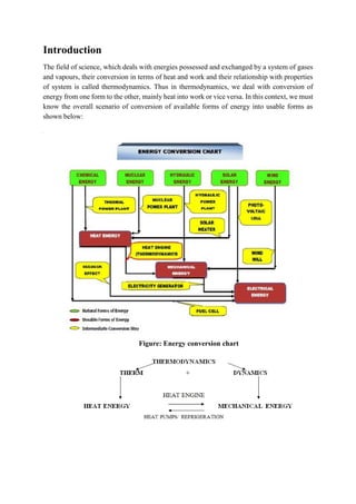
  • 1. Introduction The field of science, which deals with energies possessed and exchanged by a system of gases and vapours, their conversion in terms of heat and work and their relationship with properties of system is called thermodynamics. Thus in thermodynamics, we deal with conversion of energy from one form to the other, mainly heat into work or vice versa. In this context, we must know the overall scenario of conversion of available forms of energy into usable forms as shown below: Figure: Energy conversion chart
  • 2. Application of Thermodynamics  Power Generation (Thermal/Nuclear Power plants)  Automobiles (Petrol/ Diesel/LPG/CNG engines)  Processing Industries (Steam generation, Refrigeration systems)  Gas Compressors (Air compressors) Thermodynamics Definition: Is the science of energy transfer and its effect on the physical properties of substance. Thermodynamics is primarily concerned with two forms of energy i.e. "Heat & Work". It is basically based on four laws of thermodynamics known as zeroth, first, second and third law. Thermodynamic principles are used in the designing of energy converting devices, such as, steam engines, IC. engines, steam and gas turbines, refrigerators, air conditioners, fuel cells etc. Thermodynamic System: It is defined as a definite region or space (area) or a quantity of matter on which attention is focus for the study of work and heat transfer and conversion. Figure: A Thermodynamic System Boundary: It is defined as actual or hypothetical envelope enclosing the system. The boundary may be real or imaginary. It may be fixed or movable in nature. Surrounding : It is defined as the space and matter extremal to the thermodynamic system and outside boundary. Universe: System + Boundary + Surrounding
  • 3. Types of System: 1. Open System: A system is called an open system if the mass as well as the energy transfers and its boundaries. Examples 1. IC engines 2 Turbines 3. Nozzles etc. 2. Closed System: In this type of system no matter or mass may enter or leave across the system boundary, there may be energy (heat or work) transfer across the system boundary Examples 1.A certain quantity of fluid in a cylinder bounded by a piston constitutes a closed system. 2. Thermal power plants Figure 2: Types of Systems 3. Isolated System: Neither mass nor energy transfers can take place through its boundaries. Example Fluid enclosed Insulated in a perfectly insulated closed vessel (Thermos -Flask). Figure 2.1: Types of Systems 4.Adiabatic System: the system which is thermally insulated from its surrounding is called adiabatic system it can power exchange work with the surrounding if it does not, it become an isolated system.
  • 4. Other classification of system: Homogeneous system: system or quantity of mass which consists of a single phase is called homogeneous system. Example mixture of air and water vapor, solution of NH3 in water. Heterogeneous System: A system which consists of two or more phase, called heterogeneous system. Example 1 water and steam 2. ice and water 3 water and oil etc. Phase: A phase is a quantity of matter which is h homogeneous throughout in chemical composition and physical structure. Thermodynamic equilibrium: A system is said to be in a state of thermodynamic equilibrium if the values of the microscopic properties (such as temperature pressure etc.) at all the point are same. thermodynamic equilibrium is a complete equilibrium and it is including the following equilibrium: 1. Mechanical equilibrium there are no unbalanced forces within the system or between the surrounding and system is known as mechanical equilibrium. In this case magnitude of of resultant force is zero. 2.Chemical equilibrium in this equilibrium NO2 chemical reaction take place in the system and the chemical composition which is same throughout the system does not vary with time. 3. Thermal equilibrium the temperature of the system does not change with time and has the same value at the all point in the system its mean temperature gradient is not available or can be considered as zero in thermal equilibrium. 4. Electrical equilibrium If there exist and uniformity of electrical potential throughout the system it can be treated as in electrical equilibrium.
  • 5. Property of substance Any characteristics of a substance which can be observed on major is called property of substance. Example pressure temperature mass specific volume etc. (a) intensive property: these properties do not depend on the mass of the system. Intensive properties are generally denoted by lowercase letter with major exceptions pressure” P” and temperature “T”, which are always intensive. Example temperature (T), pressure (P), specific volume (v), density (ρ) etc. (b) extensive property: these properties depend on the mass of the system. If mass changes, there value also changes. These are generally denoted by upper case letter with major exceptions like mass “m”, number of moles “n”. Examples volume (V), energy (E), total enthalpy (H), entropy (S), potential energy (PE), kinetic energy (KE) etc. The ratio of two extensive property of a homogeneous system is an intensive property. Like ratio of mass and volume is density which is intensive property. when an extensive property is divided by the mass or number of moles of a substance forming the system, the resulting intensive property is called a specific property. Example: specific volume, specific energy etc. State, Change of State, Path, Process, Cycle State: State is the condition of the system at an instant of time as described on measured by it properties for each unique condition of a system. Change of State: Any operation in which one or more of the properties of a system changes is called a change of state. Path: thermodynamic system passing through a series of state constitutes a path. Process: when a system changes its state from one equilibrium state to another equilibrium state, then the path of successive States through which the system has passes is known as thermodynamic process. Cyclic process:
  • 6. cyclic process consists of number of processes incorporated to achieve the target in thermodynamics cycle the initial and final state of process are same. Reversible and Irreversible Process In reversible process, the initial state and final states are same, together with all energy transfer or transfer during the process can be completely restored in both system and surroundings. No heat loss, friction loss and traces of path cannot be observing after reversing the process. In reality no thermodynamic process is completely reversible. Same path and traces can be followed to achieve reversibility. The reversal process having following condition which must be satisfied: 1. The process processed at an extremely slow rate so that it goes inside with the Quasi static process. 2. The system should be free from dissipative forces like friction, inelasticity, viscosity, electrical resistance etc. This is because energy spent against such forces cannot be recovered. 3. No heat, work and friction losses should occur during process. 4. A Reversible process should not leave any traces to show that the process had ever occurred. 5. It should not leave any history behind its mean no change should be created on environment. Figure: (a) Reversible Process (b) Irreversible Process In Irreversible process, If the energy transfer is not restored in both system and surroundings then process is called irreversible. Heat transfer friction losses and traces of path can be observed in irreversible process. All real or natural process are irreversible in nature. In irreversible process same path cannot be followed if try to achieve reversibility. Quasistatic process In thermodynamics, a quasi-static process is a thermodynamic process that happens slowly enough for the system to remain in internal equilibrium. An example of this is quasi-static compression, where the volume of a system changes at a slow rate enough to allow the pressure to remain uniform and constant throughout the system. Quasi means ‘as if/ almost constant’, This process is a succession of equilibrium states and infinite slowness is its characteristic feature. The definition given above is closer to the
  • 7. intuitive understanding of the word “quasi-” (as if) “static” and remains technically different from reversible processes. Only in Quasistatic process can we define intensive quantities (like Pressure, Temperature, Specific volume, Specific entropy) of the system at every instant during the whole process; Otherwise, since no internal equilibrium is established, different parts of the system would have different values of these quantities. Any reversible process is a quasi-static one. However, quasi-static processes involving entropy production are not reversible. Path Function and Point Function Path function A Path function is a function whose value depends on the path followed by the thermodynamic process irrespective of the initial and final states of the process. Their magnitudes depend on the path followed during a process as well as the end states. Work (W), heat (Q) are path functions. An example of path function is work done in a thermodynamic process. Work done in a thermodynamic process is dependent on the path followed by the process. A path function is an inexact or imperfect differential.
  • 8. In the P-V diagram given above we can easily see that for the same initial and final states of the system, work done in all the three process is different. For process A work done is b2A1a For process B work done is b2B1a For process C work done is b2C1a Another example of path function is heat. Point function A Point function (also known as state function) is a function whose value depends on the final and initial states of the thermodynamic process, irrespective of the path followed by the process. Example of point functions are density, enthalpy, internal energy, etc. A point function is a or we can say all the properties of the system are point functions. Point functions are exact or perfect differential. Note: Since a point function is only dependent on the initial or final state of the system, hence in a cyclic process value of a thermodynamic function is zero, or change in thermodynamic property is zero. Difference between point function and path function Sr. no. Point Function Path Function 1 Its values are based on the state of the system (i.e. pressure, volume, temperature etc.) Its values are based on how that particular thermodynamic state is achieved. 2 No matter by which process the state is obtained, its values will always remain the same. Different processes to obtain a particular state will give us different values. 3 Only initial and final states of the process are sufficient We need to know exact path followed by the process 4 Its values are independent of the path followed Its values are dependent on the path followed 5 It is an exact or perfect differential It is an inexact or imperfect differential.
  • 9. 6 Its cyclic integral is always zero Its cyclic integral may or may not be zero 7 It is property of the system It is not the property of the system 8 Its examples are density, enthalpy, internal energy, entropy etc. Its examples are Heat, work etc.
  • 10. Pressure Pressure is the force applied perpendicular to the surface of an object per unit area over which that force is distributed. Gauge pressure is the pressure relative to the ambient pressure. Mathematically: P=F/A where: P is the pressure, F is the magnitude of the normal force, A is the area of the surface on contact. Pressure is a scalar quantity. It relates the vector area element (a vector normal to the surface) with the normal force acting on it. The pressure is the scalar proportionality constant that relates the two normal vectors: Atmospheric Pressure, Gauge Pressure, Vacuum Pressure and Absolute Pressure Absolute Pressure - The actual pressure at a given position is called the absolute pressure, and it is measured relative to absolute vacuum (i.e., absolute zero pressure). Gage Pressure – Gage pressure is the pressure relative to the atmospheric pressure. In other words, how much above or below is the pressure with respect to the atmospheric pressure. Vacuum Pressure – Pressures below atmospheric pressure is called vacuum pressures and are measured by vacuum gages that indicate the difference between the atmospheric pressure and the absolute pressure. Atmospheric Pressure – The atmospheric pressure is the pressure that an area experiences due to the force exerted by the atmosphere. Equations Pgage = Pabs − Patm Gage Pressure Pvac = Patm − Pabs Vacuum Pressure Pabs = Patm + Pgage Absolute Pressure
  • 11. Laws of Thermodynamics The science of thermodynamics is based on the fourth law of thermodynamics namely: 1. Zeroth law of thermodynamics 2. First law of thermodynamics 3. Second law of thermodynamics 4. Third law of thermodynamics These all laws are deducted from experimental observations and are based on logical reasoning. There are no mathematical proof for these laws. Equality of Temperature Any two bodies are said to have 'equality of temperature' when no change in any observable property occurs when they are brought in for thermal communication. The equality of temperature is also termed 'thermal equilibrium'. Zeroth law of thermodynamics: It state that, “if two system are each in thermal equilibrium with third system, then they are also in thermal equilibrium with each other," First law of thermodynamics: First law of thermodynamics is based on law of conservation of energy, which state that "energy can neither be created nor destroyed but it can only be transferred from one form to another form of energy". Statement of the first law of thermodynamics for the closed system undergoing a cycle. " when a system undergoes a thermodynamic close and reversible cyclic process then the net heat supplied to the system from the surrounding is equal to net work done be the system on its surrounding". Its mean "for a closed, and reversible cyclic process integration of energy will always be equal to the integration of work.
  • 12. A closed system can exchange energy with its surroundings through heat and work transfer. In other words, work and heat are the forms that energy can be transferred across the system boundary. Both heat transfer and work transfer may cause the same effect on a system. They both are different forms of energy in transit. Energy that enters a system as heat may leave as work or vice versa. (∑W) cycle = J(∑Q) cycle or, ∮ δW = ∮ δQ Where, J is called Joule’s equivalent. When heat and work both are measured in same unit, value of J will be 1. ∮ δW = ∮ δQ Sign convention The work done by a system on the surroundings is treated as a positive quantity. Similarly, energy transfer as heat to the system from the surroundings is assigned a positive sign. With the sign convention one can write, ∫dQ = ∫dW Corollary A device or machine is impossible, which can produce work continuously without absorbing energy from its surroundings.
  • 13. Consequences of the first law: Suppose a system is taken from state 1 to state 2 by the path 1-a-2 and is restored to the initial state by the path 2-b-1, then the system has undergone a cyclic process 1-a-2-b-1. If the system is restored to the initial state by path 2-c-1, then the system has undergone the cyclic change 1- a-2-c-1. Let us apply the first law of thermodynamics to the cyclic processes 1-a-2-b-1 and 1- a-2-c-1 to obtain ∫1-a-2dQ+ ∫2-b-1dQ - ∫1-a-2dW - ∫2-b-1dW =0 ∫1-a-2dQ+ ∫2-c-1dQ - ∫1-a-2dW - ∫2-c-1dW=0 Subtracting, we get ∫2b1dQ- ∫2c1dQ – (∫2b1dW - ∫2c1dW) =0 We know that the work is a path function and hence the term in the bracket is non-zero. Hence we find ∫2b1dQ = ∫2c1dQ That is heat is also a path function. Energy is a property of the system: By rearranging we can have ∫2b1 (dQ - dW) = ∫2c1 (dQ - dW) It shows that the integral is the same for the paths 2-b-1 and 2-c-1, connecting the states 2 and 1. That is, the quantity ∫ (dQ - dW) does not depend on the path followed by a system, but depends only on the initial and the final states of the system. That is ∫ (dQ - dW) is an exact differential of a property. This property is called energy (E). It is given by dE = dQ-dW E = KE + PE +U where U is the internal energy. Therefore, dE = d(KE) + d(PE) + dU = dQ-dW Quit often in many situations the KE or PE changes are negligible. dU = dQ – dW An isolated system does not exchange energy with the surroundings in the form of work as well as heat. Hence dQ = 0 and dW = 0. Then the first law of thermodynamics reduces to dE = 0 or E2 = E1 that is energy of an isolated system remains constant.
  • 14. First law for a closed system undergoing a change of state Consider a system undergoing a cycle, in which it changes from state 1 to state 2 through a process A and returns from state 2 to state 1 through process Now for a cycle, we have For a cycle made up of two process A and B, Now consider another cycle using process C and B, then Similarly, Now subtracting the second from the first equation, we get On rearranging, Since, A and C represents arbitrary process between states 1 and 2, the quantity is same for all processes between states 1 and 2. Therefore, depends upon only initial and final states, and not on the path followed, so it is a point function and differential of the property of the mass. This property is the Energy of the mass, E. On integration we get, 1Q2 = E2-E1 + 1W2. This is the general expression of first law for a process. The property E represents all the energy contained by the system at given state. If we separate the bulk kinetic energy and potential energy for the property E, remaining all the energy is called the internal energy U, So, E = U + KE + PE In differential form, dE = dU + d (KE) + d(PE) So, first law for change of state may be written as dQ = dU + d(KE) + d(PE) + dW
  • 15. Internal Energy a property Internal Energy (U) U is an extensive property and so is KE and PE. Whereas, KE and PE are the stored macroscopic energy, U is the microscopic energy composed of translational, rotational, vibrational, chemical, electronic, nuclear, etc. energy possessed by the molecules of a substance. It has already been discussed in the first chapter that the internal energy is a property of the system and depends on temperature only. From the first law of thermodynamics as discussed in previous article Q = W + dU If there is a case when heat is supplied to a fix volume of gas (thermodynamic system) confined in fix boundary of the system i.e. there is no change in volume of gas during supplying of heat, then there will not be any work. So W = 0 and dU = Q As Q is heat supplied to gas keeping it at constant volume, it can be calculated as mCvdt. Thus change in internal energy is heat exchanged at constant volume and can be calculated as Change in internal energy per unit mass i.e. Thus internal energy is a property derived from first law of thermodynamics. It accounts for the difference between heat exchange and work exchange and shows that energy cannot be created nor be destroyed. Change in specific internal energy of a system is always calculated as Cvdt i.e. as a function of temperature change. Enthalpy (H) It is also a property of thermodynamic system which is calculated in terms of other properties. It is defined as the sum of internal energy and product of pressure and volume of a thermodynamic system. Thus it is a calculated property and loosely defined as total heat content of the system. It is denoted by H. H = U + PV And dH = dU + d (PV) dH = dU + P.dV + V. dP
  • 16. # First law analysis for a control volume A control volume is a volume in space in which one has interest for a particular study or analysis. Mass, heat and work can cross the control surface and the mass and its properties can change with time in the control volume. # Conservation of mass in control volume The rate of change of mass inside a control volume can be different from zero if we add or take a flow of mass out as Rate of change =( +)in and (–) out For several possible flows, This equation is termed as continuity equation.
  • 17. Non-Flow Reversible Processes (Heating/Cooling and Expansion/Compression of Gases) Until now we have studied that thermodynamic system of a gas is used to convert heat energy into work energy or vice versa which is required in a number of practical applications. Thermodynamic system is also of many types. Here we will study a closed system which can exchange energy with surroundings but not the mass. Thus mass does not flow in or out of the system and so the processes of heating/cooling/compression/expansion etc are undergone by this fix mass of gas confined in continuous closed boundary are called Non-flow processes. In these processes some property of the gas may change and some may not change based on which a particular process is characterized. By applying first law of thermodynamics, the various forms of energy exchange can be calculated considering the processes as reversible i.e. taking all internal/external losses due to friction etc as nil. For this let us consider a fix quantity of an ideal gas filled in a metallic cylinder as shown in below mentioned, one side of which is covered or fixed by a solid end plate and other side is covered by a moving piston. The outer wall of piston matches with inner wall of cylinder such that it makes a leak proof sliding joint. This moving piston makes one of the boundaries of system as moving or flexible. Fig.: Closed system of gas filled in metallic cylinder When infinitely small heat 𝛅Q is supplied to gas from outside through the wall of cylinder, the gas tends to expand and forces the piston weight F to move up. Let piston moves by a short distance, dl. Then the infinitesimal work done can be calculated as = Pressure x Change in volume Total work during a non-flow process 1-2 i.e. compression or expansion of gases can be calculated as taking integral of P.dV
  • 18. All these reversible processes of heat exchange (Heating or Cooling) and work exchange (compression or expansion) by a system of ideal gas with its surroundings can take place in various ways as discussed below: Constant volume heating/cooling process Let the piston is fixed at one point in the walls of cylinder such that volume V = Constant So the ideal gas law PV/T = Constant will reduce to Now let a small increment of heat 𝛅Q is supplied to the gas. As per 1st law of thermodynamics As V = Constant, 𝛅W = P.dV = 0 Thus knowing the values of 𝛅Q and Cv, ∆T (Increase in temperature) can be calculated and so ∆P can also be calculated from above equeation. By measuring the small increment in temperature and pressure of system, the quantity 𝛅Q & ∆U can also be calculated. Constant pressure process Let the piston is free to move in the cylinder and force, F or pressure, P on the piston remains constant. So now the boundaries of the system can move and so the gas can expand or can be compressed i.e. the system is able to exchange work.
  • 19. Now let a small quantity of heat, 𝛅Q is supplied to the gas through the walls of cylinder. On absorbing this heat, the temperature of gas will tend to increase and simultaneously the gas will tend to expand against force F on the piston. Applying 1st law of thermodynamic to this process. Or δQ = P.dV + mCvdT (Eq. 4.7) or Cp = R + Cv or Cp − Cv = R Thus characteristic gas constant of an ideal gas is the difference between specific heat at constant pressure (Cp) and at constant volume (Cv). The ratio of specific heats Cp/Cv is denoted as γ. The physical meaning of R or γ can be taken as the characteristic of an ideal gas to expand under the influence of heat or we can say the increase in product of pressure and volume PV with increase in T. Also by ideal gas law, As pressure, P = Constant, the gas law reduces to V/T = Constant Thus the increase in volume of gas due to expansion and increase in temperature are interrelated and if one can be measured the other can be found and the quantities W, ∆U and so Q can be calculated from equation 4.7 as Constant temperature process (Isothermal Process) The beauty of isothermal expansion or compression process is that the internal energy remains constant and so whole of the heat exchange by system is converted to work and vice versa. However, the process is difficult to visualize while thinking that when the system (gas filled behind piston in the cylinder) absorbs heat, its temperature should always increase. But what happens in the isothermal process that while absorbing heat, simultaneously the gas expands
  • 20. thus decrease in its pressure and temperature takes place and the net change in temperature is zero. While expanding, the gas gives positive work equal to the heat supplied. Conversely also if the gas is compressed by doing extra work on the gas, its pressure and temperature tends to increase, but simultaneously if the gas is cooled in such proportion that the net change in temperature remains zero, the compression process becomes isothermal. In this isothermal compression process, again the work supplied to the gas is given away by the system in the form of heat. Applying first law of thermodynamics to this isothermal process in which dU=0, because dT=0, 𝛅Q = 𝛅W = P.dV From gas law At T= constant Gas law reduces to PV = constant or P1V1 = P2V2 = PV Putting this in equation 4.8 By using this equation, we can calculate the work exchange or heat exchange during isothermal process if we know the change in volume. Also in case of Isothermal process we know that P1V1 = P2V2 Putting in eq. (4.9) By using this equation, we can calculate the work exchange or heat exchange if we know the change in pressure. Adiabatic process
  • 21. Adiabatic process is one in which there is no exchange of heat between system and surroundings i.e. Q= 0. Applying first law of thermodynamics to this process 0 = δW + dU or δW = -dU So, dU = −δW = −P.dV Or in specific terms du = - δw = - P.dv Also from the definition of enthalpy, the change in specific enthalpy is Putting above eq. in each othr dh = vdP Thus in an adiabatic process And dh = CpdT = v.dP Dividing above eq or or Integrating on both sides or or =Constant or
  • 22. or This represents a reversible adiabatic process: 1-2 From gas law or or Putting the value of P1/P2 from equation Thus the overall relation between initial and final properties (Pressure, volume and temperature) in an adiabatic process 1-2 is Work exchange We know that work exchange during a non-flow process is given as W= Thus work during non-flow reversible adiabatic process 1-2 is
  • 23. Specific work i.e. work per unit mass will be If work exchange comes as positive that means gas is doing work on its surrounding during the process and if it comes as negative, the work is being done on the gas. Also in the reversible adiabatic process 1-2, Q = 0 (no heat exchange) so as per first law of thermodynamics: ∆U = -W Or Polytrophic process In real practice it is found that an ideal gas while undergoing a non-flow process which may be any one or combination of two of the heating / cooling and compression / expansion processes, follows the law. PVn = Constant Where n is known as index of compression or expansion. It is a general form of any non-flow process and the value of n decides the particular type of process. For example If n = 0 ↔ then PV0 = constant Or P = constant ↔ constant pressure process. If n = ∞ then PV∞ = constant or P1/∞ .V = constant or P0 V = constant or V = constant ↔ constant volume process If n = 1 then PV1 = PV = Constant. Mixing it with ideal gas law
  • 24. If PV = Constant, then T = constant ⟷ constant temperature process If n = γ then P = Constant ↔ adiabatic process If n has any other value except 0, 1, γ and ∞ ↔ polytrophic process Depending on the value of n, all these processes can be represented on the PV- diagram as follows. Combining the polytrophic process law PVn = Constant with the ideal gas law the relation between initial and final properties (pressure, volume and temperature) in a polytrophic process1-2 can be derived as Heat / work exchange The difference in mathematical law governing an adiabatic and polytrophic process is only of γ and n. So work exchange in a polytrophic process can also be similarly derived as in case of adiabatic process and it will be And specific work, Applying first law of thermodynamics to the polytrophic process 1-2 Q = W + ∆U
  • 25. First law of thermodynamics for control volume For control mass, we have the first law as, as rate equation, we have, Consider a control volume that involves rate of heat transfer, rates of work transfer and mass flows. Since we cannot create or destroy energy, so any rate of change of energy must be caused by rates of energy in or out of the control volume. Since heat and work transfer are already included we need explanation about the energy associated with the mass flow rates. The fluid flowing across the control surface (which envelops the control volume) enters or leaves with an amount of energy per unit mass as, Relating to the state and position of the fluid. Whenever a fluid mass enters a control volume at state i, or exits at state e, there is a boundary movement work associated with that process. Fluid mass enters the control volume as it is pushed by the surrounding against the local pressure with a velocity, giving the control volume a rate of work in the process. So, the flow work, So, the flow work per unit mass is Pv and total ener4gy associated with the flow of mass is, So, first law of thermodynamics for control volume becomes, For, general control volume we may have several (n) entering or (m) leaving mass flow rates so, for that case, the final form or the first law becomes,
  • 26. Steady state steady flow process Control Volume A control volume may involve one or more forms of work at the same time. If the boundary of the control volume is stationary, the moving boundary work is zero, and the work terms involved are shaft work and electric work. Another work form with the fluid is flow work. Flow Work Work is needed to push the fluid into or out of the boundaries of a control volume if mass flow is involved. This work is called the flow work (flow energy). Flow work is necessary for maintaining a continuous flow through a control volume. Consider a fluid element of volume V, pressure P, and cross-sectional area A as shown left. The flow immediately upstream will force this fluid element to enter the control volume, and it can be regarded as an imaginary piston. The force applied on the fluid element by the imaginary piston is: F = PA The work done due to pushing the entire fluid element across the boundary into the control volume is Wflow = FL = PAL = PV For unit mass, wflow = Pv The work done due to pushing the fluid element out of the control volume is the same as the work needed to push the fluid element into the control volume.
  • 27. Steady flow systems The system through which the mass flow rate is constant i.e. Mass Input = Mass Output The state of working substance at any point in this system remains constant. Examples: Most actual thermodynamic equipment work as steady flow system under steady state conditions. Examples are IC engine, Compressors, steam turbines etc. Analysis of steady flow system Under steady state, Total Inlet Energy = Total Outlet Energy Now Total Energy = I.E. + F.E + K.E + P.E Where I.E. = Internal Energy = mu F.E. = Flow Energy = mPv K.E. = Kinetic Energy = 1/2 mV2 P.E. = Potential Energy = mgZ So, In steady flow system the rate of mass flow is constant. i.e. Mass Input = Mass output Or m1 = m2 Figure: Open system Also let the height of working substance at any point in the system remains constant. i.e. z1 = z2. And the kinetic energy is usually so small w.r.t. heat, work & enthalpy term, it can also be neglected. Also taking U1 + P1V1 = h1 (enthalpy) H1 + Q = H2 + W Or Q = dH + W Or dH = δQ - δW Or dU + P.dV + V.dP = dU + P.dV−dW Or V.dP = −dW
  • 28. Here we establish the first law for control volume for the long-term steady operation of devices like turbines, compressors, nozzles, boilers and condensers. SSSF Assumptions 1. The control volume doesn’t move relative to the co-ordinate frame. (No work associated with the acceleration of the control volume.) 2. The state of mass at each point in the control volume doesn’t vary with time. (This implies, 3. The mass flux and its state remain constant with time at the inlets and outlets. 4. The rate of heat and work transfer across the system boundary remains constant. So, according to the assumptions the first law of SSSF devices will be, For models having only one inlet and outlet, the continuity equation becomes, And the first law will be, or,
  • 29. First law applied to SSSF devices: 1. Heat Exchanger It is a Device in which heat from one flowing fluid is transferred to another flowing fluid inside a control volume. In the ideal heat exchanger 1. The fluids flowing will have very low pressure drop 2. There is no means of doing any shaft, electrical etc work through the control volume. 3. Change in K.E. and P.E. of the fluids is very small. 4. No heat transfers to or from the surrounding. So, for the heat exchanger the continuity equation will be, And the energy equation will be, 2. Nozzle: It is a device to generate a high velocity fluid stream at the expense of its pressure. In an ideal nozzle, 1. The fluid pressure will be dropped and velocity increases significantly. 2. Neither Work nor Heat crosses the system boundary. 3. No change in P.E. of the fluid takes place. 4. K.E. at the inlet is usually small and can be neglected. So, the continuity equation will be,
  • 30. And the energy equation will be, 3. Diffuser: It is a device constructed to decelerate a high velocity fluid in a manner that results in a increase in pressure of the fluid (opposite to Nozzle). So, its continuity equation and the energy equation will be same as of the Nozzle. 4. Throttle It is a device in which a fluid flowing in a line suddenly encounters a restriction in the flow passage (may be plate with a hole, capillary tube). In an ideal throttling device, 1. Abrupt pressure drop in the fluid occurs 2. Some increase in velocity will be there but can be neglected because of its very low value. 3. No work, no change in P.E. no heat transfers to or from the surrounding. So, the first law reduces to hi= he So, throttling is a constant enthalpy process. 5. Turbine It is a rotary SSSF Machine whose purpose is the production of shaft work in expense of pressure of the working fluid. In an ideal turbine 1. Change in P.E. and K.E. of the flow are negligible. 2. Heat rejection form the turbine is negligibly small and is undesirable 3. The turbine process is assumed to be adiabatic Hence, the first law reduces to
  • 31. 6. Compressor/ Pump It can be a reciprocating or a rotary device whose purpose it to increase the pressure of the fluid by putting in some shaft work through external means. Devices fulfilling this purpose for liquid are termed Pumps and those for gases are termed Compressors. Theoretically, these devices work exactly in opposite to that of turbine. So, 1. Change in P.E. and K.E. of the flow are negligible. 2. Heat rejection form the turbine is negligibly small and is undesirable 3. The turbine process is assumed to be adiabatic Hence, the first law reduces to 7. Boiler It is a device whose purpose it to increase the pressure of a fluid by putting heat through some external means. In an ideal boiler 1. Change in K.E. and P.E. of the flow are negligible. 2. There will be no work interaction with the surrounding. Hence, the first law for an ideal boiler will be,
  • 32. Uniform State Uniform Flow Process This USUF processes occurs in the devices in which there is provision for change of state of mass of the working fluid. An ideal bottle filling process is an example of USUF process. Assumptions 1. The control volume remains constant relative to the co-ordinate frame. 2. The state of the mass within the control volume may change with time, but at any instant of time the state is uniform throughout the entire control volume. 3. The state of the mass crossing each of the areas of flow on the control surface is constant with time although the mass flow rates may be time varying. The overall USUF process occurs within a span of time t. Continuity equation at any instant of time is; Now integrating over time t, we get, This is the continuity equation for USUF process. Similarly, We have Energy Equation at any instant of time; Since, in USUF process, state within the control volume is uniform at any instant of time, we can write, Now integrating over time t, we get This is the first law of Uniform State Uniform Flow process for period of time t.
  • 33. Perpetual Motion Machine of the First kind (PMM1) A perpetual motion machine of the first kind produces work without the input of energy. It thus violates the first law of thermodynamics: the law of conservation of energy. A perpetual motion machine of the second kind is a machine which spontaneously converts thermal energy into mechanical work. Limitation of the first law of thermodynamics The limitation of the first law of thermodynamics is that it does not say anything about the direction of flow of heat. It does not say anything whether the process is a spontaneous process or not with what amount conversion will take place. The reverse process is not possible. In actual practice, the heat doesn't convert completely into work
  • 34. SECOND LAW OF THERMODYNAMICS, ENTROPY, CARNOT CYCLE Introduction We studied that heat and work are different forms of energy and are convertible in to each other. During this conversion, law of conservation of energy i.e. first law of thermodynamics is followed. But this law has limitation in depicting the fraction of heat energy of a system or supplied to system which can be converted to work. Also it does not specify the conditions under which conversion of heat in to work is possible. Second law of thermodynamics removes this limitation and tells under what conditions, in what direction of heat flow and how much of it can maximum be converted in to work. Thermal Reservoir A thermal reservoir is a large system (very high mass x specific heat value) from which a quantity of energy can be absorbed or added as heat without changing its temperature. The atmosphere and sea are examples of thermal reservoirs. Any physical body whose thermal energy capacity is large relative to the amount of energy it supplies or absorbs can be modeled as a thermal reservoir. A reservoir that supplies energy in the form of heat is called a source and one that absorbs energy in the form of heat is called a sink. Heat Engine It is a cyclically operating device which absorbs energy as heat from a high temperature reservoir, converts part of the energy into work and rejects the rest of the energy as heat to a thermal reservoir at low temperature. The working fluid is a substance, which absorbs energy as heat from a source, and rejects energy as heat to a sink. Thermal Power Plant Q1 = Heat received from hot gases WT = Shaft work by turbine Q2 = Heat rejected to cooling water in condenser WP = Work done on the pump Wnet=WT-WP W = Q1 - Q2 Thermal Efficiency,
  • 35. Reversible Heat Engine Every reversible heat engine operating between the same two temperature reservoirs have identical efficiency. This means no matter how a reversible heat engine is constructed or what the working fluid is, its efficiency is the same as all other heat engines working from the same two temperatures. Refrigerator Refrigerator is a reversed heat engine which either cool or maintain the temperature of a body (T1) lower than the atmospheric temperature (Ta). This is done by extracting the Heat from a cold body and delivering it to a hot body (Q2). In doing so, work WR is required to be done on the system. According to First law of thermodynamics, WR = Q2 – Q1 The performance of a refrigerator is expressed by the ratio of amount of heat taken from the cold body (Q1) to the amount of work required to be done on the system (WR). This ratio is called coefficient of performance. Mathematically, coefficient of performance of a refrigerator, T1 < Ta Heat Pump A refrigerator used for cooling in summer can be used as a heat pump for heating in winter. In the similar way, as discussed for refrigerator, we have Wp =- Q2 – Q1 The performance of a heat pump is expressed by the ratio of the amount of the heat delivered to the hot body (Q2) to the amount of work required to be done on the system (Wp). This ratio
  • 36. is called coefficient of performance or energy performance ratio (E.P.R.) of a heat pump. Mathematically, coefficient of performance or energy performance ratio of a heat pump, From above we see that the C.O.P. may be less than one or greater than one depending on the type of refrigeration system used. But the C.O.P. of a heat pump is always greater than one. Statements of Second Law of Thermodynamics Kelvin-Planck statement It is impossible to construct a thermodynamic system or device which operates in a cycle and produce no effect other than the production of work by exchange of heat with a single reservoir. Or in simple terms it states that all the heat from a single heat reservoir cannot be converted to work.
  • 37. In detail, the meaning of statement is that there is no such device possible which can continuously take heat from heat reservoir on one side and convert all of it into work on the other side. But only a part of heat energy while flowing from high temperature reservoir to low temperature reservoir can be converted to work and the remaining part must be rejected to low temperature reservoir i.e. atmosphere. Therefore, only a part of heat energy while in transition from high temperature to low temperature is possible to be converted in to work. Classius statement This statement is regarding the conversion of work in to heat and it states that (it is impossible to construct a thermodynamic system or device which, while operating in cycle (i.e. working continuously), transfers heat from low temperature reservoir to high temperature reservoir without taking help or absorbing work from some external agency.) In detail, the meaning of statement is that heat can be made to flow from low temperature to high temperature only by applying external work. Heat Engine It is a thermodynamic system or device which can continuously convert heat energy into work energy or we can say thermal energy in to mechanical energy. We know that to work continuously, anything has to operate in a cycle. Therefore, heat engine is also a thermodynamic device operating in a cycle. The performance of a heat engine is measured in terms of its thermal efficiency which is the ratio of work output to heat absorbed by engine, i.e. Where W = Rate of mechanical work done by engine Q = Heat absorbed by engine or rate of heat supplied to engine.
  • 38. Reversible heat engine A heat engine which operates through a reversible cycle is called Reversible Heat Engine. As per second law of thermodynamics, heat engine absorbs heat Qh from a high temperature source, converts a part of it into Mechanical work W and rejects the remaining part of heat Qc to a low temperature heat sink as shown in below mentioned figure If the heat engine is reversible i.e. all its processes are reversible, then it can be operated on the reverse cycle in reverse direction with the same performance. Then it will start taking heat Qc back from low temperature heat source by absorbing same amount of work W from some external agency and reject the sum of heat absorbed and work absorbed in the form of heat Qh to high temperature heat source. This reversed heat engine will be called heat pump as shown in figure. If this heat pump is used for the purpose of extracting heat from a low temperature body, it is called a refrigerator. Corollary of 2nd law of thermodynamics No heat engine operating between two heat reservoirs, always operating at constant temperature, can be more efficient than a reversible heat engine operating between the same temperature limits. Also all types of reversible heat engines operating between same temperature limits will have the same efficiency. It can also be proved with a simple logic. Let us say, there is an irreversible engine having more efficiency than that of a reversible engine operating between same temperature limits. Let irreversible engine produces work Wirr and reversible engine produces work Wrev (such that Wirr>Wrev) by absorbing heat Qh from heat source at temperature Th and rejecting heat Qc to heat reservoir at temperature Tc. Now if we operate reversible engine in reverse direction like a heat pump taking work Wrev from the work produced by irreversible engine and absorbing heat Qc back from heat reservoir at temperature Tc and rejecting back heat Qh to heat reservoir at temperature Th as shown in fig 7.2. We will find that a net positive work, W = Wirr - Wrev should be produced continuously without any
  • 39. effect or any net heat exchanged with reservoirs which is completely opposite to the law of conservation of energy i.e. energy cannot be produced without its expenditure. Figure: Reversible and irreversible heat engines In this way, our assumption that an irreversible engine is more efficient than a reversible engine is totally wrong. Hence Wrev > Wirrev One more fact about a reversible heat engine is that it does not exist in reality. But the idea of reversible heat engine is completely hypothetical in which the heat exchange process is thought as reversible without any change in temperature. Otherwise heat exchanged in a medium is irreversible and taken as Q = m.C.ΔT, m = mass C = Specific heat ΔT = temperature change. When some heat flows from a high temperature body to low temperature body, change in their temperatures occurs i.e. hot body becomes somewhat cool and cool body becomes somewhat hot, but now this heat cannot come back from cold body to hot body i.e. it is an irreversible process. So, with ΔT = 0 i.e. heat exchanged without change in temperature can only be visualized in a way that the heat reservoirs and working medium in the reversible heat engine, which is exchanging heat with heat reservoirs, both are of infinite heat capacity and there is no change in their temperature and the amount of heat exchanged depends on the absolute temperature of reservoirs at which heat is being exchanged i.e. Q ∝ T. So in a reversible heat exchange process happening at constant temperature, heat exchanged is proportional to absolute temperature. This is also named as CLASSIUS statement.
  • 40. Carnot Cycle/Carnot Engine Carnot suggested a reversible cycle comprising of two reversible isothermal heat exchange processes and two reversible adiabatic expansion/compression processes as shown on P-V and T-S charts in Figure. Figure: Carnot cycle Carnot Engine is the reversible heat engine working on Carnot cycle 1-2-3-4 as explained below: Process 1-2: Reversible isothermal heat addition: Heat, Qh is transferred to the working substance from the high temperature reservoir at temperature Th = T1 =T2. The heat transfer is reversible and isothermal. Expansion of gas takes places i.e. heat energy is converted to work but the internal energy of system remains constant. Process 2-3: Reversible adiabatic expansion: During the expansion process, the system is thermally insulated so that Q = 0. The temperature of the working substance decreases from high temperature, Th to low temperature, Tc = T3 = T4. Expansion of gas takes place at the expense of its own internal energy. Process 3-4: Reversible isothermal heat rejection: Heat Qc is transferred from the working substance (gas) to low temperature heat reservoir (sink) at constant temperature Tc. Heat transfer is isothermal & reversible. Gas is compressed by spending of external work and equivalent heat to this work is rejected to heat sink. Internal energy remains constant. Process 4-1: Reversible adiabatic compression: During the compression process, the system is thermally insulated, so Q =0. Temperature of working substance increases from Tc to Th. So internal energy of the system increases by an equal amount to the compression work done on the system. Carnot efficiency An engine operating on the Carnot cycle has maximum efficiency. Now Qh ∝ Th, Absolute temperature of hot reservoir Qc ∝ Tc, Absolute temperature of cold reservoir Thus,
  • 41. Thus, the Carnot efficiency does not depend on the type of working substance but only on the absolute temperature of hot & cold reservoirs. Classius Equality & Inequality As per corollary of 2nd law of thermodynamics all the reversible engines operating between two heat reservoirs at the same temperature, have the same efficiency, irrespective of the working substance used. That means between the temperature th & tc the value of Qh & Qc are always same for any reversible engine. The function f proposed by Kelvin and subsequently accepted is given by the simple relation. Where C is a constant and Th & Tc are the absolute or thermodynamic temperatures on thermodynamic temperature scale. Or or It is called Classius equality for a reversible cycle. In case of an irreversible cycle for a heat engine, Wirrev < Wrev Or Qh - Qirr < Qh Qrev (for the same amount of heat absorbed, Qh in both cases) Or Qc irr > Qc rev Or , which is called Classius inequality. Thus Classius Equality and In- equality statements can be combined in mathematical terms as:
  • 42. Concept of Entropy As the first law of thermodynamics introduces a property named as internal energy. Second law of thermodynamics, when applied to a process, introduces the property named as entropy, which is of extensive type. The physical significance of entropy is somewhat difficult to imagine, but if we start from the very basic, it will definitely give an idea of entropy and also its importance in thermodynamic calculations. Now consider a reversible cycle 1A2B1 having two reversible processes A & B between the states 1 & 2 and another reversible cycle 1A2C1 having two reversible processes A and C between the same states 1 & 2, as shown in fig 7.4. Figure: Reversible cycles Applying Classius equality to reversible cycles 1A2B1 and 1A2C1 From the above two equations: Thus, we see that for any reversible process between state 1 & 2 is same i.e. independent of path followed B or C or any other path (process) and depends only on states 1 & 2. Thus it is a point function and hence is a property called entropy (S), such that a change in this property, Hence change in entropy during a process 1-2 is given as:
  • 43. Thus, entropy of a system may be defined as a property such that change in it from one state to other is always equal to integral of heat exchanged divided by absolute temperature, at which heat is exchanged, during any reversible process between the states. Specific entropy Entropy per unit mass is called specific entropy. It is denoted by small letter s. Conclusion: For a reversible process in a closed system a) Entropy increases if heat is added b) Entropy decrease if heat is rejected c) Entropy remains constant if there is no heat transfer. Third law of thermodynamics: - Unattainability of absolute zero is based on the third law of thermodynamics which states that the entropy of a pure substance of absolute zero temperature is zero. This is also called Nernst Theorem.
  • 44. ENTROPY AND AVAILABILITY Entropy Change for an Irreversible Process in a Closed System First of all, it may be made clear here that, entropy is a property and any change in it between two states is always constant irrespective of the type of process between these states. Let us consider a reversible cycle 1A2B1 formed by two reversible processes A and B between state 1 & 2 and an irreversible cycle 1A2C1 formed by one reversible process A and other irreversible process C between states 1 & 2 as shown in Fig 8.1. Figure: Irreversible cycle Applying Classius equality & inequality to both cycle (1A2B1)rev & (1A2C1)irr 0 From (i) and (ii) It is due to -ve sign otherwise the numerical value of is high. Now Thus for the irreversible process C, change in entropy So even if Q =0 for irreversible process, the entropy will always increase. It can be taken mathematically as Where, δI is the rise in entropy due to irreversibility factor By integrating the total change in entropy during an irreversible process is The effect of this irreversible term I is always to increase some entropy whether the heat is added or rejected or not exchanged.
  • 45. Conclusion For an Irreversible Process 1. If heat is added, entropy increases due to heat addition and irreversibility. 2. If there is no heat transfer, the entropy still increases due to irreversibility. 3. If heat is rejected, entropy decreases due to heat rejection and increases due to irreversibly. Net effect may be +ve or -ve. General mathematical statement for change in entropy between two states is Where = sign is for Reversible process between the given states. > Sign is for Irreversible Process between the given states. It can be understood more clearly with the help of fig as given below: Figure: Relationship of change in entropy with heat exchange during reversible and irreversible processes
  • 46. STEAM AND ITS PROPERTIES FORMATION OF STEAM AND ITS PROPERTIE Introduction to Steam: Steam comes under the category of pure substance. A pure substance is one whose chemical composition does not change with the change of phase during thermodynamic processes. It is a homogeneous substance. A pure substance can exist in three phases: (a) Solid phase as ice (b) Liquid phase as water (c) Gaseous phase as steam When ice melts with the addition of heat, it enters liquid phase to form water. Similarly, when water is heated, it evaporates and liquid phase is converted to steam, which may be called as vapour. During this transformation, known as vaporization, it remains as a two-phase mixture of water and steam. After the completion of vaporization, it remains in gaseous phase as steam. Introduction Steam, which is gaseous form of pure water, is an excellent working medium in various thermodynamic systems because of its following properties: 1) It can carry large quantities of heat 2) It is produced from water which is cheap and readily available 3) It can be used for heating purposes after its duty as working agent is completed. 4) It can be used purely as a heating medium in food processing Industries because of a fast, easily controllable and hygienic method of heating. Formation of Steam In general, steam can be formed by boiling water in a vessel. But to use it effectively as a working or heating medium, it has to produce in a closed vessel under pressure. Steam formed at a higher pressure has higher temperature and can be made to flow easily through insulated pipes from steam generator to point of use. A simple arrangement of formation of steam at constant pressure is shown in figure Consider 1 kg of ice at temperature -100 C which is below the freezing point. Let it be heated at constant pressure P. The temperature of ice starts increasing until it reaches the melting
  • 47. temperature of ice i.e., 00 C and during this course ice absorbs its sensible heat. On further addition of heat, ice starts melting, its temperature remains constant at 00 C and it absorbs latent heat of fusion and converts completely into water at 00 C. On further addition of heat, the temperature of water starts rising until it reaches the boiling temperature or saturation temperature corresponding to pressure P. This heat absorbed by water in sensible heat. Note: Saturation temperature or boiling temperature increases with increase in pressure After the boiling temperature is reached, it remains constant with further addition of heat and vaporization take place. The water absorbs its latent heat and converts into dry saturated steam remaining at same saturation temperature. The intermediate stage of water and dry saturated steam is wet steam, which is actually a mixture of steam and water. If further the heat is added, the temperature of this dry saturated steam starts rising from saturation temperature and it converts into superheated steam. This heat absorbed is again the sensible heat. The total rise in temperature of superheated steam above the saturation temperature is called degree of superheat. We must know here that the saturation temperature, latent heat and other properties of steam remain same at constant pressure but varies with the variation of pressure. Figure: Temperature enthalpy curve of formation of steam at constant pressure Figure: Generation of steam temperature volume diagram A = Sensible Heat taken by Ice B= Latent Heat of Fusion C = Sensible Heat taken by Water D = Latent Heat of evaporation E = Sensible Heat taken by Steam hw = Specific enthalpy of water hf = Specific enthalpy of saturated water hfg = Latent heat of evaporation hg = Specific enthalpy of dry saturated steam hsup = Specific enthalpy of super-heated steam
  • 48.
  • 49. Fig: Various diagram of steam Enthalpy–entropy chart of Steam An enthalpy–entropy chart, also known as the H–S chart or Mollier diagram, plots the total heat against entropy, describing the enthalpy of a thermodynamic system. A typical chart covers a pressure range of 0.01– 1000 bar, and temperatures up to 800 degrees Celsius.
  • 50. Advantages of superheated steam 1) The superheated steam can be considerably cooled during expansion in an engine cylinder, before its temperature falls so low as to cause condensation on cylinder walls which is a direct heat loss. 2) The temperature of superheated steam being higher, it gives a high thermal efficiency in heat engine. 3) It has high heat content and so high capacity of doing work. Thus it results in an economy in steam consumption. Enthalpy of Steam To find out the total heat content or enthalpy of any state of water/ steam we have to add all types of heat added i.e., sensible and latent to convert the water to that state starting from some initial state or datum which is assumed as a zero enthalpy point or where the heat content is taken as zero. Generally, in engineering calculations the datum is water at 00 C where it is considered as having zero heat content or zero enthalpy. Enthalpy of one kg of water or steam is called as specific enthalpy. Specific enthalpy of un-saturated water (hw) It is simply the amount of heat required to raise the temperature of one kg of water from 0 ℃ to its actual temperature which is below its saturation temperature. It can be calculated by multiplying actual temperature of unsaturated water with its specific heat which is considered equal to 4.187 kJ/ kg/ K. It is denoted as hw. Where t is the temperature of water in o C Note: If water is present at a temperature below its boiling point or saturation temperature, it is called unsaturated water. If water is present at its boiling point i.e. saturation temperature, it is called saturated water. Specific enthalpy of saturated water (hf) It is the quantity of heat required to raise the temperature of one kg of water at 00 C to its boiling point or saturation temperature corresponding to the pressure applied. It is denoted as hf. It can be calculated by multiplying the specific heat of water to the total rise in temperature. The specific heat Cpw of water may be approximately taken as constant i.e., 4.187 kJ/kg K, but in actual it slightly increases with increase in saturation temperature or pressure. Thus hf = Cw (ts 0) = Cpts Where, ts = Saturation temperature Latent heat of steam (hfg) Latent heat of steam at a particular pressure may be defined as the quantity of heat in kJ required to convert one kg of water at its boiling point (saturated water) into dry saturated steam at the same pressure. It is usually denoted by L or hfg. It decreases with increase in pressure or saturation temperature. Wet and dry steam Wet steam is that steam in which the whole of water has not vaporized but the un- vaporized water is present in the form of mist/fog suspended in completely vaporized water or steam. Due to this mist the wet steam is visible. However, the dry steam i.e., in which the vaporization is complete is invisible or colorless. Any steam which is completely dry and present at saturation temperature is called dry saturated steam.
  • 51. Dryness fraction This term refers to quality of wet steam. It is defined as the ratio of the weight of dry steam actually presents to the weight of total wet steam which contains it. It is denoted by x. Thus Where Wd = Weight of dry steam in 1 kg of wet steam, W = Weight of water in suspension in 1 kg of wet steam Dryness fraction is zero for saturated water and one for dry saturated steam. Wetness fraction It is the ratio of the weight of water/ moisture in suspension in a wet steam sample to the total weight of wet steam. It is calculated by subtracting x from 1 Wetness fraction is 1 for saturated water and 0 for dry saturated steam. Specific enthalpy of wet steam (hws) It may be defined as the quantity of heat required to convert 1 kg of water at 00 C into wet steam of a given quality and at constant pressure. It may be denoted by hws. It is equal to the sum of specific enthalpy of saturated water and latent heat of dry fraction of steam. So hws = hf + x. hfg Specific enthalpy of dry saturated steam (hg) It may be defined as the quantity of heat required to convert 1kg of water at 00 C into dry saturated steam at given constant pressure. It may be denoted by hg. It is equal to the sum of specific enthalpy of saturated water and latent heat corresponding to given saturation pressure and temperature. Thus hg = hf + hfg Specific enthalpy of superheated steam (hsup) It is defined as the quantity of heat required to convert 1kg of water at 00 C into the superheated steam at given temperature and pressure. It may be denoted as hsup and is equal to the sum of specific enthalpy of dry saturated steam and product of specific heat of superheated steam (Cs) to degree of superheat. hsup = hg + Cs(tsup - ts ) Where, hg and ts are the specific enthalpy of dry steam and saturation temperature at corresponding pressure and CS & tsup are specific heat of superheated steam and temperature of superheated steam at the same pressure. The superheated steam behave like the perfect gas and law of expansion has been found to be pv1.3 = constant. Specific Volume of Water/Steam The volume of a unit mass of water/steam is known as its specific volume
  • 52. Specific volume of saturated water (vf) It is defined as volume of 1kg of water at saturation temperature corresponding to the given pressure. It is denoted by vf. It can be calculated experimentally. It slightly increases with increase in saturation temperature and hence the pressure. The reciprocal of sp-volume is equal to density. Specific volume of dry saturated steam (vg) It is defined as volume of 1kg of dry saturated steam corresponding to the given pressure. It is denoted by vg and can be calculated experimentally. As dry saturated steam is a gas, its specific volume decreases with increase in pressure or the saturation temperature. Specific volume of wet steam of quantity x It is the volume of 1kg of wet steam and is denoted as vws= x.vg+ (1-x) vf At low pressure the value of vf is very small as compared to vg; so the term (1-x) vf may be neglected. Then volume of 1kg of wet steam = x.vg Specific volume of Superheated Steam (vsup) It is the volume of 1kg of superheated steam and can be determined by assuming that the steam behaves as a perfect gas i.e., obeys the gas laws. It is denoted by vsup Let P = pressure under which steam is superheated. tsup =temperature of superheated steam vg = Specific volume of dry saturated steam ts = saturation temperature at pressure P. Since, P = constant, so Entropy of Steam Specific entropy of saturated water (sf) The specific entropy of saturated water at a particular pressure P and saturation temperature Ts is given as the change in entropy during conversion of one kg of water at 00 C into saturated water at that pressure. The water at freezing point 00 C or 273 K is considered as datum where, absolute entropy is taken as zero. If CW is specific heat of water then the change in entropy of 1kg water during temperature change from 273 K to T K is given as As the Initial entropy at 273 K is zero, so this change in entropy above 273 K is taken as entropy of water at temperature T. In case of Saturated Water, T= Ts. Change in specific entropy during evaporation, (sfg) During evaporation heat added = hfg = Latent heat of water Temperature remains constant during evaporation and is equal to saturation Temperature Ts. Specific entropy of dry saturated steam (sg)
  • 53. It is the entropy of one kg of dry saturated steam and is given as the sum of entropy of 1kg of saturated water and entropy change during evaporation. It is denoted by sg. Thus sg = sf + sfg Specific entropy of wet steam Specific entropy of wet steam is equal to sum of specific entropy of saturated water and change in specific entropy during evaporation of dry fraction of steam. It is denoted by sws sws = sf + x. sfg Specific entropy of superheated steam (ssup) It is the sum of specific entropy of dry saturated steam and entropy change during superheating from saturation temp Ts to superheated temp Tsup. Total specific entropy of superheated steam USE OF STEAM TABLES & MOLLIER CHART, NUMERICAL PROBLEMS Steam Table All the previously mentioned properties of steam i.e. specific enthalpy, specific volume and specific entropy each of saturated water and steam (wet, dry & superheated) vary with the change in saturation pressure. And for a particular saturation pressure there is a fix value of saturation temperature. These properties are required in thermo dynamic calculations where steam is used as working medium. It is quite cumbersome to calculate each time, the value and relation between various properties. So, these are experimentally determined and presented in the form of tables showing value of each property w.r.t either saturation temperature or saturation pressure. These tables are called steam tables. The value of properties of saturated steam and superheated steam are given separately. If any given pressure falls in between two values given in table then value of concerned property on this pressure may be calculated by interpolation. The column in the steam table showing properties of saturated stream are as given below: Table: Stem table format Absolute Pressure in bar (P) Saturation Temperature in 0C (t) Specific Volume in m3/kg Specific Enthalpy in kJ/kg Specific Entropy in kJ/kg.k Water (vf) Steam (vg) Water (hf) Evaporation (hfg) Steam (hg) Water (sf) Evaporation (sfg) Steam (sg) Enthalpy-Entropy Diagram or Mollier Diagram (H-∅)
  • 54. It is a plot of enthalpy on ordinate and entropy on abscissa scale. Constant pressure, constant volume and constant temperature lines are also drawn on it. Fig. Mollier chart Saturation Line or saturation vapour line is also clearly shown as dark red line. This chart is frequently used to show the expansion or compression and heating or cooling of steam, when it is used as a working media in steam engines/turbines. But as far as a dairy or food processing industry is concerned, steam is used only for the purpose of heating and not as a working media. Thus expansion or compression processes of steam are not required, so use of Mollier chart is limited here. In the heating applications, we are mainly concerned with calculating the enthalpy of steam or heat required to prepare steam of required quality. This purpose is solved with the help of steam tables only. So, in the numerical problems mentioned in this lesson, we will be using steam tables only. Numerical Problems 1. Calculate the total heat of 5 kg of steam at an absolute pressure of 8 bar having dryness fraction of 0.8. Also calculate heat in kJ required to convert the steam into dry and saturated steam. Solution From steam tables At pressure 8 bar, hf = 720.9 kJ/kg hfg = 2046.5 kJ/kg hg = 2767.4 kJ/Kg Sp. enthalpy of wet steam
  • 55. hw = hf + x.hfg = 720.9 + 0.8 x 2046.5 = 2358.1 kJ/kg Total heat of 5 kg steam = weight of steam x Sp. Enthalpy = 5x2358.1 = 11790.5 kJ (Ans) Now total heat of 5kg dry saturated steam = 5x hg = 5x 2767.4 = 13830 kJ Net heat required to be supplied for conversion of wet steam into dry saturated steam = 13830 11790.5 = 2039.5 kJ (Ans) 2. 4 Kg of 0.5 dry steam at 6.0 bar pressure is heated, so that it becomes (a) 0.95 dry at 6.0 bar pressure or (b) Dry & saturated at 6.0 bar or (c) Superheated to 300o C at 6.0 bar or (d) Superheated to 250o C at 8.0 bar Using steam tables determine in each case the quantity of heat required to be supplied. Take Csup for superheated steam as 2.3 kJ/ kg K. Solution: Initial Condition of steam are mass, m = 4 kg; x1= 0.5 and P = 6.0 bar So initial enthalpy (total heat content) of 4kg steam is H1 = 4[hf +0.5hfg] [Sub Eq. (i)] From steam table, at 6.0 bar pressure value of specific enthalpy of saturated water, hf and latent heat of steam, hfg are given as hf = 670.4 kJ/kg hfg = 2085.1 kJ/kg Putting these values in equation (i) H1 = 4[670.4+0.5-2085.1] = 6851.8 kJ ≈ 6852 kJ Heat Supplied Case I Final Conditions of Steam are x2=0.95 and pressure, p=6.0 bar. So final enthalpy of steam is H2 = 4[hf + x.hfg] = 4[670.4 + 0.95 - 2085.1] = 10605 kJ Net heat supplied = Final Enthalpy - Initial Enthalpy = H2 - H1 = 10605 - 6852 = 3753 kJ (Ans) Case II Final Conditions of Steam are pressure, p=6.0 bar. Condition is dry saturated i.e., x2 = 1. So final enthalpy of steam is H2 = m.hg = 4*2755.5 kJ/kg [From Steam Table] =11022 kJ Net heat supplied = Final Enthalpy - Initial Enthalpy = H2 - H1 = 11022 - 6852 = 4170 kJ (Ans) Case III Final Conditions of Steam are pressure, p=6.0 bar, Superheated to 3000 C. Form steam tables, saturation temperature, tS at given pressure 6.0bar is ts = 158.80 C. So final enthalpy of superheated steam is H2 = m [hg + CPs (tsup -ts)] = 4[2755.5 + 2.3(300-158.8)] = 12321 kJ So Net heat supplied = Final Enthalpy - Initial Enthalpy = H2 - H1 = 12321 - 6852 = 5469 kJ (Ans) Case IV Final Conditions of Steam are pressure, p=8.0 bar, Superheated to temperature, tsup = 2500 C. From steam tables At 8.0 bar pressure ts = 170.40 C, hg = 2767.4 kJ/kg
  • 56. So H2 = m [hg + CPs (tsup -ts)] = 4[2767.4 + 2.3(250-170.4)] = 11801.92 ≈ 11802 kJ Heat Supplied = H2 - H1 = 11802 - 6852 = 4950 kJ [Ans] 3 Calculate the entropy and volume of 4.73 kg of superheated steam at pressure 7.8 bar and temperature 240o C. Take Cp for superheated steam = 2.32 kJ/kg. K Solution At 7.8 bar Saturation temperature ts = 169.4o C or Ts = 169.4+273 = 442.4 K vg = 0.2461 m3 / kg sg = 6.668 kJ/kg K tsup = 240o C so, Tsup = 240 + 273 = 513 K Sp.vol. of superheated Steam = 0.2854 m3 /kg Total volume of 4.73 kg of steam = 4.73*0.2854 = 1.3498 m3 Sp. entropy of superheated steam = sg + = 7.0115 kJ/ kg K Total entropy of steam = 4.73x 7.0115 = 33.16 kJ/ K (Ans) 4 A boiler is producing steam at a pressure of 15 bars and quality as 0.98 dry. It was observed that while flowing from boiler to the place of heating through pipes, steam looses 20 kJ of heat per kg. Assuming the constant pressure, while flowing through pipe line, calculate the quality of steam at the place of heating. Solution Given conditions of steam in boiler are Pressure P=15 bar; x= 0.98; Heat loss= 21 kJ/ kg From steam tables, we find that At pressure, P=15 bar, hf = 844.6 kJ/kg and hfg = 1945.3 kJ/kg So specific enthalpy of steam in boiler, h1 = hf + x.hfg = 844.6 + 0.98 1945.3 = 2751 kJ/kg Heat loss = 21 kJ/kg So net enthalpy of steam at the other end of pipe line or at the place of heating = 2751−21 = 2730 kJ/kg To find dryness fraction of this steam x2 we know that enthalpy is h2 = hf + x2.hfg or 2730 = 844.60 + x2 * 1945.3
  • 57. 5 In a conical process vat a batch of 50 kg of milk initially at a temperature of 250 C is to be boiled at atmospheric pressure until concentrated to a final mass of 40 kg. Calculate the mass of steam consumed to carry out the process if steam is supplied in dry saturated condition at a gauge pressure of 1 bar and condensate outlet is at 1000 C. Assume 20% of useful heat loss in the vat. Solution Sensible heat absorbed by milk = 15900 kJ Mass of water evaporated from milk = 50-40 = 10 kg Latent heat of evaporation of water at atmospheric pressure = 2257 kJ (from steam table) Latent heat of evaporation of 10 kg water = 10 * 2257 = 22570 kJ Total heat consumed in the process = 15900 + 22570 = 38470 kJ Now, Absolute pressure of steam supplied = 1.013 + 1 = 2.013 bar Enthalpy of dry saturated steam at 2.013 bar pressure = hg = 2707 kJ/kg (from steam table) Enthalpy of condensate at 1000 C = hf = 419.1 kJ/kg (from steam table) Net heat supplied by one kg steam = 2707 - 419.1 = 2287.9 kJ Taking 20 % loss in the process Net heat given by steam to milk = 2287.9 * 0.8 = 1830.32 kJ/kg Steam consumed to supply total heat required in the process as given in equation (1). = 21 kg (Ans)
  • 58. STEAM GENERATORS CLASSIFICATION AND PERFORMANCE PARAMETERS OF BOILERS/ STEAM GENERATORS Introduction Steam generator is a device or equipment which burns the fuel and facilitates the exchange of heat produced to the water to generate required quantity and quality of steam. Thus it is a heat exchanger which has the place for burning of fuel and flow of hot flue gases produced and also has space for storing of water and steam. As steam is produced & stored at high pressure than the atmospheric pressure, steam generator is also a pressure vessel. To handle the hot flue gases and to keep high pressure steam, certain other mountings and accessories are also required for its safe and efficient operation. In this way steam generator is not simply a vessel to boil water but it is a complete unit performing the complete task of producing & handling the high pressure steam by burning of the fuel and exhausting the flue gases efficiently and safely. Most of the boilers are actually a type of shell & tube type heat exchangers. Classification of Steam Generators Depending on the construction and operation, steam generators or commonly named as boilers are classified on the basis of: (a) Alignment of axis of boiler: Boilers are classified as Horizontal, Vertical and Inclined type boiler. Horizontal boiler occupies more floor area but is easily accessible for inspection and maintenance. Vertical boiler occupies less floor area but difficult to access and clean. In a dairy processing plant, we generally find horizontal type boiler. (b) Flow of water and hot flue gases through the boiler: Boilers are broadly classified as fire tube and water tube boiler. This is the first major classification of boilers. Most of the boilers are actually shell and tube type heat exchangers in which one fluid i.e. either water or hot gas flows through the shell and other through the tubes. In a boiler, if fire flows through tubes and water remains in the shell, it is called fire tube boiler. Conversely if water flows through tubes and fire or hot flue gases pass through the shell it is called water tube boiler. In a dairy processing plant, fire tube boilers are generally used due to low pressure requirement, comparatively safe, less operational cost and easy to maintain type characteristics. (c) Location of furnace or burner: Boilers are classified as: Externally fired and internally fired. If fuel is burnt outside the boiler and after burning only, hot flue gases are forced to flow through boiler, it is called externally fired. e.g. Babcock & Wilcox boiler, Sterling boiler etc. If the furnace is located inside the boiler itself, it is called internally fired boiler e.g. Cochran boiler, Lancashire boiler etc. (d) Mode of water circulation: Boilers are classified as forced circulation and natural circulation boilers. If the water flows through boiler by the force of pump, it is called forced circulation boiler. If water flows due to natural current produced, it is called natural circulation boiler.
  • 59. (e) Pressure of steam produced: Boilers are classified as high pressure and low pressure boilers. Above 80 bar pressure, boilers are called high pressure boilers and below this limit, boilers are called low pressure boilers. In a dairy processing plant where steam is used only for heating purpose and not to produce any mechanical work, low pressure boilers are used. High pressure boilers are used in applications where steam is used as a working agent like in thermal power plants etc. High pressure boilers are Benson, Babcock & Wilcox, and Lamont etc. Low pressure boilers are Cochran, Cornish, Lancashire & Locomotive boilers. Table: Comparison between fire tube and water tube boilers S.No Fire Tube Boilers Water Tube Boilers 1. Hot gases flow through tubes or flues passing through water stored in the shell Water flows through tubes passing through the passage of the flue gases. 2. Steam production rate is less i.e. upto 9 tons / hour Steam production rate is high. It can be upto 450 tones/hour. 3. Steam pressure is limited to 25 bar approx. Steam pressure is generally in the range of 125 bar or even more in high pressure or super critical boilers. 4. Due to low pressure and less production rate of steam, their use is generally limited to processing plant or small size power plants used in private industries. Due to high pressure and high production rate of steam, these are commonly used in large capacity power plants like thermal plants for power generation. 5. Chances of bursting are less but in case of bursting, a great damage to the life & property occur. It is because the main shell is under pressure and whole shell bursts. Chances of bursting are more due to high pressure, but the damage is not so severe as in case of fire tube boilers. 6. Feed water treatment is necessary but not so critically required because small deposit in the boiler shell does not deteriorate much the performance of boiler. Feed water treatment is critical and highly essential as even a small deposit in boiler tube may cause overheating and bursting. 7. Construction is more complicated. It occupies more floor area. Transportation is difficult. Because it comes in assembled position. Hence overall cost is high for a unit steam production rate. Construction is simpler. It occupies less floor area. Transportation is not difficult because it can be easily dismantled & assembled. Overall cost is less for a unit steam production rate. 8. Overall efficiency is upto 75%. Overall efficiency with economizer is 90% 9. It can cope up with fluctuating load. It can also bear fluctuating load but only for a shorter period. 10. It takes time to produce steam and increase the steam pressure at a slower rate. It produces steam fast and so increases the steam pressure at a faster rate.
  • 60. Cochran Boiler It is a best example of vertical fire tube boiler and has a very simple construction. It is internally fired multi tubular and natural circulation boiler. Its working can be well understood with the help of below mentioned diagram: Figure: Cochran boiler Description: Cochran boiler has a vertical cylindrical shell with dome shaped top used as steam space. Furnace is a single piece construction situated at the bottom of the shell. The fuel (coal) is burnt on the grate by supplying air naturally through fire hole. Hot flue gases produced are directed through fire brick lining to the horizontal fire tubes surrounded by water filled in the shell. After exchanging their heat with water flue gases are directed to atmosphere through smoke box and chimney. Ash collects below the grate in the ash pit from where it is periodically removed. The various boiler mountings are also installed over the boiler shell. Babcock & Wilcox Boiler It is a simple water-tube boiler and used where higher steam pressure and higher steam production rate is required. It can be used for stationary and marine purposes. The construction is as shown in It consists of a horizontal shell supported on the masonry structure. The shell is connected to two headers on both ends, which are at different level and connected by a number of inclined
  • 61. tubes. When shell remains filled with water, up to the desired level, the headers and tubes also remain filled with water. The tubes are inclined at an angle of 150 and remain suspended/ supported inside the closed furnace/flue gases space. The flue gases produced from burning of the fuel are directed over the tubes in between the baffles forming the zig-zag flame passage. Steam is produced inside the inclined tubes and lifts through the top header and collects in the steam space of the boiler shell. Water from the bottom header comes in place of steam. Water level is checked by level indicator and maintained by feed pump. The boiler shell & tubes are hung by means of wrought iron girders supported on pillars. This arrangement allows the drum and tubes to expand or contract freely. Boiler Terms (i) Boiler Shell: It is a cylindrical shaped structure fabricated with steel plates rolled & riveted or welded together. (ii) Grate: It is a Cast Iron platform in the furnace of boiler on which fuel is burnt. Fuel is coal or wood or any other solid fuel which rests on the perforated surface of grate made of C.I. bars. Air can easily pass through perforated surface from the bottom and also after burning, ash can fall down itself easily. (iii) Furnace/Fire box: It is an enclosed space where fuel is burnt and hot flue gases accumulate. From the furnace, flue gases are directed to flow through the boiler. (iv) Water Space: Volume occupied by water in the boiler is termed as water space which is maintained at a constant level with the help of water level indicator fitted on boiler shell. (v) Steam Space: It is volume occupied by steam over the water surface in boiler. As steam is light, it lifts up and remains in the steam space at the top end of the boiler. (vi) Boiler Mountings: Various fittings on the boiler like pressure gauge, safety valves etc which are necessary for its safe and efficient operation are called Boiler Mountings. (vii) Boiler Accessories: The integral parts of boiler which are required to enhance its efficiency or for overall performance are called accessories e.g. super heater, economizer, feed pump etc. (viii) Foaming: The formation of bubbles on the surface of boiling water is called foaming. (ix) Scale: The deposits of water salts and foreign particles on the heating surface in the form of a hard layer or film is called scale. (x) Blowing off: The suspended impurities in the boiler water usually settle down and are thrown out through a cock due to pressure difference inside and outside the boiler. This process is called blowing off and the cock used is called blow-off-cock. (xi) Lagging: The insulation block mode or rope made of asbestos or magnesia wrapped or fixed outside the boiler shell and steam pipe are called lagging. (xii) Refractory: The fire bricks or clay having low thermal diffusivity are used in the furnace walls and other passages of flue gases where flue gases should retain their heat i.e. where heat loss of flue gases is to be prevented. Boiler Start-up procedure i. Check maximum permissible working pressure which is indicated by a red line on pressure gauge fitted. ii. Check and close drain valves. iii. Open water and steam cocks of water gauge glass and shut its drain cock. iv. Clean and examine filter in feed water system. v. Open feed water tank outlet valve, and ensure water level in tank is at least half the gauge glass. vi. Check fuel oil daily service tank level and drain off any water present. vii. Clean and examine filters in fuel oil system.
  • 62. viii. Shut main steam stop valve and open air vent. ix. Switch on power supply. Feed water pump will automatically supply water to boiler till approximately half gauge glass. x. Fuel oil pump will automatically start. Fuel oil, if heavy diesel oil, will circulate through fuel oil heater till the desired operating temperature is reached. xi. The blower motor will start and purge furnace for at least 1-2 minutes to clear any combustible gas accumulated in the furnace and avoid a blow back. xii. The burner will be ignited according to an automatic sequence, initially at low fire rate. xiii. When steam comes out form air vent, shut off air vent and switch to high fire rate. Steam pressure will gradually increase to normal working pressure. xiv. Check gauge glass, safety valve, and all automatic safety devices to ensure they are functioning normally. xv. Open steam valve very slowly to permit warming through and draining of the cold steam pipes to avoid damage due to water hammer. Performance of Boilers Equivalent evaporation It is defined as the weight of saturated water at 1000C evaporated to dry and saturated steam at 1000C by utilizing heat at the same rate as would have been used under the actual working conditions. If H = Total heat of steam at given working pressure in kJ/kg Hw1 = Total heat of feed water in kJ/kg L = Latent heat of steam at atmospheric pressure = 2257 kJ/kg Wa = Weight of steam produced per hour at given working pressure per kg of fuel We = Equivalent evaporation in kg per kg of fuel Then as per the above definition, We * L = Wa (H - Hw1) Or = Wa .F, where F = f= Factor of Evaporation Factor of evaporation It is a quantity which when multiplied by the actual amount of steam generated at a given pressure from water at given temperature, gives the equivalent evaporation. Equivalent Evaporation = F x Actual Evaporation Thus factor of evaporation may also be defined as ratio of Equivalent Evaporation to actual Evaporation. Boiler efficiency It is the ratio of heat actually utilized in generation of steam in a given period to the heat supplied by fuel in the same period or it is the ratio of heat utilized in generation of a given quantity of steam to the heat supplied by fuel burnt to produce this steam. Where C = calorific value of fuel in kJ/kg and Wf = weight of fuel per hour.
  • 63. Boiler efficiency is always less than 1 because of some loss of heat through hot gases escaping to atmosphere and also directly to atmosphere by conduction convection and radiation. Boiler horse power This term is although not justified in the boiler as it is not producing any mechanical work/power; even then it is adopted by American Society of Mechanical Engineers as standard of measurement of capacity of boiler. One boiler horse power means evaporation of 15.653 kg of water per hour from and at 100o C into dry saturated steam at 100℃. Or a boiler generating 15.653 kg of equivalent evaporation per hour means developing one boiler H.P. Numerical Problems 1. A boiler evaporates 3.6 kg of water per kg of coal burnt into dry saturated steam at 10 bar pressure. The temperature of feed water is 32o C. Find the equivalent evaporation from and at 100o C as well as factor of evaporation. Solution Mass of steam produced, ms = 3.6 kg/kg of coal Initial temperature of feed water, tw = 320C So, Enthalpy of feed water, H1= m.cp.tw = 3.6 * 4.187 * 32 = 482.34 kJ Enthalpy of dry saturated steam produced H2 = m. hg At 10 bar pressure, the value of hg from steam tables is = 2776.2 kJ/kg So, H2 = 3.6 * 2776.2 = 9994.3 kJ Hence the heat supplied to steam per kg of coal burnt in the boiler is H2 - H1= 9994.3 - 482.3 = 9512 kJ Equivalent Evaporation of Boiler (Ans) 2.The following readings were obtained during a boiler trial of 6 hour duration Mean Steam Pressure = 12 bar Mass of steam generated = 40000Kg Mean dryness fraction = 0.85 Mean feed water temp = 30o C Coal Used = 4000kg Calorific value of coal = 33400 kJ/kg Calculate: (1) Factor of equivalent evaporation (2) Equivalent evaporation (3) Efficiency of boiler Solution Mass of steam produced in 6 hours duration = 40000 Kg Mass of coal burnt in 6 hours duration = 4000kg Thus mass of steam produced per kg of coal
  • 64. Now specific enthalpy of feed water at temperature 30o C h1 = Cpt = 4.187 * 30 = 125.6 kJ/kg Specific enthalpy of steam produced at 12 bar pressure and dryness fraction 0.85 h2 = hf + x hfg Now at 12 bar pressure value of hf and hfg from Steam Tables are hf = 798.4 kJ/kg hfg = 1984.3 kJ/kg Putting in above equation h2= 798.4 + 0.85 * 1984.3 = 2485 kJ/kg = 1.045 (Ans) Equivalent Evaporation = mass of steam x Factor of Evaporation = 10 x 1.045 = 10.45 kg/kg of coal burnt (Ans) Efficiency of boiler,
  • 65. BOILER MOUNTINGS AND ACCESSORIES Boiler Mountings These are the fittings, which are necessarily mounted on the boiler itself and mandatorily required for the safe and proper operation of boiler. Various boiler mountings are being discussed here one by one. Water level indicator Function Water level indicator is fitted outside the boiler shell to indicate the water level in the boiler through a glass tube. In any type of boiler, water should remain at the designed level. If the water falls below the level due to change of phase into steam and simultaneously fresh water does not fill in by some reason, the hot surface may expose to steam only and overheat. This is because the heat transfers co-efficient of steam is very less as compared to water. Due to overheat, damage of tube surface may occur. To avoid this situation, level of water in the boiler needs to be constantly monitored & maintained by boiler operator by keeping watch on water level indicator. Construction As shown in the figure two horizontal tubes made of gun metal extend from the boiler shell in such a way that top one is connected to steam space and bottom one is connected to water space of the boiler. These are connected at the other end by a vertical glass tube contained in a hollow casting in such a way that water and steam come out in the glass tube and their interface is visible through it. Each gun metal tube is also provided with a cock to control the flow of water/steam to the glass tube. One drain cock is fitted at the bottom for cleaning purpose. The horizontal metal tubes also contain one metal ball each which normally rests on a hemispherical groove in the tubes. In case the water/steam rush with high speed as may be if glass tube breaks by accident, this ball lifts up from its normal position and block a hole which connects the metal tube with glass tube and stops the flow. Working Working of water level indicator or water gauge is very simple. When the cocks are opened, boiling water and steam from the boiler shell flow into the hard glass tube and maintain the
  • 66. same level as in the boiler which is visible to operator. When the water level falls down beyond a safe limit, operator may switch on the feed pump to fill more water in the boiler shell. In the water and steam passages in the gun metal tubes, a metal ball rest in the cavity made in the passage. In case of breakage of glass tubes by accident, water and steam contained at high pressure in the boiler rush with high speed towards broken glass tube due to large pressure difference between inside and outside of boiler. Due to this, the ball resting in the cavity made in the passage lifts and rushes towards the end of gun metal tube and blocks the passage of steam or water flow. Then immediately the cock can be closed and glass tube can be replaced safely. Pressure Gauge Function A pressure gauge is used to indicate the pressure of steam in the boiler. It is generally mounted on the front top of the boiler. Pressure gauge is of two types as (i) Bourdon Tube Pressure Gauge (ii) Diaphragm type pressure gauge. Both these gauges have a dial in which a needle moves over a circular scale under the influence of pressure. At atmospheric pressure it gives zero reading. Some gauges indicate only the positive pressure but some are compound and indicate negative pressure or vacuum also. Looking at the gauge, boiler operator can check the safe working pressure of the boiler and can take necessary steps to keep the pressure within safe limits. If pressure increases and crosses the safe limit due to any reason, the boiler shell material may fail and it can burst causing damage to life and property. Thus it is very important to constantly monitor pressure in a boiler with the help of pressure gauge. Construction & working A bourdon tube pressure gauge is normally used, the construction of which is shown in the figure The bourdon tube is an elliptical spring material tube made with special quality bronze. One end of tube is connected to gauge connector and other end is closed and free to move. A needle is attached to the free end of tube through a small gear mechanism. With the movement of tube under pressure, needle rotates on the circular scale. The movement of tube & hence needle is proportionate to the rise in pressure and so calibrated with scale.
  • 67. The pressure gauge connector is attached to the boiler shell through a U-tube siphon and three way cocks. In the U-tube, condensate remains filled and so live steam does not come in direct content of bourdon tube but it pushes or exert pressure on the condensate which further stretch bourdon tube. Steam is not allowed a direct contact with the gauge due to high temperature effect on the pressure recording. The three-way cock is used to give an entire connection for inspector’s pressure gauge. Spring loaded safety valve Function Spring loaded safety valve is a safely mounting fitted on the boiler shell and is essentially required on the boiler shell to safeguard the boiler against high pressure. It is a vital part of boiler and always be in good working condition to protect the boiler from bursting under high pressure and so to save life and property. Construction As shown in figure it consists of two openings or valve seats which are closed by two valves attached to a single lever. The lever is pivoted at one end and attached to a spring at the middle. The spring is fixed at the bottom end with the overall body of valve. Due to spring force, the liver and hence valves remain seated on the valve seats and do not allow the steam to escape. When the pressure force of steam exceeds the spring pulling force, valve & lever are lifted and steam escape thus decreasing the pressure below the safe limit. On decreasing the pressure valves sit again on their seats and thus stop the steam flow from the boiler. Sometimes, the lever may also be lifted manually to release steam if required. Fusible plug Function
  • 68. The function of fusible plug is to protect the boiler from damage due to overheating of boiler tubes by low water level. Construction As shown in figure , it is simply a hollow gun metal plug screwed into the fire box crown. This hollow gun metal plug is separated from the main metal plug by an annulus fusible material. This material is protected from fire side by means of a flange. Working When the water in the boiler is at its normal level, fusible plug remains submerged in water and its temperature does not exceed its melting temperature, because its heat is transferred to water easily. If under some unwanted condition, water level comes down to unsafe limit; fusible plug is exposed to steam in place of water. On the other side it is exposed to fire. So its temperature exceeds its melting point due to very low heat transfer to steam and it melts down. Immediately steam and water under high pressure rush to the fire box and extinguish the fire. Blow-off-cock Function It is a controllable valve opening at the bottom of water space in the boiler and is used to blow off some water from the bottom which carries mud or other sediments settled during the operation of boiler. It is also used to completely empty the water when the boiler is shut off for cleaning purpose or for inspection and repair. Construction and working The construction is as shown in figure,
  • 69. It has a casing having a passage with one side flange to connect with boiler shell. The passage is blocked by a cone shape plug having a cross rectangular hole. Sealing is made with a top and bottom asbestos packing filled in grooves on plug. The shank of the plug passes through a gland and stuffing box in the cover. On the top portion of the shank a box spanner can be fitted to rotate the shank and plug by 900 to either open or close the blow-off-cock. The working is also clearly visible on playing the animation. Feed-check-valve Function The feed check valve is fitted in the feed water line of the boiler after the feed pump. Its function is to allow the water to flow in the boiler when the discharge pressure of feed pump is more than the inside steam pressure of boiler and prevent the back flow in case the feed pump pressure is less than boiler pressure. Feed check valve is fitted slightly below the normal water level in the boiler. Construction The construction of feed check valve is as shown in figure In the casing of valve there is a check valve which can move up or down on its seat under the pressure of water. When supply pressure of feed water acting at the bottom of check valve is more, valve lifts up and allows the water to fill in the boiler. When supply pressure drops by stopping of feed pump, the boiler pressure acts on the top of valve and it sits on its gun metal seat and stops back flow of the boiler water out of the boiler shell.
  • 70. Fig. Feed check valve Steam stop valve Function It is fitted over the boiler in between the steam space and steam supply line. Its function is to regulate the steam supply from boiler to the steam line. Construction and working The construction of steam stop valve is as shown in fig. Its casing has a L-shaped steam flow passage. It consists of a valve and valve seat to stop or allow the steam flow. The valve is attached to a spindle and handle. Spindle passes through packing in the stuffing box to prevent leakage. The spindle has external threads in the top portion and moves in the internal threats of a fix nut. By rotating clockwise and anticlockwise the spindle and valve moves down and up thus closing or opening the valves. Fig. Steam stop valve