
Recommended
More Related Content
What's hot
What's hot (20)
Similar to Hydraulic pumping
Similar to Hydraulic pumping (20)
Recently uploaded
Recently uploaded (20)
Hydraulic pumping
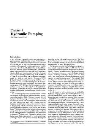
- 1. Chapter 6 Hydraulic Pumping Hal Petrie, National-Oilwell* Introduction A well will flow if it has sufficient reservoir potential ener- gy (pressure) to lift fluid to the surface. Artificial lift is applied to a well if the reservoir pressure is not sufficient to cause the well to flow, or when more production is desired in a flowing well. In either case, energy must be transmitted downhole and added to the produced fluid. Hydraulic pumping systems transmit power downhole by means of pressurized power fluid that flows in wellbore tubulars. Hydraulic transmission of power downhole can be accomplished with good efficiency. With 30”API oil at 2,500 psi in 27/,-in. tubing, 100 surface hhp can be trans- mitted to a depth of 8,000 ft with a flow rate of 2,353 B/D and with a frictional pressure drop of 188 psi. This pressure loss is 7.5 % of the applied power. If the trans- mission pressure is raised to 4,000 psi, the required flow rate drops to 1,47 1 B/D and the frictional pressure loss declines to only 88 psi. This is 2.2% of the applied sur- face power. Even higher efficiencies can be achieved with water as the hydraulic medium because of its lower vis- cosity . The downhole pump acts as a transformer to convert the energy of the power fluid to potential energy or pres- sure in the produced fluids. The most common form of hydraulic downhole pump consists of a set of coupled reciprocating pistons, one driven by the power fluid and the other pumping the well fluids. Another form of hydraulic downhole pump that has become more popular is the jet pump, which converts the pressurized power fluid to a high-velocity jet that mixes directly with the well fluids. ‘.2 In the turbulent mixing process, momentum and energy from the power fluid are added to the produced fluids. Rotatin hydraulic equipment has also been tested in oil wells. ‘,9 In this case, a hydraulic turbine driven by the power fluid rotates a shaft on which a multistage centrifugal or axial-flow pump is mounted. This type of ‘The origlnat chapter on this top% m the 1962 edltion was written by C J. Coberly and F Barton Brown. pump has not had widespread commercial use. The “free pump” feature, common to most designs, allows the pump to be circulated in and out of the well hydraulically without pulling tubing or using wircline services. The operating pressures used in hydraulic pumping sys- tems usually range from 2,000 to 4,000 psi. The most common pump used to generate this pressure on the sur- face is a triplex or quintiplex positive-displacement pump driven by an electric motor or a multicylinder gas or diesel engine. Multistage centrifugal pumps have also been used,5 and some systems have operated with the excess capacity in water-injection systems. ’ The hydraulic fluid usually comes from the well and can be produced oil or water. A fluid reservoir at the surface provides surge ca- pacity and is usually part of the cleaning system used to condition the well fluids for use as power fluid. Appro- priate control valves and piping complete the system. A schematic of a typical hydraulic pumping system is shown in Fig. 6.1. A wide variety of well conditions can be handled by hydraulic pumping systems. Successful applications have included setting depths ranging from 1,000 to 18,000 ft. ’ Production rates can vary from less than 100 to more than 10,000 B/D. Surface packages are available in sizes rang- ing from 30 to 625 hp. The systems are flexible because the downhole pumping rate can be regulated over a wide range with fluid controls on the surface. Chemicals to con- trol corrosion, paraffin, and emulsions can be injected downhole with the power fluid. Fresh water can also be injected to dissolve salt deposits. When pumping heavy crudes, the power fluid can serve as an effective diluent to reduce the viscosity of the produced fluids. The power fluid can also be heated for handling heavy crudes or low- pour-point crudes. Hydraulic pumping systems are suita- ble for wells with deviated or crooked holes that cause problems for conventional rod pumping. The surface fa- cilities have a low profile and can be clustered into a cen- tral battery to service numerous wells. This can be
- 2. 6-2 PETROLEUM ENGINEERING HANDBOOK A. Power-fluid tank B. Multiplexhigh-pressurepump C. Control manifold D. Wellhead controlvalve E. Downhole pump Fig. &i-Typical hydraulicpumping system mstallation advantageous in urban sites,offshore locations, and en- VirOnmentally sensitive areas. Jet pumps can be circulated around the 5-ft-radius loop of subsea through-flowline (TFL) installations8 joining gas-lift valves as the only ar- tificial lift devices suitable for these systems. Downhole Pumps Types of Installations The two basic types of installations are the fixed pump and the free pump designs. In the fixed installation, the downhole pump is attached to the end of a tubing string and run into the well, Free pump installations are designed to allow downhole pump circulation into and out of the well inside the power-fluid tubing string. The downhole pump can also be installed and retrieved by wireline op- erations. Fixed Pump Installations (Conventional Installations). In the fixed insert design, the pump lands on a seating- shoe set in tubing that has a larger ID than the OD of the pump. Power fluid is directed down the inner tubing string, and the produced fluid and the return power fluid flow to the surface inside the annulus between the two tubing strings, as shown in Fig. 6.2a. This system pro- vides a passage for venting free gas in the annular space between the outer tubing string and the inside of the well casing. To take full advantage of the gas venting passage, the pump should be set below the perforations. The power- Fig. 6.2-Downhole pump installations. fluid string is usually ?4, I, or I U in., depending on the size of the production tubing. This once-common system is now used mainly to fit a large-diameter downhole pump into restricted casing sizes and still retain the gas-vent fea- ture. It can also be used to lift one or both zones of a dual well with parallel strings. In the fixed casing design, the tubing, with the pump attached to its lower end, is seated on a packer, as shown in Fig. 6.2b. With this configuration. the power fluid is directed down the tubing string, and the mixed power fluid and the produced well fluids return to the surface in the tubing/casing annulus. Because the well fluids enter the pump from below the packer, all the free gas must be han- dled by the pump. This type of installation is normally
- 3. 6-3 HYDRAULIC PUMPING Pump-in When the handle is I” the down positron. high pressure power Huld Irom the multiplex power pump c~rculalesthelree hydraulic pump down the tubing to the bottom of the well The pow&flu~d begIns lo operate the pump once it’s seated at the standing valve Produced fluId and exhaust power fluld then return up the casing annulus through the valve and Into the flow Ilne. Pump-out With the selector handle in the up posItion, power fluld is drected down the casing annulus and returned up the tubing lifting the pump as the fluid flows back to the surface Bypass. bleed, and pump removal The power fluld bypass valve IS opened and the selector handle IS placed I” m!d-posItton This permits the well to be bled dawn and the pump to be removed and replaced. Fig. 6.3-Free-pump cycle. used in wells without much gas and with large-diameter, high-capacity pumps. If space permits, a gas-vent string can be run from below the packer to the surface. As with the fixed insert design, this installation is no longer com- mon, and both types have been largely supplanted by the various free pump installations. Note that in both of the fixed-type installations, the power fluid mixes with the produced fluids after passing through the pump. Free Pump Installations. The free pump feature is one of the most significant advantages of hydraulic pumping systems. Free pump installations permit circulating the pump to bottom, producing the well, and circulating the pump back to the surface for repair or size change. Free pump installations require that a bottomhole assembly (BHA) be run in on the tubing string. The BHA consists of a acating shoe and one or more seal bores above it and scrvcs as a receptacle for the pump itself. BHA’s are of robust construction and USCcorrosion-resistant sealing bores to ensure a long life in the downhole environment. Once run in on the tubing string. they normally remain in place for years, even though the downhole pump may be circulated in and out numerous times for repair or resiz- ing. As shown in Fig. 6.3, a wireline-retrievable stand- ing valve ib landed in the seating shoe below the pump. The pump is run in the hole by placing it in the power- fluid tubing string and circulating power fluid in the nor- mal direction. When the pump reaches bottom, it enters the seal bores. begins stroking. and opens the standing valve. During normal pumping, this valve is always held open by well fluids drawn into the pump suction. During pump-out, the normal flow of fluids is reversed at the sur- face with appr.opriate valving, and pressure is applied to the discharge flow path of the pump. This reversal of flow closes the standing valve and permits the pump to be cir- culated to the surface. Circulating the pump out normal- ly takes from 30 minutes to 2 hours. depending on the well depth and the circulating flow rate. The benefits of being able to circulate the downhole pump in and out of the well include reduced downtime and the ability to operate without a pulling unit for tubing. cable, or rod removal. Another significant advantage is that pressure and temperature recorders can be mounted on the pump to monitor downhole conditions with differ- ent pumping rates. At the conclusion of the test, circulat- ing the pump to the surface also retrieves the recorder. Leakage of tubing pressure can be checked by substitut- ing a dummy pump for the normal production unit. Steam- ing, acidizing, or other chemical treatment of the formation can be done if the pump is circulated out and the standing valve is wirelined out. A flow-through blank- ing tool may be run instead of the pump for such treat- ments if isolation of the power fluid and discharge flow paths is desired. The casing free installation, shown in Fig. 6.2~. is at- tractive from an initial-cost standpoint because it uses only one string of tubing. At first glance it seems to be the same as the fixed casing design. The crucial difference is that, instead of being attached to the end of the power-fluid string, the pump fits inside it to allow circulation into and
- 4. 6-4 PETROLEUM ENGINEERING HANDBOOK Fig. 6.4-Free-pump, parallel, closed-power BHA. out of the well. For a given-diameter pump, this requires a larger-diameter power-fluid string, which reduces the annular flow path for the discharge fluids. In most cases, more than adequate flow area remains. Tubing as small as I % in. can be run in systems with 2%.in. tubing used as casing. In 1‘/z-in. tubing, only jet pumps can be used. In 2%.in. or larger tubing, either jet or reciprocating pumps can be used. Usually, 26-m. power-fluid tubing is used in 4-in. or larger casing, 2x-m. tubing in 5 %-in. or larger casing, and 3%-in. tubing in 6X-in. casing or larger. Only a very few free-pump installations have been made for 41/2-in. or larger tubing strings. Because the BHA sits on a packer, the pump must handle all the gas from the well in addition to the liquids. A gas-vent string can be run to below the packer if gas interference limits pump performance. Such an installation ISshown rn big. 6.2d. In both the vented and unvented systems, the pow- er fluid mixes with the produced fluids and returns to the surface. In wells where the produced fluids should be kept off the casing wall or where gas venting is desired, the parallel free installation should be considered. This installation, which requires two parallel tubing strings, normally does not require a packer. As shown in Fig. 6.2e, the BHA is suspended on the power-fluid tubing string, and the return string is either screwed into the BHA or is run separately with a landing spear that enters a bowl above the BHA. The tubing/casing annulus serves as a gas-vent passage. and to take full advantage of this, the unit should be set below the perforations. If the well is not pumped off fully, well fluids will rise above the BHA until the bottomhole pressure (BHP, pump-suction pressure) increases to the point that the well inflow rate and BHP match the inflow performance rela- tionship (IPR) curve of the well. This will expose some of the casing above the perforations to well fluids. In some cases, this may be desirable to prevent collapse of the casing, but in corrosive wells, such as those encountered in CO2 flooding or with H2.S present, it may be undesira- ble. In such a case, a packer may be set above the perfo- rations, although the gas-vent feature is then lost unless another gas-vent string is run to below the packer. The size of the downhole pump dictates the power-tluid tubing size, and the casing size dictates how large the parallel return string can be. When the return string is limited in size, fluid friction may restrict the obtainable production or the practical setting depth. Closed Power-Fluid Systems All the installations discussed so far are open power-fluid types. This means that the power fluid and the produced fluid are mixed together after leaving the downhole pump and return to the surface together in a common flow pas- sage. Jet pumps are inherently open power-fluid pumps because the energy transfer depends on mixing the power fluid and produced fluid. Reciprocating pumps. however, keep the power and produced fluids separate during the energy transfer process because there is a separate piston (or piston face) for each fluid. If the BHA has appropri- ate seal bores and passages to keep the two tluids sepa- rated, the power fluid can be returned to the surface in a separate tubing string. The extra tubing string for the power-fluid return classifies these installations in the
- 5. HYDRAULIC PUMPING parallel free category. An example of a c,lo.r~dpo,l,~~~~~~;~~ instufhtion is shown in Fig. 6.4. The principal advan- tage of closed power-fluid installations is that only the pro- duced fluids need to go through the surface separating facilities. and the power fluid remains in a separate, closed loop. The resulting smaller surface facilities may be de- sirable in certain areas, such as townsite leases and off- shore installations. In principle, the power-fluid clean- liness can be maintained better because it is not contami- nated with well fluids. When water is used as the power fluid, it is generally necessary to add small amounts of corrosion inhibitors and lubricants. These would be lost in the open system, but arc retained in the closed system. Offsetting the advantages of the closed system are ti e higher initial cost of the extra tubing string and more com- plex pump and BHA. Most closed power-fluid installa- tions are found in the urban and offshore wells of California. Reverse Flow Systems Two considerations-the need to keep produced fluid off the casing and to minimize fluid-friction losses-have led to the use of reverse-flow installations (also known as reverse-circulation installations) in some wells. A reverse- flow casing installation is shown in Fig. 6.5. These sys- tems are most commonly used with jet pumps, although a few installations have been made with reciprocating pumps. The casing system uses the tubing/casing annulus for power fluid, and the tubing string, which contains the pump, is used for the combined power fluid and produc- tion. This protects the casing with inhibited power fluid and is most useful when severe corrosion is anticipated. It does require the use of a heavier wall casing to avoid bursting it when power-fluid pressure is applied. The parallel system uses the smaller-size string for power fluid and the larger main string that contains the pump for the combined power fluid and production. The primary ad- vantages of this system are reduced friction, gas venting, and protection of the casing. As discussed in the section on the parallel free design. complete casing isolation re- quires a packer below the BHA. Both types of reverse- flow installations may require a latch or friction holddown to position the pump in the BHA during startup or to re- tain it in position during pumping, depending on the bal- ance of forces on the downhole pump. In reverse-flow installations. the pump is wirelined often in and out of the well, but a modified form of the free pump feature can be used. With jet pumps, the pump is run in with a pusher-type locomotive, which then circu- lates to the surface during pumping. To retrieve the pump, a similar blanked-off locomotive with a fishing tool at- tached is circulated down and latched to the pump. When flow is established in the normal pumping mode direc- tion, the pump will surface. This sequence of operations is shown in Fig. 6.6. Fig. 6.7 shows a reverse-flow in- stallation with a reciprocating pump. Because the engine and pump valving in these pumps does not permit flow- back to the pump suction for unseating the pump, a BHA side line must be run to the bottom of the pump. The latch assembly on top of the pump keeps it on seat during nor- mal pumping. To retrieve the pump, a releasing tool is dropped or wirelined before the pump is circulated to the surface. Once the latch is released, the flow of fluid in the normal pumping mode will surface the pump. r Power Discharge 6-5 fluid -Lock A upper seal ~51 iding sleeve body *SI iding sleeve -Jet pump -Lower sea I Suet ion tI Fig. 6.5~-Reverse-flowjet-pump casing type in sliding sleeve.
- 6. PETROLEUM ENGINEERING HANDBOOK (1)Pump In. (2)Seat Pump. (4)Retrievewith reversed flow and fishinglocomotive. (5)Pump Out. (6)Bypass, bleed,and pump removal. (3)Operate-pusher locomotive surfaces and standing valve opens. Fig. &B--Reverse-flow, free-pump cycle. TFL Installations TFL installations have been developed for offshore loca- tions to allow circulation of various downhole tools to the bottom of remote wells from a central platform. A typical installation is shown in Fig. 6.8. Because a Sft-radius loop is an integral part of the subsea wellhead installa- tion, the size of the tools that can be circulated through it is limited. Of the various artificial-lift tools, only gas- lift valves and hydraulic jet pumps are sufficiently corn- pact to be compatible with the system. When jet pumps are used, they may be normal-flow or reverse-flow types. Fig. 6.9 is an example of the reverse-flow installation used with TFL. The normal-flow installation is the simplest because it is essentially a parallel free installation and does not require special latches or holddowns. However, the pump has more complex internal fluid passages and the discharge fluid passes through the crossover port of the downhole H-member, which serves as a BHA. Because of the potential for erosion and corrosion of the crossover member, many operators prefer the reverse-flow instal- lation shown in Fig. 6.9. Here, only the power fluid passes through the crossover port, and the pump flow passages are of a simpler design and can have a higher capacity. Note the compactness of the pump and the use of univer- sal joints that allow flexibility between the pump and the lower seal section. Circulating the pump in and out. how- ever, is more complex, and the procedures described for non-TFL reverse-flow installations must be used. The dual-sleeve side-door choke is probably the most important item in the string other than the pump itself when TFL operations are performed. This item is run open as shown to allow bypass past the pump for circulat- ing tools into and out of the hole because not much fluid can be circulated through the pump nozzle. Once pump operations are ready to begin, the sleeve is closed by pres- suring both strings. When pulling the pump, the sleeve is reopened by pressuring the tubing string that the pump is landed in, and circulation is then re-established.
- 7. HYDRAULIC PUMPING Dual Wells. Hydraulic pumps lend themselves to the com- plex problem of the production of two separate zones in a single wellbore. When the two zones have different reservoir pressures. it is not practical to allow communi- cation between them because the higher-pressure zone will flow into the lower-pressure zone. To meet the artificial lift requirements of the two distinct zones, two downhole pumps are usually required. It would be highly unusual if the same power-tluid pressure and rate were required for each zone; consequently, a separate power-fluid line for each pump is usually required. A number of plumbing configurations are possible. One option is shown in Fig. 6.10. The two pumps are physically connected and are run in and retrieved as a unit. In some cases, dual zones have been produced separately by use of double pump ends with a common engine. Tandem Pumps. When the well capacity requirements exceed what can be produced by a single pump, it is pas- sible to install two pumps in parallel or tandem to double the displacement of the downhole equipment. Again, the pumps are physically connected to form a single unit, but each pump is free to run independently. Historically, tandem pump installations have used reciprocating pumps. The downhole arrangement is simi- lar to that of Fig. 6.10, but without the passages that route fluid from two separate zones. It is possible to use jet pumps in the same manner, but this is rarely done be- cause it is usually possible to get sufficient capacity in a single jet pump. Since the introduction of jet pumps about 1970, high-volume hydraulically pumped wells have generally used jet pumps instead of tandem reciprocating pumps. 6-7 Fig. 6.7~-Reverse-flowtubing arrangement (stroking pump). Lubr i cator Manifold and instrumen Pressure transducers Entry loops Subsea we I lhead Circulation point (H-member 1 Jet pump location tat ion Fig. 6.6-Typical offshoreTFL installation.
- 8. 6-8 PETROLEUM ENGINEERING HANDBOOK Production Latch Seals Side door choke Universal joint Diffuser Throat Nozzle Power fluid I 1' 1 ;i + Suction Production discharge Pump - plunger Pump - discharge valve Pump - barrel - Pump intake valve Fig. 6.9--Reverse-flowTFL jetpump. Fig. 6.10-Dual-zone installation with two free pumps operatingintandem, gas from upper zone produced through casing. Fig. 6.11--Single-acting pump end Principles of Operation- Reciprocating Pumps The pump end of a hydraulic downhole pump is similar to a sucker-rod pump because it uses a rod-actuated plung- er (also called the pump piston) and two or more check valves. The pump can be either single-acting or double- acting. A single-acting pump follows rod-pump design practices closely and is called single-acting because it dis- places fluid to the surface on either the upstroke or down- stroke (but not on both). An example is shown schematically in Fig. 6.11. Fig. 6.12 shows a double- acting pump that has suction and discharge valves for both sides of the pump plunger. which enables it to displace fluidsto the surface on both the upstroke and downstroke. With either system, motion of the plunger away from a suction valve lowers the pressure that holds the valve closed, it opens as the pressure drops, and well fluids are allowed to enter the barrel or cylinder. At the end of the stroke, the plunger motion reverses, which forces the suc- tion valve to close and opens the discharge valving. In a sucker-rod installation. the rod that actuates the pump plunger extends to the surface of the well and con- nects to the pumping unit. In hydraulic pumps. however, the rod is quite short and extends only to the engine piston. The engine piston is constructed similarly to the pump plunger and is exposed to the power-fluid supply, which
- 9. PETROLEUM ENGINEERING HANDBOOK -Engine piston -Engine valve -Engine cylinder -Power fluid in rPower fluid exhaust i and production discharge -Pump plunger -Pump d ischarge va Ive -Pump barre I -Pump intake valve Type F FEB, FE Fig. 6.14--Single-acting downhole unit nears the ends of the upstroke and downstroke. Combi- nations of mechanical and hydraulic shifting are possi- ble. The engine valve may be located above the rod-and- plunger system, in the middle of the pump, or in the en- gine piston. Note that the two designs illustrated and discussed do not exhaust the design possibilities offered by the vari- ous pump manufacturers. Examples of combinations of these and other design concepts can be seen in the cross- section schematics of the various pump types that accom- pany the pump specifications in Tables 6. I through 6.4 and Figs. 6.15 through 6.18. Common to all the designs, however. is the concept of a reversing valve that causes an engine piston (or pistons) to reciprocate back and forth. This strokes the pump plunger (or plungers) that lifts fluid from the well. Because the engine and pump are closely coupled into one unit, the stroke length can be controlled accurately. With a precise stroke length, the unswept area or clear- ance volume at each end of the stroke can be kept very small, leading to high compression ratios. This is very Type VFR Type V Type 220 Fig.6.15-Manufacturer “A” pump types forTable 6.1 important in maintaining high volumetric efficiency when gas is present and generally prevents gas locking in hydraulic pumps. The engine valves and their switching mechanisms usually include controls to provide a smooth reversal and to limit the plunger speed under unloaded conditions. The unloaded plunger speed control is often called governing and minimizes fluid pound when the pump is not fully loaded with liquid. In this way, shock loads in the pump and water hammer in the tubing strings are softened, which reduces stresses and increases life. Pressures and Forces in Reciprocating Pumps Reciprocating hydraulic pumps are hydrostatic devices. This means that the operation of the unit depends on pres- sures acting against piston faces to generate forces. and that the fluid velocities are low enough that dynamic ef- fects can be neglected. A pressurized fluid exerts a force against the walls of its container. This force is perpen- dicular to the walls regardless of their orientation. If the pressurized container consists of a cylinder with one end blanked off and the other end fitted with a movable plung-
- 10. HYDRAULIC PUMPING 6-11 TABLE 6.1~-RECIPROCATING PUMP SPECIFICATIONS. MANUFACTURER “A” Puma Type F, Fe, FEB 23/8-in. tubing F201311 F201313 F201611 F201613 FE8201613 FE6201616 27/g-h. tubing F251611 F251613 F251616 FE252011 FE252013 FE252016 Type VFR 23/8-h. tubing VFR201611 VFR201613 VFR201616 VFR20161613 VFR20161616 27/8-h. tubing VFR252015 VFR252017 VFR252020 VFR25202015 VFR25202017 VFR25202020 Type V 27/-/n. tubing V-25-11-1 i-8 V-25-11-095 V-25-11-076 V-25-11-061 V-25-21-075 V-25-21-063 V-25-21-050 V-25-21-041 Type 220 23/-h. tubing 330-201610 330-201612 530-201615 27/-h. tubing 348-252012 348-252015 548-252017 548-252019 536-252020 Note Pump Size F. FE, FEB. VFR Types F Disolacement B/D oer strokeslmin Puma 3.0 4.2 4.2 4.2 3.0 6.4 4.2 6.4 6.2 9.4 9.4 9.4 3.3 7.0 4.6 7.0 7.0 7.0 5.0 16.5 7.0 16.5 10.6 16.5 2.12 4.24 2.96 4.24 4.49 4.24 2.96 6.86 4.49 6.86 5.25 8.89 7.15 8.89 9.33 8.89 5.25 15.16 7.15 15.16 9.33 15.16 6.31 5.33 6.31 6.66 3.93 5.33 3.93 6.66 6.31 8.38 6.31 10.00 3.93 8.38 3.93 10.00 4.22 8.94 5.46 8.94 7.86 8.94 8.73 22.35 12.57 22.35 17.11 22.35 20.17 22.35 25.18 25.18 V Types v 220 Sertes 3 Number of seals 20 Nommal tubing (2 I” ) 25 Nommal tubmg (2% I” ) 48 Stroke length p, 13 Engme (1 3 I” ) 11 Single engme (double = 21) 25 Nomlnal tubing (2% in.] XX Second engine (VFR only) 118PIE 20 Engine (2 000 IO.) 11 Pump (1 1 in ) 12 Pump (1 200 m.) Types F. FE. FEB are slngle-seal, internal-portmg; 220, VFR, and V are multiple-seal, external-pomng. Engine Rated Speed (B/D) Enaine Total PIE Puma 204 285 204 285 340 517 214 299 455 255 357 540 318 444 673 444 673 630 8.58 1,119 630 858 1,119 1,229 1,299 550 550 1,173 1,072 550 550 422 546 786 629 905 1,232 1,452 2,014 286 490 0.71 286 571 1.00 435 639 0.47 435 720 0.66 517 857 0.66 517 1,034 1.00 455 669 0.47 455 754 0.66 455 910 1.00 842 1,097 0.30 842 1,199 0.42 842 1.382 0.64 636 954 0.62 636 1,080 0.87 636 1,309 1.32 1,029 1,473 0.54 1,029 1,702 0.81 1,067 1,697 0.74 1,067 1,925 1.00 1,067 2,186 1.32 1,819 2,449 0.41 1,819 2,677 0.56 1,819 2,938 0.73 1,098 2,397 1.18 1,372 2,671 0.96 746 1,296 0.76 932 1,482 0.61 1,559 2,732 0.75 I;700 23772 0.63 1,173 1,723 0.50 1,400 1,950 0.41 894 1,316 0.49 894 1,440 0.63 894 1.680 0.89 1,609 2,238 0.40 1.609 2.514 0.57 11609 2,841 0.78 1,609 3,061 0.93 2,014 4,028 1.00 Maximum Rated Speed (strokes/min) 68 68 68 68 ii; 65 65 65 51 51 51 150 150 150 150 150 120 120 120 120 120 120 206 206 140 140 186 170 140 140 100 100 100 72 72 72 72 80
- 11. 6-12 PETROLEUM ENGINEERING HANDBOOK TABLE 6.2--RECIPROCATING PUMP SPECIFICATIONS, MANUFACTURER “B“ Pump Type A 23/8-in. tubing 2x l-13/16 2x1-1 2x l-1$& 2x 13/16-l 2x 1%6-l% 2x13/16-1x1 2x13/16-13/16x1 2x 1%6-1%6x1%6 2x-in. tubing 2% x 1x-1 2% x IV-l'/8 2'/2 x IX-1% 2% x l'h-l'/,Fj 2% x l%e-1% 2% x 15/8-l% 2% x 15/s-15/8 2% x 1%6-l% x 1% 2% x 1%,-l%, x 1% 2% x i&-l'/,6x 1'/,6 2'/2 x 15/E-15/8x 15/s 3Yz-in. tubing 3x 1%-l% 3x l'h-lJ/B 3 x 1%1% 3x 1'/2-1% 3 x 13/4-i% 3x 1%-l% 3 x 13/i-IV4 x 1% 3 x 13/4-l%x 1% 3x 13/i-13/9x 1% 3X 1%.-l% x 1% 4Win. tubing 4x2-1% 4x2-2 4X2-23/8 4X23/8-2 4 x23/0-23/s 4X2%-2X 1% 4x2$&2x2 4 X23/-23/n x 2 4 x 23&23/g x 23/ We B 23/s-h. tubing 2x 13/s-13/16 2x 13/s-13/s 2X13/-13/j~Xl3/,,6 2 x 13/a-13/8 x 1y,#j 2~13/g-i3/~13/g Notes Displacement B/D per strokes/min Rated Speed (B/D) Pump Engine Pump Engine Total PIE -~__~ Maxlmum Rated Speed (strokeslmln) 1.15 2.15 139 2.10 2.15 255 3.25 2.15 393 2.10 3.30 255 3.25 3.30 393 4.20 3.30 508 5.35 3.30 647 6.50 3.30 787 260 399 0.545 260 515 1.000 260 653 1.546 399 654 0.647 399 792 1.000 399 907 1.290 399 1,046 1.647 399 1,186 2.000 121 121 121 121 121 121 121 121 2.56 5.02 256 502 758 0.520 3.67 5.02 367 502 868 0.746 4.92 5.02 492 502 994 1.000 7.03 5.02 703 502 1,205 1.431 4.92 7.13 492 713 1,205 0.700 7.03 7.13 703 713 1,416 1.000 7.03 9.27 703 927 1,630 0.770 7.45 9.27 745 927 1,672 0.820 9.09 9.27 909 927 1,836 1.000 9.84 7.13 984 713 1,697 1.400 11.95 7.13 1,195 713 1,908 1.701 14.06 7.13 1,406 713 2,119 2.000 18.18 9.27 1.818 927 2,745 2.000 100 100 100 100 100 100 100 100 100 100 100 100 100 5.59 9.61 486 7.43 9.61 646 9.44 9.61 821 14.00 9.61 1,218 9.44 14.17 821 14.00 14.17 1,218 11.18 14.17 973 18.18 14.17 1,642 23.44 14.17 2,093 28.00 14.17 2,436 836 1,322 0.592 836 1,482 0.787 836 1,657 1.000 836 2,054 1.480 1,233 2,054 0.676 1,233 2,451 1.000 1,233 2,206 0.800 1,233 2,875 1.351 1,233 3,326 1.675 1,233 3,669 2.000 87 87 87 87 87 87 87 87 87 87 14.40 21.44 1,109 21.00 21.44 1,617 32.50 21.44 2,503 21.00 32.94 1,617 32.60 32.94 2,503 35.40 32.94 2,726 42.00 32.94 3,234 53.50 32.94 4,120 65.00 32.94 5,005 1,651 2,760 0.687 1,651 3,268 1.000 1,651 4,154 1.541 2,536 4,153 0.649 2,536 5,039 1.000 2,538 5,262 1.094 2,536 5,770 1.299 2,536 6,656 1.650 2,536 7,541 2.000 77 77 77 77 77 77 77 77 77 3.15 4.54 381 549 930 0700 121 4.50 4.54 544 549 1,093 1.000 121 6.21 4.54 751 549 1,300 1.380 121 7.55 4.54 913 549 1,463 1.680 121 8.90 4.54 1,076 549 1,625 1.980 121 1 Pump sue nominalx engine-pumpx pump (in.). 2 Illustrations for smgle-pump end. double available onA.S,and0. 3. Types- All double-aclmg. A Smgleseal, internal poning B Multiple seal, external porting D Muliple seal, external porting, double engine E MuWe seal. external porting, opposed pistons with central engine
- 12. HYDRAULIC PUMPING 6-13 TABLE 6.2~-RECIPROCATING PUMP SPECIFICATIONS, MANUFACTURER “8" (continued) Pump Type 0 27/,-h. tubing 2% x l%-1% 2% x 1%1% 2% x 13/4-1'/2 x 1% 2% x 1%1% x l'h 2% x 1%-1%x 1% 3%-h tubing 3 x21/g-17/ 3 x 21/8-21/s 3x2'/,-1',f0xX17/8 3x21/8-21/8x17/ 3x 21/8-21/,x 2'/, Type D 23/8-in. tubing 2 x 13/,6X 13/&i% 2x13/16x13/s-13/ 2x13/,~xl3/~-13/,~xl3/,~ 2 x 13&jx 13/s-13/8 x 1% 2x13/l~x13/8-13/8x13/8 27/-in. tubing 2% x 17/,6X l%-1% 2% x 1%6 x 1%-l % 2'/2xl~,~x13/4-1'/2x1'/2 2%x1~,~x13/4-13/qx1% 2%x17/,~x13hx13/4 3Win. tubing 3 x 1% x 21/,-l% 3x 1% x 2'/*-2'/8 3xl3/4x2'/~-17/8x17/~ 3Xl%X2'/&2'/8X17/ 3 x 1% x 2'/8-2'/8 x 2'/8 Type E 23/,-in. tubing 2x13/8 27/8-in. tubing 2% x 1% 3%In. tubing 3x21/8 BID per strokes/min Enqine Pump A Pump Engine Total PIE 7.44 10.96 10.86 10.96 14.52 10.96 17.94 10.96 21.36 10.96 15.96 21.75 21.55 21.75 31.34 21.75 36.94 21.75 42.53 21.75 3.15 7.79 4.50 7.79 6.21 7.79 7.55 7.79 8.90 7.79 7.44 17.99 1086 17.99 14.52 17.99 1794 17.99 21.36 17.99 15.96 35.74 21.55 35.74 31.34 35.74 36.94 35.74 42.53 35.74 20.27 17.59 40.63 35.45 71.70 62.77 1 Pump sue nomlnalrenglne-pumpxpump (in ) 2 Itiustrat~onsfor Sinale~DumD end, double wallable on A, 8. and D Displacement Rated Speed (BID) 744 1,086 1,452 1,794 2,136 100 100 100 100 100 1,388 1,875 2,726 3,214 3,700 1,096 1,840 0.685 1,096 2,182 1.000 1,096 2,548 1.336 1,096 2,890 1.652 1,096 3,232 1.957 1,892 3,280 0.740 1,892 3,787 1.000 1,892 4,618 1.454 1,892 5,106 1.714 1,892 5,592 1.974 87 87 87 87 87 381 943 1,324 0.407 121 544 943 1,487 0.581 121 751 943 1,694 0.802 121 914 943 1,857 0.976 121 1,076 943 2,019 1.150 121 744 1,086 1,452 1,794 2,136 1,799 2,543 0.411 1,799 2,885 0.608 1,799 3,251 0.813 1,799 3,593 0.976 1,799 3,935 1.196 3,109 4,497 0.449 3,109 4,983 0.606 3,109 5,835 0.882 3,109 6,322 1.039 3,109 6,809 1.197 100 100 100 100 100 1,388 1,874 2,726 3,213 3,700 87 87 87 87 87 1,317 1,143 2,454 1.152 2,092 4,491 1.146 3,515 7,522 1.142 65 2,400 59 4,007 56 Maximum Rated Speed (strokes/min) 3. Types All double-&g A Sinale seal, internal portina B Muliple seal, exlernil p&g D. Mulbple seal, ewlernal porting, double engme. E Mulbpte seal. external pottmg. opposed pistons with central engine
- 13. 6-14 PETROLEUM ENGINEERING HANDBOOK Type “A” Type “6” Type “D” Fig. 6.16-Manufacturer “B” pump types forTable 6.2 er, as shown in Fig. 6.19, a force will have to be applied W=FL, .,,...,...........................(2) to the plunger to resist the force exerted by the pressur- ized fluid. A force of 1,000 lbf will be required to re- strain a plunger whose cross-sectional area is 1 sq in. if where W=work, in.-lbf, and L=distance, in. the pressure in the cylinder is 1,000 psi. If the plunger moves 12 in., it will do 12,000 in.-lbf of work (or 1,000 ft-lbf of work). Because the plunger F=pA, . . . . . . . . . . . . . . . . . . . . . . . . . . . . . . . . ...(I) is moving at 1 in./sec. it will take 12 seconds to com- plete its travel. Power is defined as the rate of doing work. where F = force, Ibf, P=Wit, . . . . . . . . . . . . . . . . . . . . . . . . . . . . . p = pressure, psi, and where A = area, sq in. P = power, ft-lbfisec, This is the condition of static equilibrium for the plunger t = time, seconds, and when all forces balance and no movement is taking place. W = work, ft-lbf. Suppose next that a supply line is connected to the blanked-off end of the cylinder, as shown in Fig. 6.20, In this example, the power is 1,000 ft-lbf of work in and that a pump supplies fluid at a rate of 1 cu in.isec 12 seconds, or 83.3 ft-lbf/sec. Horsepower is defined as while maintaining the pressure at 1,000 psi. This will 550 ft-lbf/sec (or 6,600 in.-lbf/sec), which means that the cause the plunger to move in the cylinder at the constant horsepower of this system can be represented as speed of I’in./sec against the 1,OO&lbf restraining force. In this condition of dynamic equilibrium. work can be done by the system because work is defined as force times Ph’&, . . . . . . . . . . . . . . . . . . . . . . . . . . . . . ...(4) distance. where Ph =horsepower, hp.
- 14. HYDRAULIC PUMPING 6-15 TABLE 6.3~RECIPROCATING PUMP SPECIFICATIONS, MANUFACTURER “C” Puma PowerliftI 23/&in. tubing 2 x 15/B X 1'/,6 2X15/X1'/4 2 x 15/8 X 1% 2X15/8X15/8 2%-in. tubing 2%X2X1% 2'/2X2Xl'h 2%X2X15/& 2%X2X13/4 2%X2X2 2% x 15/e x l'/,fj 2'/2 x 15/gx1'/4 2’/2 x 15/8x1% 2% x 15/gx15/8 21/2x IS/*xI'/,6 2% x 15/e x 1% 2% x IS/,x1% 2% x 15/gx15/s 31/z-in. iubing 3 x 2'h x 2% 3 x 2% x 2% 3x2%x2 3x2'/zxl% PowerliftII 23/8-in. tubing 2X1%6 2 x 1% 2x 1% 27/8-in. tubing 2% x 1% 2’i2 x I'/4 2% x 1'h Disolacement B/D oer strokeslmin Pump 6.45 15.08 225 528 753 0.52 35 8.92 15.08 312 528 840 0.72 35 11.96 14.03 478 561 1,039 1.16 40 14.03 14.03 561 561 1,122 1.36 40 12.02 17.30 20.30 23.60 30.80 6.45 8.92 12.85 15.08 8.69 12.02 17.03 20.30 43.71 43.71 1,311 1,311 2,622 1.21 30 35.41 43.71 1,062 1,311 2,373 0.98 30 27.98 43.71 840 1,311 2,151 0.77 30 21.42 43.71 643 1,311 1,954 0.59 30 5.53 12.10 597 1,307 1,904 0.524 108 7.65 12.10 826 1,307 2,133 0.725 108 30.00 26.35 1,560 1,370 2.930 1.147 52 12.59 17.69 1,322 1,857 3,179 0.725 105 8.74 17.69 918 1,857 2,775 0.503 105 50.00 43.97 2,500 2,199 4,699 1.146 50 Engine Rated Speed (B/D) Pumo Enaine Total PIE 30.80 264 30.80 467 30.80 547 30.80 826 30.80 1,078 15.08 225 15.08 312 15.08 450 15.08 528 20.30 234 20.30 325 20.30 467 20.30 547 678 942 0.44 832 1,299 0.68 832 1,379 0.80 1,078 1,904 1.06 1,078 2,156 1.38 528 753 0.52 528 840 0.72 528 978 1.03 528 1,056 1.21 548 782 0.52 548 873 0.72 548 1,015 1.03 548 1.095 1.21 Maximum Rated Speed (strokes/min) 22 27 27 35 35 35 35 35 35 27 27 27 27 In our example, 83.3 ft-lbf/sec corresponds to 0.15 hp. If we were to supply the pressurized fluid at 2 cu in./sec, the plunger would move the 12 in. in 6 seconds. The work done would be the same, but because it would be done in half the time. the hp would be twice as great. Note that we have interpreted the hp in terms of the work done through the plunger per unit time. This power is supplied by the pump pressurizing the fluid. The plunger transforms the fluid power to mechanical. This is the ac- tion of a hydraulic motor. The hydraulic equivalent of 0. I5 hp is a flow rate of 1 cu in./sec at 1,000 psi. If the flow rate in cubic inches per second is multiplied by the pres- sure in pounds force per square inch, the product will have units of inch-pounds per second, which are the dimen- sions of power. Conversion of units will show that 1 cu in./sec is the same as 8.905 B/D. If 8.905 B/D at 1,000 psi is 0. IS hp. it follows that P,,=yxpx0.000017; (5) where q=flow rate, B/D, and p-pressure, psi. Eq. 5 shows that the same power can be obtained with high flow rates at low pressure, or with lower flow rates at a higher pressure. This is a very useful feature of hydraulic power transmission. Only the flow rate and the pressure enter into this relationship; the density, or spe- cific gravity, of the fluid does not. The process described can be reversed. A force of 1,000 lbf applied to the plunger in Fig. 6.20 can force fluid out of the line at a pressure of 1,000 psi. In this case, the mechanical power of the plunger would be transformed into fluid power as it is done in pumps. A useful consequence of the relationship expressed in Eq. 1 is demonstrated in Fig. 6.21. Two plungers of different diameters are connected together by a rod. The section of the assembly occupied by the connecting rod is vented to the atmosphere. The face area of the larger plunger is 2 sq in. and the face of the smaller plunger is I sq in. Fluid at l,OOO-psi pressure is supplied to the cylinder that contains the larger plunger. This causes the plunger to push through the rod and against the smaller plunger with a force of 2,000 lbf. To restrain the motion of the rod-and-plunger system, an opposing force of 2,000
- 15. 6-16 PETROLEUM ENGINEERING HANDBOOK TABLE 6.4--RECIPROCATING PUMP SPECIFICATIONS, MANUFACTURER “D” Displacement BIDper strokes/min Rated Speed (B/D) Maximum Rated SDeed Total PIE (strokeslmin) Engine Pump Engine Pump Pump 900 Series 23/-in. tubing 2x 1% 2x 1%6 2 x 1% 2 x l'h 3.5 6.65 95 180 275 0.66 27 7.0 13.30 189 359 548 0.66 27 9.6 13.30 259 359 618 0.93 27 13.8 13.30 372 359 731 1.33 27 2y8-in.tubing 2'/2 x l’h6 2% x 1'/j6 2% x 1% 2x! x 1'/2 2'/2 x 1% 2% x 2 3.5 10.6 95 266 381 0.43 27 7.0 21.2 189 572 761 0.43 27 9.5 21.2 256 572 828 0.58 27 13.7 21.2 370 572 942 0.83 27 18.6 21.2 502 572 1,074 1.13 27 24.2 21.2 654 572 1,226 1.47 27 3Win. tubing 3 x 1% 3x1% 3x2 3 x 2% 3 x 2% 4Win. tubing 4x2s 4~2% 4 x3% 924 Series 2%~in. tubing 7045-92-4210 7065-92-4210 7100-92-4210 15.5 36.1 419 975 1,394 0.53 27 36.1 570 975 1,545 0.72 27 36.1 743 975 1,718 0.94 27 36.1 940 975 1,915 1.20 27 36.1 1,160 975 2,135 1.47 27 21.1 27.5 34.8 43.0 34.8 63.5 940 1.715 2,655 0.68 27 52.0 63.5 1,404 1,715 3,119 1.01 27 72.6 63.5 1,960 1,715 3,675 1.41 27 4.7 7.25 287 442 729 0.65 61 9.4 14.5 574 885 1,459 0.65 61 14.5 14.5 885 885 1,770 1.00 61 Notes Pump SIX 900 Sews-nominal x pump plunger diameter Types 900-Smgle-seal, single-aclmg. Internal-portmg. 924-Single-seal. dO”bbact,ng, Internal-parling. Ibf must be applied to the smaller plunger. This can be accomplished with fluid in the smaller cylinder at 2.000 psi, If these pressures are maintained and fluid is sup- plied to the larger cylinder at a constant rate, the rod-and- plunger system will move to the right at a constant rate. Fluid will be forced out of the smaller cylinder at half the rate it is supplied to the larger cylinder, but with twice the pressure. This hydraulic transformer process is rever- siblc. which would entail supplying 2,(M)-psi fluid to the smaller cylinder to make I.OOO-psifluid flow out of the larger cylinder at twice the tlow rate supplied to the smaller cylinder. In either case, the input and output horsepowers are the same because no losses have been considered. The characteristics of such a rod-and-plunger system can be used to advantage in hydraulic pumps. In shallow wells where the pressure requirements of the pump arc low. a large pump plunger can be used in conjunction with a small engine piston without requiring cxccssivcly high prcsaurcs to be supplied to the engine. In deeper wells, where the discharge pressure of the pump will be high, a small pump plunger is used in conjunction with a large engine piston to reduce the power-fluid pressure require- ment. The smaller pump plunger will, howev,cr. produce less fluid at the same stroking rate than the larger pump plunger. Hydraulic pump manufacturers otter a variety of engine and pump combinations to meet the require- ments of different flow rates and depth settings (see ex- amples in Tables 6.1 through 6.4). Pressures and Force Balance in Downhole Pumps By looking at the pressures and forces in a downhole hydraulic pump, a generalized equation can be developed to predict the operating pressure required in a particular well. Two pumps are analyzed to show the generality of the solution. Fig. 6.22 shows a double-acting pump with the various areas identified and the pressures labeled for upstroke and downstroke conditions. In this design. both the upper and lower rods are exposed to the power-fluid pressure, pi,/. At the beginning and end of each half- stroke, brief periods of decclcration and acceleration occur, but the majority of the stroke is at constant veloci- ty. For the constant-velocity condition. the sum of the forces acting downward must equal the sum of the forces acting upward. In the cast of a downstroke, the down- ward forces arc Fc/ =~,yAcr +P,>#,,, -A,., 1+p,,.,(A,,,, -A,,,), (6)
- 16. HYDRAULIC PUMPING 6-17 Powerlift I Powerlift II Fig. 6.17-Manufacturer “C” pump types forTable 6.3 where F,, = downward force, Ibf, P,]~ = power-fluid pressure, psi, A<‘r- - cross-sectional area of engine rod, sq in., AL’,’= cross-sectional area of engine piston. sq in., PP> = pump suction pressure, psi, A PP = cross-sectional area of pump plunger, sq in., and AP’ = cross-sectional area of pump rod, sq in. The upward forces are where F,, = upward force, Ibf, pcl/ = engine discharge pressure, psi, and p,,‘l = pump discharge pressure. psi. 900 Series Fig. &la-Manufacturer “D” pump types forTable 6.4 924 Series Equating the upward and downward forces and solving for the power-fluid pressure at the pump gives P,,~=P<,<I +P~JA,,~ -A,rY(A,, -A,,.) -p,u(A, -A,,Y(A, -A<,,). . .(8) If PPCi =pF/, as is the case in open power-fluid systems, then ~,>t.=~,d’ +(A, -A,,V(*,,,, -*,,)I -P,JA, -A,,V(A, -A,,). .(9) Eq. 8 can also be written as P/~=P~,~/+(P~~-P,,~)[(A,,~ -A,,V(A, -Aw)l. . . . . . . . . . . . . . . . . . . . . . ..__.. (10)
- 17. 6-18 PETROLEUM ENGINEERING HANDBOOK -Force : lb / L Area of face of plunger : I in2 f!Fluid pressure = 1000 psi i Fluid pressure : 1000 psi Fig. 6.19-Pressure and force ina static plunger and cylinder assembly. Fig. 6.20-Pressure, force,and flow ina dynamic plunger and cylinderassembly. The same analysis for the upstroke would give the same answer because this double-acting pump is completely symmetrical. Fig. 6.23 shows a balanced downhole unit with a single- acting pump end. First, for the downstroke. the down- ward forces are F,I =P,>~(A,,J +p,,, (A,,,, -A,,), __, .(]I) and the upward forces arc F,, =P,,/(A,,, -A,,-) +/~,,/(A,,. -AP’.)+p,dA,,,‘) . . . . . . . . . . . . . . . . . . . . . . . . . . (12) In this pump. the areas of the engine and pump rods are half that of their respective pistons and plungers: A,,.=A,,/2 . . ..(13) and A,],.=A,,,J2. (14) Equating the upward and downward forces, substituting Eqs. 13 and 14, and solving for the power-fluid pressure. P,,/ 8 g*ves ~,,~=~,dl +A,~,,IA,)-p,,,(A,,IA,). (15) Evaluating the force balance for the upstroke gives F,/ =P c,r/ (Ac,> )i-p,> (A,,,I-A,,.) _. (16) and ..,....,,....,,,,.,.,.,.,,, (17) Eqs. 13. 14, 16, and 17 give ~pr = 21’,></ -p,d 1-A ,,,I/A e,,)-I’,” (A,,, /Ac/l). (18) Note that if prcf =ppn, which is the case in an open power-fluid installation, Eqs. 1.5and 18 become the same: p,,/=~,x/(l +A,/*,,,)-p,,,,(A,,,,IA,). .(19) Eq. 19 for the single-acting pump shown in Fig. 6.23 can be made identical to Eq. 9 for the double-acting pump shown in Fig. 6.22 by observing that, because of Eqs. 13 and 14, A,/A, =(A,,,, -A,,)/(A, -A,,). . (20) Because it appears frequently in pressure calculations with hydraulic pumps, the term (A,,p -A,,,.)/(A,,,l -A,,) is frequently simplified to P/E. This is sometimes called the “P over E ratio” of the pump and is the ratio of the net area of the pump plunger to the net area of the engine piston. With this nomenclature. Eq. 8 for a closed power- fluid installation becomes P/f=Ped +p~d(PIE)-p,,,~(PIE), (21) where PIE=(A, -*,,.)/(A, -A,,.). Eq. 9 for an open power-fluid installation becomes ~,,~=p,,(,[ 1+ (PIE)] -pps(PIE). . . (22) This approach has found widespread acceptance among the manufacturers of downhole pumps, and the ratio P/E is included in all their pump specifications (see examples in Tables 6.1 through 6.4). P/E values greater than 1.Oindicate that a pump plunger is larger than the engine piston. This would be appropri- ate for shallow, low-lift wells. P/E values less than 1.0 are typical of pumps used in deeper. higher-lift wells. In some pumps, the P/E value is also the ratio of pump dis- placement to engine displacement, but corrections for fluid
- 18. HYDRAULIC PUMPING 6-19 Eischarge f IbId press,re : 2000 PSI Area of plLnger face = 2 In* Area of plL;nger face: I in’ Discharge flow rate : I/Z %pply flow rate Discharge fIbid pressure : Twice supply fILid pressure Fig. 6.21-Pressures, forces,and flows in a hydraulictransformer volumes to actuate engine valves and corrections for dis- placement volumes on the unloaded half-stroke of some single-acting pumps are necessary. Reference to specific displacement values for the engine and pump ensures proper determination of the respective flow rates. Fluid Friction and Mechanical Losses in Hydraulic Pumps In deriving Eqs. 9 and 19, we assume there are no fluid friction or mechanical losses. In practice, to maintain the stroking action of the pump. an additional pressure over and above the values for p,,f calculated with these equa- tions is required. The largest portion of this extra pres- sure is a result of fluid-friction losses in the engine and pump. Because higher stroking rates require higher fluid velocities, this friction loss increases as the pump speed increases. Because of the effect of approximately constant dead times for the pump reversals, the rate of increase in pump friction with respect to increases in stroking rate tends to be higher than expected from simple pipe fric- tion calculations based on average velocities. It has been found through testing that, for a given pump, the friction pressure can be represented by pf,.=50eK(N’Nn,,,), . (23) where pfr = friction pressure, psi, K = experimentally determined constant for the particular pump, N = pump operating rate, strokesimin., and Nmax = rated maximum pump operating rate. strokesimin. Note that the pfri,,,,,,) is 50 psi, which occurs at zero strokes per minute. The value of P.~,.~,,,~~, occurs when N=N,,, and is ~/j.(,,,~~) =50fK, . . .(24) where P,-,.(~~~) =maximum friction pressure, psi. The value of pfrcmdx) usually falls between 500 and 1.250 psi. depending on the particular pump. If the manufacturers’ reported values for pfrcmaxj for each of their pumps are plotted vs. the maximum total flow rate of the engine and pump ends for the units. a correlation becomes apparent. For pumps designed to fit in a specific size of tubing string, the value of P,,-,,,,~~, increases with the maximum rated total fluid through the engine and pump ends. The form of the equation that gives a good fit is p,Mmaxj=A&,,,, . . (25) Here A and B are constants that depend on the tubing size for which the pump is designed. and LJ,,,,is the max- imum rated total flow through the engine and pump of a particular unit. Eqs. 24 and 25 can be used to determine the value of K, which can then be substituted into Eq. 23 to give p/,. =50(AeB4~~” /50)N’N”~‘~~ . . (26) The value of A in Eq. 26 is the same for all sizes of tubing-i.e.. A=355. Eq. 26 can therefore be written as pfr =50(7. leBY~~~I )N’Nmdr . (27) The values for B for different sizes of tubing are given in Table 6.5.
- 19. 6-20 PETROLEUM ENGINEER!NG HANDBOOK Pressure Downstroke Fig. 6.22-Pressures actingon a double-acting downhole unit. Eq. 27 is based on data accumulated from laboratory tests on water or on light test oils with viscosities less than 10 cSt and corrected to water properties. Because 75 to 80% of the losses are in the engine end of the downhole unit, specific gravity and viscosity corrections are neces- sary for different power fluids. To correct for density differences, the value of pk should be multiplied by the specific gravity of the power fluid, y. A multiplying fac- tor, F,, , which corrects for different viscosities, is given by F,.=vpf./100+0.99, . . . . . . . . . . . . . . . . . . . . . ..(28) where ~,,f=power-fluid viscosity, cSt. With both of these corrections, Eq. 27 becomes P~~=~F(~O)(~.~~~Y~~I)~'~I,I,,. . . . . . . . . . . . . ..(29) Curves plotted from Eq. 29 are shown in Fig. 6.24. The specific gravity of different API-gravity crudes can be determined from Table 6.6. Fig. 6.25 gives the vis- cosity of a variety of crudes as a function of temperature, and Fig. 6.26 gives the viscosity of water as a function of temperature with varying salt concentrations. TABLE 6.5-TUBING SIZE VS. CONSTANT B Tubing Size (in.) B 2% 0.000514 2% 0.000278 3% 0.000167 4% 0.000078 Fig. 6.23-Pressures actingon a single-acting downhole unit. Example Problem 1. Consider Manufacturer B’s Type D pump-double engine, single pump end-for which the specifications are in Table 6.2. For the 2 % x 1x6 x 1% - 1% size unit for 2 s-in. tubing, the maximum rated en- gine flow rate is 1,799 B/D and the rated displacement of the pump end is 1,086 B/D for a total of 2,885 BID. At rated speed of 100 strokes/min and using water pow- er fluid with a specific gravity of 1.O and a viscosity of 1 cSt, Eq. 29 gives If the pump speed is reduced to 60 strokes/min, ~f~=5~[7,1e(0.~0278)(2X85)160!100=2 psi, These examples are shown in Fig. 6.24. With this same unit. if the 1%-in. pump end is fitted, or if gas interference reduces the pump end volumetric efficiency of the 1X-in. pump end to 69 %. the maximum rated flow through the pump end will be 744 B/D instead of 1,086 B/D, and the total flow will be reduced to 2,543 BID. At rated speed, the friction pressure loss will then be If a 0.9-specific-gravity power fluid that has a viscosity of 10 cSt at bottomhole conditions was used in the last example, then =706 psi.
- 20. HYDRAULIC PUMPING 6-21 Fig. 6.24-Friction and mechanical loss in downhole pumps (specific gravity= 1.O,viscosity= 1.OcSt). Displacement of Downhole Pumps Downhole pumps are normally rated by their theoretical displacement per stroke per minute on both the engine and pump ends. The theoretical displacement is the net area of the plunger times the distance traveled in a working stroke. There is also a maxlmum rated speed for each pump. Because of the tendency of inconsistent engine valve operation at very low stroking rates. and because of shorter pump life at very high stroking rates, down- hole units are normally chosen to operate between 20 and 80% of their rated maximum speed. Choosing a pump that will meet the displacement requirements of a well at less than rated speed allows for later speed incrcascs to offset normal pump wear. New engine efficiencies of about 9.5% may decline to 80% with wear. A value of 90% is often used for design purposes. New pump end efficiencies arc typically high, but a worn pump end may have a volumetric efficiency as low as 70%. The specifi- cations for downhole pumps from some ma.jor manufac- turers are given in Tables 6. I through 6.4. There are no API standards for hydraulic pumps. Consequently, there is considerable variation in designs. sizes. stroke lengths. and rated speeds. and parts are not interchangeable be- tween brands. At bottomhole conditions, however, the oil, water, and gas phases occupy different volumes than on the surface where flow measurements are made. Vented systems will allow significant portions of the free gas to vent to the surface. while unvented systems route all the free gas through the pump. The volume occupied by the free gas and the downhole volume of the oil with gas dissolved in it dcpcnd on several factors, including the crude gravity, gas gravity. temperature. and pressure. The term “gas interference” has been used to describe the phenomenon of greatly reduced actual fluid displace- ment when gas and liquid phases are pumped at the same time, The gassy tluid is drawn into the pump suction at a low pressure and is discharged from the exhaust at a high pressure. The pump plunger. however. does not com- plctcly purge the pump barrel of fluid because of practi- cal design and manufacturing considerations. The unswept volume is called the clearance volume. The clearance volume contains liquid and gas at pump discharge prcs- sure at the end of the discharge stroke. As the plunger reverses and moves in the suction stroke, the clearance- volume gas expands and its pressure declines. The suc- tion valving will not open until the clearance-volume gas pressure drops below pump intake pressure. This phenom- enon clearly reduces the effective stroke length of the pump, and in severe cases, the suction valves will not open for one or more pump cycles. This extreme case is re- ferred to as “gas locking.” Hydraulic pumps usually have small clearance volumes because the engine and pump ends are very closely cou- pled, and control of stroke length is precise. Also, gradual leakage of power fluid or pump discharge fluid back into the pump barrel will eventually help purge clearance- volume gas, Specially designed discharge valve seats called “gas lock breakers” can be used to preclude gas lock by allowing a controlled leakage back into the pump barrel during the suction stroke. For these reasons, it is uncommon for hydraulic pumps to actually “gas lock,” but the volumetric efficiency of the pump end is always reduced by the presence of gas. Even if the gas is all in solution, as when pumping above the bubblepoint of the crude, the liquid phase will occupy more volume down- hole than it does in the stock tank because of dissolved gas. and this reduces the effcctivc pump end volumetric efficiency. Fig. 6.27. based on relationships from Standing’ and API Manual 14 BN, ” gives a means for determining the maximum volumetric efficiency of a pump from consid- erations of liquid- and gas-phase volumes. The equations used to generate Fig. 6.27 are listed in Appendix A. The gas interference effect depends on the compression ratio of the particular unit and will change with plunger size. It also depends on the ratio of intake to discharge pres- sure and whether the pump barrel is discharged at the top or the bottom. The magnitude of the gas interference cf- feet is not well documented for all units. Therefore. it is common practice to assume that this effect and normal fluid leakage past tits reduces the displacement of the pump end to about 85% of the manufacturers’ ratings. The pump suction rate is then Y =4,~~~,,,,,~ E ,Nrn‘iX, 00) ,I(,,‘,, _
- 21. 6-22 PETROLEUM ENGINEERING HANDBOOK TABLE &L-SPECIFIC GRAVITIES AND UNIT PRESSURE OF FLUID COLUMNS* Degrees API 0.1 0.6 0.7 0.9 0 1.0000 0.4331 0.9930 0.4301 0.9861 0.4271 0.9792 0.4241 0.9725 0.4212 0.9659 0.2 0.3 0.4 0.5 0.9986 0.9979 0.9972 0.9965 0.4325 0.4322 0.4319 0.4316 0.9916 0.9909 0.9902 0.9895 0.4295 0.4292 0.4289 0.4286 0.9847 0.9840 0.9833 0.9826 0.4265 0.4262 0.4259 0.4256 0.9779 0.9772 0.9765 0.9759 0.4235 0.4232 0.4229 0.4226 0.9712 0.9705 0.9698 0.9692 0.4206 0.4203 0.4200 0.4198 0.9646 0.9639 0.9632 0.9626 0.8 0.9944 0.4307 0.9874 0.4276 0.9806 0.4247 0.9738 0.4218 0.9672 0.4189 0.9606 10 11 0.9993 0.4328 0.9923 0.4298 0.9854 0.4268 0.9786 0.4238 0.9718 0.4209 0.9652 0.9958 0.9951 0.4313 0.4310 0.9888 0.9881 0.4282 0.4279 0.9820 0.9813 0.4253 0.4250 0.9752 0.9745 0.4224 0.4221 0.9685 0.9679 0.4195 0.4192 0.9619 0.9613 0.9937 04304 0.9868 0.4274 0.9799 0.4244 0.9732 0.4215 0.9665 0.4186 0.9600 12 13 14 15 16 17 0.4183 0.4180 0.4178 0.4175 0.4172 0.4169 0.4166 0.4163 0.4160 0.4158 0.9593 0.9587 0.9580 0.9574 0.9567 0.9561 0.9554 0.9548 0.9541 0.9535 0.4155 0.4152 0.4149 0.4146 0.4143 0.4141 0.4138 0.4135 0.4132 0.4130 0.9529 0.9522 0.9516 0.9509 0.9503 0.9497 0.9490 0.9484 0.9478 0.9471 0.4127 0.4124 0.4121 0.4116 0.4116 0.4113 0.4110 0.4106 0.4105 0.4102 0.9465 0.9459 0.9452 0.9446 0.9440 0.9433 0.9427 0.9421 0.9415 0.9408 0.4099 0.4097 0.4094 0.4091 0.4088 0.4085 0.4083 0.4080 0.4078 0.4075 0.9402 0.9396 0.9390 0.9383 0.9377 0.9371 0.9365 0.9358 0.9352 0.9346 0.4072 0.4069 0.4067 0.4064 0.4061 0.4059 0.4056 0.4053 0.4050 0.4048 0.9340 0.9334 0.9328 0.9321 0.9315 0.9309 0.9303 0.9297 0.9291 0.9285 0.4045 0.4043 0.4040 0.4037 0.4034 0.4032 0.4029 0.4027 0.4024 0.4021 18 19 20 0.9273 0.9267 0.9260 0.9254 0.9248 0.9242 0.9236 0.9230 0.9224 0.4016 0.4014 0.4011 0.4008 0.4005 0.4003 0.4000 0.3998 0.3995 0.9212 0.9206 0.9200 0.9194 0.9188 0.9182 0.9176 0.9170 0.9165 0.3990 0.3987 0.3985 0.3982 0.3979 0.3977 0.3974 0.3972 0.3969 0.9153 0.9147 0.9141 0.9135 0.9129 0.9123 0.9117 0.9111 0.9106 0.3964 0.3962 0.3959 0.3956 0.3954 0.3951 0.3949 0.3946 0.3944 0.9094 0.9088 0.9082 0.9076 0.9071 0.9065 0.9059 0.9053 0.9047 0.3939 0.3936 0.3933 0.3931 0.3929 0.3926 0.3923 0.3921 0.3918 0.9036 0.9030 0.9024 0.9018 0.9013 0.9007 0.9001 0.8996 0.8990 0.3913 0.3911 0.3908 0.3906 0.3904 0.3901 0.3898 0.3896 0 3894 0.8978 0.8973 0.8967 0.8961 0.8956 0.8950 0.8944 0.3888 0.3886 0.3884 0.3881 0.3879 0.3876 0.3874 0.8922 0.8916 0.8911 0.8905 0.8899 0.8894 0.8888 0.3864 0.3862 0.3859 0.3857 0.3854 0.3852 0.3849 0.8866 0.8860 0.8855 0.8849 0.8844 0.8838 0.8833 0.3840 0.3837 0.3835 0.3833 0.3830 0.3828 0.3826 0.8811 0.8805 0.8800 0.8794 0.8789 0.8783 0.8778 0.3816 0.3813 0.3811 0.3809 0.3807 0.3804 0.3802 0.8756 0.8751 0.8745 0.8740 0.8735 0.8729 0.8724 0.3792 0.3790 0.3787 0.3785 0.3783 0.3781 0.3778 0.8939 0.8933 0.3871 03869 0.8883 0.8877 0.3847 0.3845 0.8827 0.8822 0.3823 0.3821 0.8772 0.8767 0.3799 0.3797 0.8718 0.8713 0.3776 0.3774 21 0.9279 0.4019 22 0.9218 0.3992 23 0.9159 0.3967 24 0.9100 0.3941 25 0.9042 0.3916 26 0.8984 0.3891 27 0.8927 0.3866 28 0.8871 0.3842 29 0.8816 0.3818 30 0.8762 0.3795 31 0.8708 0.8702 0.3771 0.3769 32 0.8654 0.8649 0.3748 0.3746 33 0.8602 0.8597 0.3726 0.3723 34 0.8550 0.8545 0.3703 0.3701 35 0.8498 0.8493 0.3680 0.3678 0.8697 0.8692 0.8686 0.8681 0.8676 0.8670 0.8665 0.8660 0.3767 0.3765 0.3762 0.3760 0.3758 0.3755 0.3753 0.3751 0.8644 0.8639 0.8633 0.8628 0.8623 0.8618 0.8612 0.8607 0.3744 0.3742 0.3739 0.3737 0.3735 0.3732 0.3730 0.3728 0.8591 0.8586 0.8581 0.8576 0.8571 0.8565 0.8560 0.8555 0.3721 0.3719 0.3716 0.3714 0.3712 0.3710 0.3707 0.3705 0.8540 0.8534 0.8529 0.8524 0.8519 0.8514 0.8509 0.8504 0.3699 0.3696 0.3694 0.3692 0.3690 0.3687 0.3685 0.3683 0.8488 0.8483 0.8478 0.8473 0.8468 0.8463 0.8458 0.8453 0.3676 0.3674 0.3672 0.3670 0.3667 0.3665 0.3663 0.3661 ,,fy at 60°F.
- 22. HYDRAULIC PUMPING 6-23 TABLE 6.6--SPECIFIC GRAVITIES AND UNIT PRESSURE OF FLUID COLUMNS’ (continued) API 0 36 0.8448 0.3659 37 0.8398 0.3637 38 0.8348 0.3616 39 0.8299 0.3594 40 0.8251 0.3574 41 0.8203 0.3553 42 0.8155 0.3532 43 0.8109 0.3512 44 0.8063 0.3492 45 0.8017 0.3472 46 0.7972 0.3453 47 0.7927 0.3433 48 0.7883 0.3414 49 0.7839 0.3395 50 0.7796 0.3376 51 52 53 54 55 56 57 58 59 60 0.7753 0.3358 0.7711 0.3340 0.7669 0.3321 0.7628 0.3304 0.7587 0.3286 0.7547 0.7543 0.7539 0.7535 0.7531 0.7527 0.7523 0.7519 0.7515 0.7511 0.3269 0.3267 0.3265 0.3263 0.3262 0.3260 0.3258 0.3256 0.3255 0.3253 0.7507 0.7503 0.7499 0.7495 0.7491 0.7487 0.7483 0.7479 0.7475 0.7471 0.3251 0.3250 0.3248 0.3246 0.3244 0.3243 0.3241 0.3239 0.3237 0.3236 0.7467 0.7463 0.7459 0.7455 0.7451 0.7447 0.7443 0.7440 0.7436 0.7432 0.3234 0.3232 03230 0.3229 0.3227 0.3225 0.3224 0.3222 0.3221 0.3219 0.7428 0.7424 0.7420 0.7416 0.7412 0.7408 0.7405 0.7401 0.7397 0.7393 0.3217 0.3215 0.3214 0.3212 0.3210 0.3208 0.3207 0.3205 0.3204 0.3202 0.7389 0.7385 0.7381 0.7377 0.7374 0.7370 0.7366 0.7362 0.7358 0.7354 0.3200 0.3198 0.3197 0.3195 0.3194 0.3192 0.3190 0.3188 0.3187 0.3185 0.1 0.2 0.3 0.4 0.5 0.6 0.8443 0.8438 0.8433 0.8428 0.8423 0.8418 0.3657 0.3654 0.3652 0.3650 0.3648 0.3646 0.8393 0.8388 0.8383 0.8378 0.8373 0.8368 0.3635 0.3633 0.3631 0.3629 0.3626 0.3624 0.8343 0.8338 0.8333 0.8328 0.8324 0.8319 0.3613 0.3611 0.3609 0.3607 0.3605 0.3603 0.8294 0.8289 0.8285 0.8280 0.8275 0.8270 0.3592 0.3590 0.3588 0.3586 0.3584 0.3582 0.8246 0.8241 0.8236 0.8232 0.8227 0.8222 0.3571 0.3569 0.3567 0.3565 0.3563 0.3561 0.8198 0.3551 0.8151 0.3530 0.8104 0.3510 0.8058 0.3490 0.8012 0.3470 0.8193 0.3546 0.8146 0.3528 0.8100 0.3508 0.8054 0.3488 0.8008 0.3468 0.8189 0.8184 0.8179 0.8174 0.8170 0.3547 0.3544 0.3542 0.3540 0.3538 0.8142 0.8137 0.8132 0.8128 0.8123 0.3526 0.3524 0.3522 0.3520 0.3518 0.8095 0.8090 0.8086 0.8081 0.8076 0.3506 0.3504 0.3502 0.3500 0.3498 0.8049 0.8044 0.8040 0.8035 0.8031 0.3486 0.3484 0.3482 0.3480 0.3478 0.8003 0.7999 0.7994 0.7990 0.7985 0.3466 0.3464 0.3462 0.3460 0.3456 0.7967 0.7963 0.7958 0.7954 0.7949 0.7945 0.7941 0.7936 0.7932 0.3451 0.3449 0.3447 0.3445 0.3443 0.3441 0.3439 0.3437 0.3435 0.7923 0.7918 0.7914 0.7909 0.7905 0.7901 0.7896 0.7892 0.7887 0.3431 0.3429 0.3426 0.3425 0.3424 0.3422 0.3420 0.3918 0.3416 0.7879 0.7874 0.7870 0.7865 0.7861 0.7857 0.7852 0.7848 0.7844 0.3412 0.3410 0.3408 0.3406 0.3405 0.3403 0.3401 0.3399 0.3397 0.7835 0.7831 0.7826 0.7822 0.7818 0.7813 0.7809 0.7805 0.7800 0.3393 0.3392 0.3389 0.3388 0.3386 0.3384 0.3382 0.3380 0.3378 0.7792 0.7788 0.7783 0.7779 0.7775 0.7770 0.7766 0.7762 0.7758 0.3375 0.3373 0.3371 0.3369 0.3367 0.3365 0.3363 0.3362 0.3360 0.7749 0.7745 0.7741 0.7736 0.7732 0.7728 0.3356 0.3354 0.3353 0.3350 0.3349 0.3347 0.7707 0.7703 0.7699 0.7694 0.7890 0.7686 0.3338 0.3336 0.3334 0.3332 0.3331 0.3329 0.7665 0.7661 0.7657 0.7653 0.7649 0.7645 0.3320 0.3318 0.3316 0.3315 0.3313 0.3311 0.7624 0.7620 0.7616 0.7612 0.7608 0.7603 0.3302 0.3300 0.3298 0.3297 0.3295 0.3293 0.7583 0.7579 0.7575 0.7571 0.7567 0.7563 0.3284 0.3282 0.3281 0.3279 0.3277 0.3276 0.7 0.8 0.9 0.8413 0.8408 0.8403 0.3644 0.3642 0.3639 0.8363 0.8358 0.8353 0.3622 0.3620 0.3618 0.8314 0.8309 0.8304 0.3601 0.3599 0.3596 0.8265 0.8260 0.8256 0.3580 0.3577 0.3576 0.8217 0.8212 0.8208 0.3559 0.3557 0.3555 0.8165 0.3536 0.8118 0.3516 0.8072 0.3496 0.8026 0.3476 0.8160 0.3534 0.8114 0.3514 0.8067 0.3494 0.8022 0.3474 0.7981 0.7976 0.3457 0.3554 0.7724 0.7720 0.3345 0.3344 0.7682 0.7678 0.3327 0.3325 0.7640 0.7636 0.3309 0.3307 0.7599 0.7595 0.3291 0.3289 0.7559 0.7555 0.7551 0.3274 0.3272 0.3270 0.7715 0.3341 0.7674 0.3324 0.7632 0.3305 0.7591 0.3288
- 23. 6-24 PETROLEUM ENGINEERING HANDBOOK Fig. 6.25-Viscosity of oils. The pump displacement required to achieve a desired pump suction rate is therefore qp =4sl[NINmaxEp(max)Ep(i”l)l, . . . . (31) where qs = pump suction rate, B/D, qp = rated pump displacement, B/D, ENmx) = maximum pump efficiency from Fig. 6.27, fraction, and Ep(int) = pump efficiency for gas interference and pump leakage (normally =0.85), fraction. Example Problem 2. Consider a case where one desires to produce 250 B/D of 35”API crude at a pump intake pressure of 500 psi. The gas/oil ratio (GOR) is 500 : 1and the water cut is 40%. Fig. 6.27 gives 41% theoretical volumetric efficiency. The required pump displacement at 80% of rated speed is therefore given by qp =250/(0.8x0.41 x0.85)=897 B/D. When the maximum volumetric efficiency from Fig. 6.27 is below about SO%, an installation design that in- Fig. 6.26-How temperature affectsviscosityofsalt water(these curves indicate the effect of temperature on viscose- tyof saltwater solutions ofvariousconcentrations). eludes the extra cost and complexity of a gas vent should be considered. A number of factors affect the perform- ance of gas-vent systems. However, the saturated oil- volume line in Fig. 6.27 (the upper boundary of the down- hole shaded area) can be used to account for the increased downhole volume of the oil caused by gas that remains in solution. In the previous example, saturated oil at 500 psi has a downhole volume that gives a maximum pump efficiency of 95% when calculated on surface volume where the solution gas has been liberated. The required pump displacement at 80% of rated speed is therefore given by q,=250/(0.8x0.92x0.85)=400 B/D. System Pressures and Losses in Hydraulic Installations The flow of fluid power in a hydraulic pumping system starts with the high-pressure pump on the surface. The power fluid passes through a wellhead control valve and down the power-fluid tubing string. The power-fluid pres- sure increases with depth because of the increasing hydro- static head of fluid in the tubing. At the same time, some
- 24. HYDRAULIC PUMPING 6-25 of the power-fluid pressure is lost to fluid friction in the tubing string. At the pump, most of the power-fluid pres- sure is available for work in driving the downhole unit. with the remainder lost in the friction pressure, pfr. Af- ter the downhole unit is operated. the power fluid must return to the surface. The pressure of the power fluid leav- ing the downhole unit depends on the hydrostatic head of fluid in the return tubing above the pump. In addition to this pressure, the fluid friction pressure lost in getting to the surface and the backpressure at the wellhead must be considered. In an open power-fluid system, the pro- duced fluid from the well will leave the downhole unit and mix with the exhaust power fluid, thereby encoun- tering the same pressure environment as the power fluid. In a closed power-fluid system, the production will have its own unique hydrostatic head, friction pressure loss, and wellhead or flowline backpressure. In both cases, the pump suction will be at a pump intake pressure from the well that will vary with the production rate according to the IPR of the well. Fig. 6.28 shows the system pressures and losses for an open power-fluid installation, and Fig. 6.29 shows them for a closed power-fluid installation. The relationships shown in Figs. 6.28 and 6.29 are sum- marized below. Open Power-Fluid System. ~,,~=p~<,-pb, +g,fo-pfr, ................. (32) pBd =pfd +gdD+p,,zh, ..................... (33) Fig. 6.27-Theoreticalvolumetric efficiencies ofunvented down- hole pumps as affectedby high GOR’s (volume oc- cupied by saturatedoiland free gas is based on 35OAPI oilat 160°F BHT). Example: To determine maximum displacement of an unvented pump with 430-psipumping bottomholepressure, 250 gas/oil ra- tio, and 50% water cut.Enter chart at 430 psi down toGOR (250). From intersectlon. proceed horizontally to read 44 + % oildisplacement. Strikea dragonal from 44+ % on Lme A to Pointt3, from intersection with50% water cut,read 62% maximum displace- ment of water and tank oil. ppd ‘p@, . . . . . . . (34) Note that Eq. 32 can be solved for the surface operating and pressure (triplex pressure) to give pps =gssp. . . . . . . . . (35) pso =P,,~ +pfi, -gPjD+pfr. . . . (36) I : PP* 9s wh 0 1 pump setting depth, ft -p,, = surface operating pressure. (triplex pressurel. ps pfpt : friction in power tubing. psi gPf Pfr PPf : gradient of power fluid, psi/ft : downhole unit friction pressure, psi = useful power fluid pressure -Ppf -pfd gdo pwh Ppd Ppd -pad at engine, psi = pso - ptpt + gpfD - pfr = friction in production tubing, psi z gradient of mired power f’luid and production in an open power fluid system, psi/ft = flow line pressure at wellhead, psi = pump discharge pressure, psi = Pfd + 9,jD + P,,+, ’ Ppd = pump submergence, ft 2 gradient of production (suctIonI fluid, psi/ft = pump suction pressure. psi = 9*sp Fig. 6.28--System pressures and losses in an open power-fluid mstallation
- 25. 6-26 PETROLEUM ENGINEERING HANDBOOK Closed Power-Fluid System. Produced fluid. The gradient of the produced well fluids at the pump suction is given by P,f=P >o-P,~, •g,,~D-p~~, (32) PC</ =p,f<,,+g,fD+p ,,,,, p, (37) s,,=g,,(l-W,.)+KI,,W~. ,(40) ppt, =P,~(,+~,,D+P,,,~, . . . (38) and where Ro = g,,. = w,. = pp. =gsp. . . . . (35) gradient of produced oil, psiift, gradient of produced water, psi/ft. and water cut (0.5 for 50% water cut), fraction. As before, solving for the surface operating pressure gives This is also the value for the pump discharge gradient, g,,, in a closed power-fluid system. pso =pllf +pfi, -R,,~D+~P~~. (36) Pump and Engine Discharge Gradient in an Open Power-Fluid System. Calculation of Fluid Gradients. Power EZuid. Proper values for the various fluid gradients are necessary to cal- culate the pressures that affect the pump. The power-fluid, either oil or water, has a gradient, g,,~, in pounds per square inch per foot. This is also the power-fluid exhaust gradient in a closed power-fluid system. The gradient values for different-API-gravity oils are given in Table 6.6. If water is used as power fluid, its gradient may vary from the standard value of 0.433 psi/ft, depending on the amount of dissolved salt. Corrections may be made by use of the general relationship: gd =[kfpfxg,f)+(q., xg,v)vq,i> ” ” . (41) where q,,f = power-fluid rate, B/D. q, = production (suction) fluid rate, BID, and Ed = discharge fluid rate. ypf+q,, BID. g=y(O.433). . . . . ,(39) Fluid Friction in Tubular and Annular Flow Passages. Appendix B contains friction pressure-drop curves for a variety of commonly used tubing and casing sizes. Also included in Appendix B are the equations used to create the curves. Note that the pressure drops are given in pounds per square inch per 1,000 ft and that the values PPS 9s nhc wh / D = pump setting depth, tt -PEO = surface operating pressure, ftriplex pressural. psi pfpt = friction in power tubing, psi gPf = gradient of power fluid. psi/ft pfr = downhole unit friction pressure. psi PPf = useful pow.r fluid pr.ssur. at engine, psi -Ppf = pso. - pfpt + gpfD - ptr ‘pfat = gpf = pwhe = pod q -Ped = -Pfd = 9* = pwh = ppd ’ -ppd = friction in power exhaust tubing, psi gradient of power fluid. psi/ft power fluid wellhead back pressure, psi engine discharge pressure. psi Pfet + gpfD + pwhe friction in production tubing, ps i gradient of produced fluid, psi/ft flow I ine pressure at weI Ihead. psi pump discharge pressure. psi pfd + g,D + P,,, -c sP = pump submergence, ft 9, = gd = gradient of production Isuction) fluid, psi/ft PPS = pump suction pressure. psi PPS q 9,sp Fig. 6.29-System pressures and losses in a closed power-fluid installation
- 26. HYDRAULIC PUMPING 6-27 must be multiplied by the specific gravity of the fluid. The values for the power-fluid friction pressure, phi, the power-fluid discharge pressure friction, pfer, and the pro- duction discharge friction pressure, pfd, can be deter- mined from the charts or the basic equations. Fluid Viscosity. The viscosities of various crude oils and waters are discussed in Appendix A. The viscosity of water/oil mixtures is difficult to predict. In hydraulic pumping calculations, a weighted average is normally used. Water and oil viscosities are usually evaluated at the average temperature between surface and downhole temperatures. v,,~=(I--~.~,)u,,+W~.~Y ,,‘, . (42) where lJ,,I = mixture viscosity, cSt, Vfl = oil viscosity, cSt, un = water viscosity, cSt, and Wc.ll = water cut in discharge conduit to surface, fraction. In closed power-fluid systems, Wrl,=Wc. . . . . . . . . . . . . . . . . . . . . . . . . . . . . . ..(43) In open power-fluid systems using water as the power fluid, W,.,l=(q,S+W,.q.,)/q,,. . . (44) For open power-fluid systems with oil as a power fluid, w,.,,=w,.q,/q,,. . .(45) These equations do not consider the formation of any emulsions that only occasionally form in hydraulic pump- ing systems. Water-in-oil emulsions can cause extremely high apparent viscosities (Fig. 6.30) but the prediction of when emulsions will form is difficult. The formation of oil-in-water emulsions has been done deliberately in heavy crude wells as a means of reducing viscosity. ” Multiphase Flow and Pump Discharge Pressure Eqs. 33 and 38 for the pump discharge pressure include only the dead oil and water gradients. If the well produces significant gas, the multiphase (gas plus liquid) flow to the surface will result in pump discharge pressures lower than predicted by Eqs. 33 and 38. The magnitude of this effect on the operating pressure (and required horsepower) depends on the P/E ratio ofthe downhole pump. Available P/E ratios range from a low of 0.30 to a high of 2.00. By referring to Eq. 22 for open power-fluid systems, which are the most common, we can see that a change in the pump discharge pressure affects the power-fluid pressure by (I + P/E) times the change in discharge pres- sure. Because (I +P/E) has a range of 1.30 to 3.00, de- pending on the pump, a 500.psi reduction in the pump discharge pressure caused by gas effects can change the operating pressure required by 650 to 1,500 psi. Percent brineIn emulsion Fig. 6.30-Effect of emulsion on oilviscosity. If the gas/liquid ratio FXL is less than about IO scfibbl in the pump discharge flow path, the gas effects are minimal and Eqs. 33 and 38 can be used directly. For higher FRY values, it is suggested that a vertical mul- tiphase flowing gradient correlation be used to calculate the pump discharge pressure. (See Chap. 5~Gas Lift, for a detailed discussion of these calculations.) Note that in open power-fluid systems, the addition of the power fluid to the production will make the discharge FcsLsubstan- tially less than the formation producing GOR, R. In a closed power-fluid system, FgL=(l-IV,.)!?. . . . . . . . . . . . . . . . . . . . . . . . . . . (46) In an open power-fluid system, FR,=q,(l-W,.)RIqd. . .(47) The appropriate water cuts for use in vertical multi- phase flowing gradient calculations are given in Eqs. 43 through 45. Gas/Liquid Ratio in Vented Systems Vented systems allow most of the free gas to rise to the surface without passing through the pump. The gas that is still in solution in the oil at pump intake pressure con- ditions, however, does pass through the pump. To deter- mine solution GOR from Fig. 6.27, read down from the pumping BHP to the saturated oil-volume line (the upper boundary of the downhole volume shaded area). Inter- polating between the intersections of the constant-GOR curves with the saturated-oil-volume line gives the solu- tion GOR. At 500-psi pump intake pressure, the solution GOR is about 100 scfibbl. The solution GOR should be used in Eqs. 46 and 47 when the installation includes a gas vent.
- 27. 6-28 PETROLEUM ENGINEERING HANDBOOK Pressure Relationships Used To Estimate Producing BHP The pressure relationships of Eqs. 2 1and 22 can be rear- ranged to give the pump intake pressure p,,, in terms of the other system pressures and the PIE ratio of the pump. For the closed power-fluid system,* For the open power-fluid system, j7,' =p,,‘/-(p,l,-p,,,,)/(P/E). (49) If the appropriate relationships from Eqs. 32 through 38 are used. the equation for the closed power-tluid system becomes** -(plr,+X,,l.D+P,,h~,)]I(PIE), (50) where g, =x(1 in a closed power-fluid system. For the open power-tluid system, the relationship is -(pf;,+g,,D+P,,,,)]/(P/E). ., ..(51) These equations can be used directly. but several prob- lems arise. Several friction terms must be evaluated, each with a degree of uncertainty. The term p,. for the losses in the pump is the least accurate number because pump wear and loading can affect it. To avoid the uncertainty in friction values. a technique called the “last-stroke method” is often used. With this method. the power-tluid supply to the well is shut off. As the pressure in the sys- tem bleeds down. the pump will continue to stroke at slow- er rates until it takes its last stroke before stalling out. The strokes can be observed as small kicks on the power- fluid pressure gauge at the wellhead. The power-fluid pressure at the time of the last stroke is that required to balance all the fluid pressures with zero flow and zero pump speed. At zero speed. all the friction terms are zero, cxccpt p/,., which has a minimum value of SOpsi. which simplifies Eqs. 50 and 5 I. With the friction terms re- moved, the last stroke relationship for the closed power- fluid system becomes (g,,tD+P,,,lrc,)]/(P/E). (52) For the open power-fluid system the relationship is -(,~I,D+l,,,.,,)II(PIE). (53) ‘Eq 48 IS dewed from Eq 21 and Eq 49 IS dewed from Eq 22 “Eq 50 IS dewed lrom Eq 21 and Eq 51 IS dewed from Eq 22 These relationships have proved to be very effective in determining BHP’s. ” However, they are limited to wells that produce little or no gas for the reasons discussed in the section on Multiphase Flow and Pump Discharge Pres- sure. Eqs. 50 and 51 can be used in gassy wells if the hydrostatic-pressure and flowline-pressure terms arc re- placed by a pump discharge pressure from a vertical mul- tiphase flowing gradient correlation. The equations for the last-stroke method, however, present a further prob- lem because they require the gradient at a no-flow condi- tion. The multiphase-flow correlations show a significant variation of pressure with velocity. Wilson, in Brown,’ suggests subtracting the friction terms from the flowing gradient for evaluating Eqs. 52 and 53 or attempting to determine pf,. more accurately for use in the evaluation of Eqs. 50 and 5 I, The method suggested here is to use a multiphase-flow correlation for determining ~~~~1 at the normal operating point of the pump. With the same cor- relation for the same proportions of liquid and gas, de- termine what the pPll pressure would be at a low tlow rate, corresponding to the conditions when the pump is slowing down to its last stroke. By plotting the two values of p,,(/ obtained, we can extrapolate to what pprl would be at zero flow. This value can be used to replace the hydrostatic-head and flowline-pressure terms. Selecting an Appropriate PIE Ratio. As previously dis- cussed, large values of P/E are used in shallow wells and small values in deeper wells. The larger the value of P/E, the higher the surface operating pressure to lift fluid against a given head will be. The multiplex pumps offered by the manufacturers are rated up to 5,000 psi, but few hydraulic installations use more than 4,000 psi except in very deep wells. About 80 to 90% of the installations use operating pressures between 2,200 and 3,700 psi. With the simplifying assumptions of an all-water system, no friction, 500-psi pump friction, 4,000-psi operating pres- sure. and a pumped-off well, Eqs. 22, 33, and 36 lead to (P/E),,,, =3,500/0.433/l,, =8.000/L,,, . . . . . . ..(54) where L,, =net lift, ft. Eq. 54 is useful in initial selection of an appropriate PIE ratio in installation design. The actual final determi- nation of the surface operating pressure will depend on calculation of the actual gradients and losses in the sys- tem and on the particular pump’s P/E ratio. Equipment Selection and Performance Calculations Equipment selection involves matching the characteris- tics of hydraulic pumping systems to the parameters of a particular well or group of wells. A worksheet and sum- mary of equations are given in Table 6.7. Once a downhole unit has been selected and its power- fluid pressure and rate determined. an appropriate power supply pump must be matched to it. The section on sur- face equipment and pumps provides a detailed descrip- tion of the types of pumps used for powering hydraulic pumping systems. Specifications for some of the pumps typically used can be found in Tables 6. I through 6.4 (Figs. 6.15 through 6.18). A troubleshooting guide is provided in Tables 6.8 through 6. IO.
- 28. HYDRAULIC PUMPING 6-29 TABLE 6.7-WORKSHEET AND SUMMARY OF EQUATIONS FOR RECIPROCATING PUMPS Well Identification Example Problem 3 Vertical setting depth, ft 9,000 Tubing length,ft 9000 Tubing ID,in. 2.441 Tubrng OD, In. 2.875 Return ID, in. 4.892 Wellhead pressure,psi 100 Gas specific gravity 0.75 011gravity, “API 40 Power fluid specific gravity 0.82 Produced 011specific gravtty 0.82 Water specific gravity Power fluid gradient, psiift Produced oilgradient,psilft Water gradient,psilft Oilviscosity, cSt Water viscosity, cSt GOR, scflbbl Water cut,% Surface temperature, OF Bottomhole temperature, OF 1.03 0.357 0.357 0.446 2 0.485 100 70 100 200 Expected net lift, ft 7,800 Vented? Yes- No2 Desired production,B/D 250 Pump intakepressure at above rate,psi 500 Installation: Casing i/ Parallel _ OPF r, CPF Step 1 -(P/O max =8,000/L, = 1.03 (Eq. 54) Step a--Maximum pump efficiency Eprmax, (Fig.6.27) 97 % (Vented) % (Unvented) Step 3-Minimum recommended pump displacement (Eq. 31): qp =9,/; ~Epmax, xEp~,nt, = 250/(0.8x0.97 x 0.85)= 379 B/D max Step 4-Select pump from Tables 6.1 through 6.4 with P/E lessthan or equal to value from Step 1 and a maximum rated pump displacement equal to or greaterthan the value from Step 3 Pump designation: Manufacturer B Type A 2% x 11/4-11/4 in. PIE 1.oo Rated displacement, B/D 492 Pump, BIDlstrokeslmin 4.92 Engine, BIDlstrokeslmin 5.02 Maximum rated speed, strokes/min 100 Step S-Pump speed: N= qsW,~,,xl x Epc,ntr)l2WO.97xO.W q,lN,,x = = 61.6 strokes/min 4921100 Step B-Calculate power-fluid rate(assume 90% engine efficiency, E,) qpf= N(q,/N,,,)/E, = 61.6(502/100)/0.90 = 344 B/D Step 7-Return fluid rateand properties-OPF system a. Totalfluid rate: power fluid rate, qp, = 344 BID + productronrate,9r = 250 BID = totalrate, qd = 594 BID b.Water cut: Water power fluid (Eq. 44) WC, = (9Pf+ W,q,)J9, = Oil power fluid (Eq. 45) wcd=wcq,/q,=07x250/594=o.29 c. Vscosity (Eq.42) v,,, =(I - Wcd)vo + Wcdvw =(I -0.29)2+0.29x0.485= 1.56 cSt d. Suction gradient(Eq. 40) gs=g~(l-W,)+g,W,=0.357(1-0.7)+0.446x0.7=0.419psl/fi e. Return gradient(Eq 41) gd = [(9,( xg,,) +(9s xg,)]/q, =[(344x 0.357)+(250 x0.419)1/594=0.383 psrlft f. Gas/liquidratro (Eq. 47) F,, =q,(l - W,)R/q,=250(1 -0.7)100/594=12.6 scilbbl Note: For vented installations, use solutionGOR (Frg.6.27)
- 29. 6-30 PETROLEUM ENGINEERING HANDBOOK TABLE 6.7-WORKSHEET AND SUMMARY OF EQUATIONS FOR RECIPROCATING PUMPS (continued) Step B-Return fluid ratesand properties-closed power-fluid systems. Because the power fluid and produced fluid are kept separate,the power returnconduit carriesthe flow ratefrom Step 6, with power-fluid gradientand viscosity. The production returnconduit carriesthe desired production ratewith productiongradient, water cut,viscosity, and GOR. a. Power-fluid returnrate BID b. Production returnrate BID Step g--Return friction: Ifa gas lift chart or vertical multiphase flowinggradientcorrelation (see Chap. 5) isused forreturn flow calculations, itwill already includefriction values and the flowline backpressure. Use of gas lift chartsor correlations is suggested if the gas/liquid ratio from Step 7 isgreaterthan IO.The value from such a correlation can be used directly in Step llc withoutcalculating friction values. Ifa gas-lift chart or vertical flow correlation isnot used, then with the values from Steps 7 and 8, as appropriate, determine the returnconduit friction(s) from the chartsor equations inAppendix 6. 1.Open power-fluid friction pfd = psi. 2. Closed power-fluid friction a. power returnpter =- psi. b. production returnptd=- psi. Step lo-Power-fluid friction: With the power-fluid ratefrom Step 6, use the appropriatechartsor equations in Appendix B to determine the power-fluid friction loss. Power fluid friction prpt= 4.4 psi. Step 11-Return pressures: a.Open power-fluid system (Eq. 33) Ppd=Pfd+i?dD+P,= psi. b.Closed power-fluid system (Eqs. 37 and 38) 1.P ed=Plet+!?~D+Pwhe=--- psi 2.P,d=P,+!7,D+P,= psi c. Ifa vertical multiphase flowinggradientcorrelation ISused insteadof Eqs. 33, 37, or 38, then ppd =3,500 psi, Step 12-Required engine pressure ppf: a. Open power-fluid system (Eq. 22) p,,=ppd[l+(P/E)]-pps(P/E)=3,500[1+1]-500(1)=6,500psi. b.Closed power-fluid system (Eq. 21) Ppf ‘Ped +Ppd(PIE)-Pp,(PIE)= psi Step 13-Calculate pump friction a. Rated pump displacement,qp =492 B/D b. Rated engine displacement,qe = 502 B/D c.Totaldisplacement,qtm = 994 B/D d. “8” value (Table 6.5)= 0.000278 e. N/N,,, = 61.61100=0.616 f.f,=~/100+0.99=2/100+0.99=1.01 (Eq. 28) g. Pump friction (Eq. 29 or Fig.6.24) pb =yF,(50)(7.1ee9” jNINmax plr=0.82(1.01)(50)[7.1eoooo278~994~]06’6 = 164 psi. Step 14-Required surface operatingpressure p, (Eq. 36): pso =pp, +ptpf-gprD+pr, =6,500+4.4-0.357(9,000)+ 164=3:455 psi Step 15-Required surface horsepower, assuming 90% surface efficiency (Eq. 5): P, =qp,xp,, x0.000017/E, =344x3,455x0.000017/0.9=22.4 hp. Step 16-Summary: Pump designation-Manufacturer B Type A 21/z x 1X-1% in. Pump speed, strokeslmin 61.6 Production rate,B/D 250 Power fluid rate,B/D 344 Power fluid pressure,psi 3,455 Surface horsepower 22.4 Step 17-Triplex options (from manufacturer specification sheet,Tables 6.16 through 6.18): Type J-30 D-323-H Plunger size,in. 1% 1‘/a Revolutionslmin 450 300 Flow rateat revolutionslmin (B/D) 400 399 Maximum pressure rating, psi 3,590 4.000 Horseoower 26 26
- 30. HYDRAULIC PUMPING TABLE 6.6~-SUBSURFACE TROUBLESHOOTING GUIDE-RECIPROCATING PUMP Indication 1.Sudden increase in operatingpressure- pump stroking. 2. Gradual increase in operatingpressure- pump stroking. 3. Sudden increase in operatingpressure- pump not stroking. 4. Sudden decrease in operatingpressure- pump stroking. (Speed could be increased or reduced.) 5. Sudden decrease in operatingpressure- pump not stroking. 6. Drop in production- pump speed constant. 7.Gradual or sudden increase in power oil requiredto maintain pump speed. Low engine efficiency. 8. Erratic strokingat widely varying- pressures. 9. Stroke “downkicking” insteadof “upkicking.” IO.Apparent lossof,or unable to account for, system fluid. Cause (a)Lowered fluid level, which causes more net lift. (b)Paraffin buildup or obstructioninpower-oil line, flow line, or valve. (c)Pumping heavy material, such as saltwater or mud. (d)Pump beginning to fail. (a)Gradually loweringfluid level. Standing valve or formationplugging up. (b)Slow buildup of paraffin. (c)Increasingwater production (a)Pump stuck or stalled. (b)Sudden change in wellconditionsrequiring operatingpressure in excess of triplex relief valve setting. (c)Sudden change in power-oilemulsion, etc. (d)Closed valve or obstruction in production line. (a)Rising fluld level-pump efficiency up. (b)Failureof pump so thatpartof power oilisbypassed. (c)Gas passing through pump. (d)Tubular failure-downhole or in surface power-oilline. Speed reduced. (e)Broken plunger rod.Increased speed. (f)Seal sleeve in BHA washed or failed. Speed reduced. (a)Pump not on seat. (b)Failureof productionunitor externalseal. (c)Bad leak in power-oiltubing string. (d)Bad leak in surface power-oilline. (e)Not enough power-oilsupply at manifold. (a)Failureof pump end of productionunit. (b)Leak in gas-vent tubing string. (c)Well pumped off-pump speeded up. (d)Leak in productionreturnline. (e)Change in wellconditions. (f)Pump or standing valve plugging. (g)Pump handling freegas. (a)Engine wear. (b)Leak in tubulars-power-oiltubing,BHA seals,or power-oilline. (a)Caused by failure or plugging of engine. (a)Well pumped off-pump speeded up. (b)Pump intakeor downhole equipment plugged. (c)Pump failure (balls and seats) (d)Pump handling freegas. (a)System not full of oilwhen pump was started due to water in annulus U-tubingafter circulating, wellflowingor standing valve leaking. (b)Inaccuratemeters or measurement. 6-31 Remedy (a)Ifnecessary, slow pump down. (b)Run solubleplug or hot oil, or remove obstruction (c)Keep pump stroking-do not shut down. (d)Retrievepump and repair. (a)Surface pump and check. Retrievestanding valve. (b)Run solubleplug or hot oil. (c)Raise pump strokes/minand watch pressure. (a)Alternately increaseand decrease pressure. Ifnecessary, unseat and reseatpump. Ifthis fails to start pump, surface and repair. (b)Raise settingon relief valve. (c)Check power-oilsupply (d)Locate and correct. (a)Increase pump speed ifdesired. (b)Surface pump and repair. (d)Check tubulars. (e)Surface pump and repair. (f)Pulltubing and repairBHA. (a)Circulatepump back on seat. (b)Surface pump and repair. (c)Check tubing and pulland repairifleaking. (d)Locate and repair. (e)Check volume of fluid discharged from triplex. Valve failure, plugged supply line, low power-oilsupply,excess bypassing, etc., all of which could reduce available volume. (a)Surface pump and repair. (b)Check gas-vent system. (c)Decrease pump speed. (d)Locate and repair. (f)Surface pump and check. Retrievestanding valve. (g)Test to determine best operatingspeed. (a)Surface pump and repair (b)Locate and repair. (a)Surface pump and repair. (a)Decrease pump speed. Consider changing to smaller pump end. (b)Surface pump and clean up. Ifin downhole equipment, pullstanding valve and backflush well. (c)Surface pump and repair. (a)Continue pumping to fill up system. Pull standing valve ifpump surfacingisslow and cups look good. (b)Recheck meters. Repair ifnecessary.
- 31. 6-32 Indication 1.Sudden increase in operatingpressure- pump taking power fluid. 2. Slow increase in operatingpressure- constant power-fluid rateor slow decrease in power-fluid rate, constant operating pressure. 3.Sudden increase in operatingpressure- pump not takingpower fluid. 4.Sudden decrease in operatingpressure- power-fluid rate constant or sudden increase in power-fluid rate, operating pressure constant. 5.Drop in production- surface conditions normal. 6. No production increasewhen operatingpressure is increased. 7.Throat worn-one or more dark, pitted zones. 6.Throat worn- cylindrical shape worn to barrelshape, smooth finish. 9. New Installation does not meet prediction of production. PETROLEUM ENGINEERING HANDBOOK TABLE 6.9-SUBSURFACE TROUBLESHOOTING GUIDE-JET PUMPS Cause (a)Paraffin buildup or obstruction in power-oil line, flowline, or valve. (b)Partial plug in nozzle. (a)Slow buildup of paraffin (b)Worn throator diffuser. (a)Fullyplugged nozzle. (a)Tubular failure. (b)Blown pump seal or broken nozzle (a)Worn throator diffuser. (b)Plugging of standing valve or pump (c)Leak or plug in gas vent. (d)Changing wellconditions. (a)Cavitationin pump or high gas production (b)Plugging of standing valve or pump (a)Cavitation damage. (a)Erosion wear (a)Incorrect welldata. (b)Plugging of standing valve or pump (c)Tubular leak. Remedv (a)Run solubleplug or hot 011, or remove obstructton. Unseat and reseat pump. (b)Surface pump and clearnozzle. (a)Run solubleplug or hot 011. (b)Retrievepump and repair. (a)Retrievepump and clearnozzle (a)Check tubing and pulland repairIfleaklng. (b)Retrievepump and repair. (a)Increase operatingpressure.Replace throat and diffuser. (b)Surface pump and check. Retrievestanding valve. (c)Check gas-vent system. (d)Run pressure recorderand resizepump. (a)Lower operatingpressure or install larger throat. (b)Surface pump and check Retrievestanding valve. (a)Check pump and standlng valve forplugging. Install largerthroat. Reduce operating pressure. (a)Replace throat. Install premium-material throat. Install largernozzle and throatto reduce velocity. (a)Run pressure recorderand resizepump. (b)Check pump and standing valve. (c)Check tubing and pulland repairifleaking. (d)Side stringin parallel installation not landed. (d)Check tubing and restab ifnecessary
- 32. 6-33 HYDRAULIC PUMPING TABLE B.lO-POWER OIL PLUNGER PUMPS TROUBLESHOOTING GUIDE Possible Cause Correction Knocking or Pounding in FluidEnd and Piping Suction hne restricted by a.Trash, scale build-up, etc. Locate and remove. b. Partially closed valve in suctionline. Locate and correct. c. Meters, filters, check valves,non-full- Rework suctionlineto eliminate. opening, cut-off valves or other restrictions. d. Sharp 90° bends or 90“ blindtees. Airenteringsuctionlinethrough valve stem packing. Airenteringsuctionlinethrough loose connection or faulty pipe. Airor vapor trapped in suction. Low fluid level. Suction dampener not operating. Worn pump valves or broken spring. Entramed gas or airin fluid. Inadequate size of suctionline. Leaking pressure relief valve thathas been piped back intopump suction. Bypass piped back to suction. Broken plunger. Worn crosshead pm or connecting rod. Knock in Power End Worn crosshead pin or connecting rod. Worn main bearings. Loose plunger-intermediate rod- crosshead connection Rapld Valve Wear or Failure Cavitation Corrosion. Abrasives in fluid. Rework suctionlineto eliminate. Tighten or repack valve stem packing. Locate and correct. Locate riseor trap and correctby straightening line, providingenough slope to permit escape and prevent buildup. Increase supply and install automatic low-level shutdown switch. Inspectand repairas required. Inspectand repairas required. Provide gas boot or scrubber forfluid. Replace with individual suctionlineor next size largerthan inlet of pump. Repair valve and rework pipingto returnto supply tank-not suction line. Rework to returnbypassed fluid back to supply tank-not supply line. Inspectwhen rotating pump by hand and replaceas required. Locate and replace as required. Locate and replaceas required. Check oilquality and level Replace as required.Check oilquality and level Inspectfordamage-replace as requiredand tighten. Predominant cause of shortvalve life and ISalways a resultof poor suction conditions. This situation can be correctedby following appropriate recommendations as listed under No. 1. Treat fluid as required. Treat to remove harmful solids. FluidSeal Plunger Wear, Leakage, or Failure Solidsin power oil Improper installation. Reduced Volume or Pressure Bypassing fluid. Air influid end of triplex. Inaccuratemeter or pressure gauge. Pump suctioncavitation due to improper hook-up, suctionrestriction or entrained gas. Valves worn or broken. Plungers and liners worn. Reduced prime mover speed because of increased load,fuelor other conditions. This islikely to cause greatestamount of wear. Power oilshould be analyzed for amount and type of solidscontent.Proper treating to remove solidsshould be instigated. Follow writteninstructions and use proper tools. Remember, plunger and liner are matched sets.Ensure proper lubrication at startup. (Be sure airisbled out of fluid end before starting up.) Locate and correct. Bleed off. Check and correct. Locate and correct. Replace. Replace. Determine cause and correct. (May be increased pressure caused by paraffin temperature change, etc.)