
Recommended
More Related Content
What's hot
What's hot (20)
Viewers also liked
Viewers also liked (11)
Similar to TRAINING REPORT ON HAL IJT & DORNIER
Similar to TRAINING REPORT ON HAL IJT & DORNIER (20)
Recently uploaded
Recently uploaded (20)
TRAINING REPORT ON HAL IJT & DORNIER
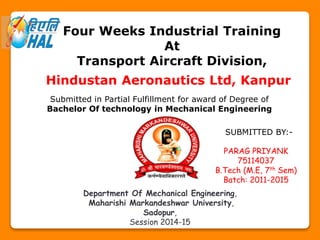
- 1. Four Weeks Industrial Training At Transport Aircraft Division, Hindustan Aeronautics Ltd, Kanpur Submitted in Partial Fulfillment for award of Degree of Bachelor Of technology in Mechanical Engineering SUBMITTED BY:- PARAG PRIYANK 75114037 B.Tech (M.E, 7th Sem) Batch: 2011-2015 Department Of Mechanical Engineering, Maharishi Markandeshwar University, Sadopur, Session 2014-15
- 2. DOWN THE YEARS Hindustan Aeronautics Limited is the outcome of merging of Hindustan Aircrafts Limited and Aeronautics India limited with Aircraft Manufacturing Depot, Kanpur and came into existence in Bangalore in 1940. Formerly it was in the hand of Seth Walchand. The Indian Government bought a one-third stake in the company and by April 1941 as it believed this to be a strategic imperative. Hindustan Aeronautics Limited (HAL) was formed on 1 October 1964 when Hindustan Aircraft Limited joined the consortium formed in June by the IAF Aircraft Manufacturing Depot, Kanpur (at the time manufacturing HS-748 under license) and the group recently set up to manufacture Mig-21 under license (with its new factories planned in Koraput, Nasik and Hyderabad). During the 1980s, HAL's operations saw a rapid increase which resulted in the development of new indigenous aircraft such as the HAL Tejas and HAL Dhruv. HAL also developed an advanced version of the MiG-21, known as MiG-21 Bison, which increased its life-span by more than 20 years. HAL has also obtained several multi-million dollar contracts from leading international aerospace firms such as Airbus, Boeing and Honeywell to manufacture aircraft spare parts and engines.
- 3. MILESTONES 1. Today, HAL has 19 Production Units and 10 Research & Design Centers in 8 locations in India. 2. The Company has an impressive product track record - 15 types of Aircraft/Helicopters manufactured with in-house R & D and 14 types produced under license. 3. HAL has manufactured over 3658 Aircraft/Helicopters, 4178 Engines, upgraded 272 Aircraft and overhauled over 9643 Aircraft and 29775 Engines. 4. Turnover of Rs. 15,180 Crore. 5. Has played an important role in development of SLV for ISRO 6. Bagged many awards by international giants of this sector. 7. Has started 11 joint-ventures to cope with the technical advancement in world. 8. Successfully established own composite and plastic manufacturing divisions. 9. Started designing and development of multirole aircraft. 10. Primary exporter of Pax doors to AIRBUS. 11. Successfully manufactured Light Combat Helicopters and Aircrafts
- 4. DIVISIONS 1. Aircraft Division, Bengaluru 2. Aerospace Division, Bengaluru 3. Aircraft Division, Nasik 4. Aircraft Overhaul Division, Nasik 5. Engine Division, Bengaluru 6. FMD, Bengaluru 7. F&F Division, Bengaluru 8. Engine Division, Koraput 9. Sukhoi Engine Division, Koraput 10. TAD, Kanpur 11. Avionics Division, Korwa (Amethi) 12. Avionics Division, Hyderabad 13. Accessories Division, Lucknow 14. Helicopter Division, Bengaluru 15. Helicopter Division, Barrackpore 16. CMD, Bengaluru 17. H-MRO Division, Bengaluru
- 5. PRODUCTS AT A GLANCE HAL-CHEETAL HAL- DHRUV HAL- CHEETAH HAL - LCH HAL- CHETAK HAL- LANCER
- 6. HAL – SUKHOI 30 MKI HAL – MIG 27 HAL – MIG 21 HAL - DORNIER HAL - IJT HAL – ADOUR mk 811 HAL – Artouste III B HAL - DART HAL – GARRETTE 331
- 7. HAL – GNOME 1400 PT HAL - AVON HAL – OREPHUS 7075 HAL – ADOUR MK 804 HAL - MIRAGE HAL – JAGUAR HAL – GSLV HAL – R 29 B HAL – R 25
- 8. Well the list of the products is very long, but some more important product for which HAL is known worldwide are following:- PAX DOORS (For Airbus A 320) LANDING GEARS CANOPY MISSILES DRONES (Un-maned Air Vehicle) ENGINE FUEL CONTROL SYSTEM TEMPERATURE SENSORS RUBBER ITEMS BRAKES HYDRAULIC PUMP STARTER GENERATOR ACCESSORIES FLIGHT DATA RECORDER AIR DATA COMPUTER
- 9. KANPUR DIVISION In this division there is total emphasis being made on the Transport Aircrafts which means the aircraft that are used for transport purpose. This division was set-up in 1960 to manufacture HS-748, but with the passage of the time the division has vastly developed infrastructure and built its technological force to manufacture varieties of aircrafts, structural assemblies, paint shop and detailed part manufacturing of various components. Following are ongoing work in this division:- HS-748 Aircraft Overhaul Dornier-228 Aircraft (1985 onwards) IJT Structural Assembly Following were the plane which were developed in this division but are obsolete now:- HS-748 Aircraft 1960-83 Gliders 1963-86 Basant Aircraft (HA-31) 1975-78 HPT-32 Aircraft 1983-98 ATP Tailplane (for Export) 1987-95
- 10. Apart from the above, this division is doing servicing of engines and landing gears of Unmanned Air Vehicles (Searcher-I and Searcher-II) and Heron since Jan’2004. Even this division has the R&D center located in the campus which carries out production updates, role modification and other related activities. Recently the division has undergone for the LSP (limited series production) for Intermediate Jet Trainer (IJT) aircraft which is used for training, night flying and patrolling purposes. The structural assembly is done here and all other fitments of engine, rudder and other avionics items are made in the Bengaluru Division. This plane is totally scrutiny over this division all deflections are checked and maintained by R&D department (wing of DRDO). Over the decades this division has equipped itself with ample of workforce to meet the demand and the goals. There are some of the future plans like:- Production of 14 seater Saras Aircraft Series production of 100 seater Multirole-Transport Aircraft Series production of Intermediate Jet Trainer (HJT-36) Production of Turbo-Prop Trainer aircraft (HTT-40)
- 11. There are various departments inside HAL, Kanpur which are integrated and have cohesion so that there is smooth flow in manufacturing and less deflection according to the demand. Following are the various departments:- Dornier-228 Manufacturing Dornier-228 Maintenance and Servicing Intermediate Jet Trainer Structure Assembly HS-748 Overhaul HPT-32 UAV Engine Maintenance Avionics Electronics Information Center Data Center Workshop(CNC, NC, Unconventional and Conventional Processes) Paint Shop Human Resource Detailed Part Manufacturing R&D Department
- 12. Central Library Powerhouse Rotables Technical Training Institute Tool Room Spare Parts HAL – Intermediate Jet Trainer IJT (Intermediate Jet Trainer) is also known as HJT-36 or Sitara. This aircraft is basically a two-seater aircraft where the trainee pilot seats in front and the instructor in rear. It has a jet engine. This aircraft is basically used for training, night flying and surveillance purpose. Its speed is .75 MK almost 750 km/hr. The student pilot who completes training successfully can fly in the fighter jet aircraft of Indian Air Force without any doubt. This plane is sub-sonic. This aircraft is half produced in the Kanpur division and half in the Bengaluru division.
- 13. HAL started design work on IJT in 1997. The concept was developed as a successor to earlier trainer, the HJT-16 Kiran. The first and second prototypes labeled PT-1 and PT-2 flew on 7 March, 2003 and March 2004 respectively. After further development on engines and extensive testing the Indian Air Force placed an order for 73 aircraft. After 280 test flights, the aircraft entered in Limited Series Production in 2009. In the Kanpur division the structural assembly is done, meaning that development of front fuselage, rear fuselage and wings and then they are assembled and moved to Bengaluru division for the installation of engine and other equipment after which the aircraft will roll out of the production process. FRONT FUSELAGE There are four front fuselage jig. In the front fuselage the structure starting from nose to the rear seating area is assembled. In this section there are stations mentioned on jig. The station denoted as STA N X starts from 0 to 23 in the front fuselage area. The X denotes the flight direction towards the nose of the aircraft and N denotes the number of station. There are longerons/stringers and bulk-heads used to make the skeleton of the aircraft.
- 14. In the front section of the aircraft there are 23 bulkheads which are vertical in direction positioned at different X values. The skeleton structure is also known as spine structure. The spine structure is totally riveted with the help of snap head rivet, counter sunk rivet. The diameter of the rivet may vary from 2.7mm to 4.8mm. The riveting is done with the help of pneumatic riveting device. In the front fuselage the part from STA 0 to STA 1 X=1250 (mm) is known as Nose cone and consists of 10 longerons. From STA 10 to STA23 there is seating area. The front fuselage extends from STA 1 X=1250(mm) to STA 23 X = 5390(mm). After the spine structure is ready the skin is fixed on this structure with the help of rivet and the sealant. The sealant may be 1422B2, 1770 or 8012. Pic of Front Fuselage
- 15. REAR FUSELAGE Rear fuselage of this aircraft starts from STA 24 X= 5690 to STA 42 X= 10770. The rear fuselage is very long. There are 18 bulkheads in the rear fuselage and 12 longerons. There are 4 shear-walls between STA 26 to STA 29 and STA 29 to STA 34 which provides strength to the structure. Between STA 24 to STA 29 there is fuel tank of capacity 550 ltr. Between STA 29 to STA 32 is the brake assembly. STA 32 to STA 35 provision of fitment. STA 24, STA 26 and STA 29 are wing built up-point during coupling for fixing the wings on both the sides of this rear fuselage. And the rest of the structure consists of exhaust manifold. The rear fuselage starts from air intake manifold and ends at the last tail point of the aircraft. REAR FUSELAGE
- 16. WINGS The wing is conventional and low setting. The total wing span of this aircraft is 9.8 meters. A wing also consists of the skeleton structure but is different. It consists of Spar and ribs. Ribs are the small and are like the bulk heads and spar are like longerons running from starting to the tip of the wings. There are 5 spar and 18 ribs. The various spars are front spar, rear spar and others. The wings are also completed with the help of Jig known as Wing Assembly Jig. The wing starts from station 1 to station 18. The measurement of the wing is STA 1 X= 350 to STA 18 X= 4547.7. After the successful assembly of the structure of the wing the leading edge and trailing edge of the wing is fixed on the structures with the help of rivets and sealant. Also the wings of this aircraft contains internal fuel tank of 175 ltrs each, means a total of 350 ltrs. Also it can carry an external fuel tank of 235 ltrs on each side meaning total external fuel 470 ltrs.
- 17. COUPLING After completion of the above works each aircraft is assembled at COUPLING JIG and all the respective parts meets the aircraft here. At this floor all the four components Rear fuselage, Front fuselage and both the wings arrive here are fixed. This is also called as MEETING POD. Here all the four basic components of aircraft are bolted together with bolts of high strength. After the completion of this coupling the body is transported to the BANGLORE DIVISION with the help of freightliner aircrafts where it meets it all other equipment and auxiliary like engine, landing gears, avionics and others. The structure developed after this assembling process is known as SKELETON STRUCTURE. ENGINE Engine used is “SATURN- AL- 551”. Developed by: JSC "NPO" Saturn " Production: JSC "NPO" Saturn "in cooperation with JSC" UMPO "AL-551 - turbofan engine for training and light combat aircraft. Engine design allows you to create on its base engine family for various purposes traction from 1500 to 5000 kgf. You can also create modifications base engine nozzle equipped with thrust vector control, as well as an afterburner. .
- 18. Features are 3-stage low-pressure compressor, 5-stage high-pressure compressor, annular combustion chamber, 1 speed high-pressure turbine, 1 speed low-pressure turbine. Application On database engine AL-55 engine created Saturn AL-55I for training aircraft HJT-36 development corporation HAL (India). The first flight of HJT-36 took place on 9 May, 2009. Implement made by company for license production of AL-55I in India. Engine family on the basis of the gas generator of the AL-55 can be mounted on various types of modern aircraft like trainer aircraft for basic training, advanced drones, trainer and light combat aircraft, Lightweight front- line fighters. Benefits are latest designs and materials, including tested on a family of engines AL-31F / FS and 117C, modular engine design provides high maintainability, reducing operating costs, modern automatic control system ensures the safety of the engine flying and easy maintenance. SATURN AL - 551
- 20. THREE VIEWS OF INTERMEDIATE JET TRAINER PICTURE of IJT
- 21. Labeled diagram of IJT
- 22. TECHNICAL SPECIFICATIONS Overall Length – 11 m Height (rudder) - 4.4 m Wing Span – 10 m Vision of front pilot over nose- 18 degree Fuselage Length – 11 m Max. Width ( without intake) – 1 m Vision of rear pilot – 8 degree Fuselage fuel Capacity – 550 kg Wing fuel Capacity – 175 kg/wing External fuel Capacity – 470 kg Total fuel Capacity – 1370 kg Maximum range with external fuel – 1510 km Maximum range with internal fuel - 1055 km Maximum altitude – 6 km Clean Aircraft Weight – 4250 kg Max. all up weight – 5400 kg
- 23. PERFORMANCES:- Max. Speed/ Mach No. - 750 km/hr/ .75 Max. rate of climb > 1500m/min STAL speed (clean configuration) < 185km/hr Take off run < 500m Landing Roll < 500m SALIENT FEATURES:- State of art, DC-Novo Design Tandem Seating arrangement Conventional configuration with good flying qualities Simple mechanical systems Manual control New modern turbo fan engine Active Matrix LCD Simple HUD with HUD repeater for rear cockpit Failure simulation from rear cockpit Command mode ejection
- 24. Zero-Zero ejection seat Effective training Ergonomically spacious designed cockpit Adequate internal fuel for normal training Data recording High thrust to weight ratio engine Low specific fuel consumption Digital FADEC and hydro-mechanical backup system Easy removal On condition maintenance, high reliability and maintainability ROLES:- Pilot Training General flying Navigation formation flying Instrument & cloud flying Basic air to ground & air to air aiming Tactical flying Night flying
- 25. DORNIER The Dornier Do 228 is a twin-turboprop STOL utility aircraft, manufactured by Dornier GmbH (later DASA Dornier, Fairchild-Dornier) from 1981 until 1998. In 1983, Hindustan Aeronautics (HAL) bought a production licence and manufactured 117 aircraft for the Asian market sphere. Approximately 270 Do- 228 were built at Oberpfaffenhofen, Germany and Kanpur, India. In August 2006, 127 Dornier Do 228 aircraft (all variants) remain in airline service. This is an Un-pressurised aircraft with Service Ceiling of 25000ft – 28000 ft easily, but after 16000ft there is need of oxygen from external sources for individual travelling in this aircraft.
- 26. FRONT FUSELAGE The fuselage of the DORNIER is made of 7075 aluminium which is an aluminium alloy, with zinc as the primary alloying element. It is strong, with a strength comparable to many steels, and has good fatigue strength and average machinability, but has less resistance to corrosion than many other Al alloys. Its relatively high cost limits its use to applications where cheaper alloys are not suitable. 7075 aluminum alloy's composition roughly includes 5.6–6.1% zinc, 2.1–2.5% magnesium, 1.2–1.6% copper, and less than half a percent of silicon, iron, manganese, titanium, chromium, scandium and other metals. The front fuselage extends after nose cone that is STA 1 X= 1200mm to STA 12 X = 5420m where X denotes the flight direction. In this fuselage there is upper section and lower section which are joined together. The front fuselage basically consists of cockpit.
- 27. CENTER FUSELAGE The center fuselage extends from STA 13 X = 5480mm to STA 24 X= 10680mm. There are two parts of the center fuselage namely center fuselage front section and center fuselage rear section. This section of aircraft is basically used for passenger/crew seating arrangement or material store which is to be transported. REAR FUSELAGE Rear fuselage extends from STA 25 X= 11000mm to STA 34 X = 16560mm. This section is also known as tail section of the aircraft and is converging. It consists of dorsal fin, tail plane, vertical stabilizer, horizontal stabilizer, elevator. WING This aircraft is high-wing aircraft which means that the wings are attached to the upper section of center fuselage. The total wing span is 16.97 m. The wing consists of one turbo-prop engine on each side. . There are front, top, bottom and rear spar and 19 ribs. The wing stretches from STA 1 X = 000mm to STA 19 X = 8485mm
- 28. Both the wings are equipped with flaps and ailerons which are used during climb and decent. The flaps and aileron provides the aircraft to take-off and to glide in air and to land.
- 29. HORIZONTAL STABILIZER The working of horizontal stabilizer is to give aircraft desired pitch for take-off and climb due to varying conditions. This is located at tail of the aircraft. It is controlled with the help of hydraulic system using trimmer. The pitch that is the angle of horizontal stabilizer is fixed before take-off as per the operating conditions. The horizontal stabilizer consists of the elevator which moves up and down providing the desired airflow at the tail. This elevator also comprises of trim tab which is used when aircraft needs small vertical climb or decent. VERTICAL STABILIZER The vertical stabilizer is one standing vertically at tail of the aircraft. It is joined with the fin of the aircraft. The vertical stabilizer is responsible for functioning of aircraft in mid-air. RUDDER TRIM & TAB The rudder is that component of aircraft which is responsible for the turning of aircraft in the air. The rudder is operated from the help of rudder pedal provided at the nose cone of the cockpit. This rudder also comprises of the trim tab which is used when there is need of small deflection in direction.
- 30. Diagram Showing all the basic components of aircraft discussed above ENGINE The Garrett AiResearch TPE331 is a turboprop engine originally designed and manufactured by Garrett AiResearch, and produced by Honeywell Aerospace since 1999 after that company acquired Garrett. It is a 2 stage centrifugal compressor and 3 stage axial turbine engine. It produces maximum 715 horsepower which is ample to throw this aircraft into air.
- 31. Basic diagram of Turbo-Prop Engine In the beginning the propellers blade are at 18 degree that is on-lock condition and when the maximum power is required the angle is increased to 78 degree. In this engine there are 15 fuel sprayers in which 5 are primary and 10 are secondary. There are two spark plugs in the combustion chamber. This is a spark ignition engine and use aviation turbine fuel. It also has 2 boosters and oil dumper unit using a solenoid and non-return valve. The engine power provides the THRUST to the aircraft which makes it to move and further the air profile inside wing helps it to the lift.
- 32. COCKPIT The cockpit of the aircraft contains all the control systems and indicators. Some of them are:- PUSH PULL ROD RUDDER PEDAL/BRAKE RUDDER TRIM AIR SPEED INDICATOR VERTICAL SPEED INDICATOR TURNING & ROTATING SPEED INDICATOR MICROPHONE BUTTON RUDDER TRIM AUTO PILOT NAVIGATION MODE CENTRAL WARNING SYSTEM GPS ENGINE CONTROL LANDING GEAR CONTROL LAT- LONG SYSTEM FLIGHT DATA RECORDING
- 34. LANDING GAER The total number of wheels in the landing gear is 4. The nose landing gear consists of 2 wheels and the rear landing gears contain one wheel on either side. The landing gear is hydraulic and operated with the help of motor. The hydraulic fluid used in the landing gear comprises of hydraulic oil & nitrogen. The tire pressure for rear landing gear should be maintained to 72 psi and in front tires the pressure must not exceed maximum value of 62 psi. The brakes are controlled with the rudder pedal. In the brakes there are 6 pistons which are operated with the help of hydraulics. If in the case the landing gear is not working then a backup system already stored in the aircraft is used. This backup system consists of compressed nitrogen stored in the cylinder with a pressure of 2400 Psi. PAINTING For this aircraft the painting time taken is one week often. In the painting process first the structure is cleaned and then a H-primer one time is coated. After 24 hours the coat of an epoxy primer is applied and then the two coats of Poly-Urethane paint are applied within quick succession of 72 hours. Different agencies have their own painting styles. Thus it is not very easy to paint two aircraft for different customers at a single time. The painting is done with the help of manual spray.
- 35. PROCESS CHART NOSE SECTION Front Fuselage Upper Section Front Fuselage Lower Section Center Fuselage Rear Fuselage ASSEMBLING Vertical Stabilizer Horizontal Stabilizer Wings, Flaps, Ailerons & Elevator ENGINE Landing Gears Chairs, Doors, Wind Screens QCD OF DRDO PAINTING
- 37. TECHNICAL SPECIFICATIONS Wing Span – 16.97 m Overall Length – 16.56 m Overall Height – 4.86 m Engine Model – Garrett TPE 331-5-252 D Take-off power – 2 x 715 SHP flat rated to ISA Propeller type – Hartzell four-bladed Propeller Diameter – 2.69m Fuel Capacity – 2850 ltrs ( 2250 kg) Fuel Consumption – 213 kg/hr Weights:- Max. Take-off Weight Maritime Role - 6400 kg Commuter Role – 6200 kg Max. Landing Weight – 6100 kg Max. Zero fuel Weight – 5590 kg
- 38. ROLES:- Maritime Surveillance Pollution Prevention Troop Transport Aerial Survey Search and Rescue Commuter Transport Calibration of airport NAV-COM aids Remote Sensing Applications Casuality Evacuation Executive Transport Cargo & Logistics Support
- 39. LESSON EARNT The most important lesson what I have learnt here is that how to keep in cohesion with each other and work for the best output in the time when your competitors are just not following but trying to pull you down. The discipline and the keen and magnanimous “love with the work” and cohesion and team spirit have been a lesson that inspired me more in my whole training period. Well apart from this the lesson what has been in-housed in me was from the section in what I was training. The manufacturing of Intermediate Jet Trainer and DORNIER is totally captured in me. I saw the pupils having high moral and total enthusiasm while working. The workforce of Kanpur division not only comprises of better work force but also a workforce that has cohesion among all the level of workers. My moral has become all time high and it only means achieve goals in life ahead.