
Recommended
More Related Content
What's hot
What's hot (20)
Viewers also liked
Viewers also liked (15)
Similar to Homework1 ogo8842
Similar to Homework1 ogo8842 (20)
Homework1 ogo8842
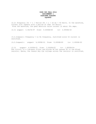
- 1. CSCE 585 FALL 2014 ASSIGNMENT 1 OLADIRAN OLALEYE Ogo8842 (2.2) Frequency (f) = 1 / Period (T) = 1 / 20 ms = 50 Hertz. In the waveform, current also repeats with a period of 20ms (50 Hertz). From the waveform, the peak absolute value current is about 30u amps. (2.3) avgpwr= 3.3417E-07 from= 0.0000E+00 to= 2.0000E-02 (3.2.2repeat): Frequency = no No frequency. Justified since th current is rectified. (3.2.3repeat): avgpwr= 4.5000E-01 from= 0.0000E+00 to= 2.0000E-02 (3.3) avgpwr= 4.5000E-01 from= 3.0000E+02 to= 1.8000E+04 The circuit is a low-pass filter and blocks AC but passes DC to the Rload resistor. Hence, the reason why the voltage across the resistor is rectified.
- 2. *Assignment 1/Question 1 Netlist/ogo8842 .INCLUDE 'tsmc18.sp' VVin1 Vin 0 PULSE(0 1.8 0u 10n 10n 200u 400u) V2 nVR 0 1.8V MMOS Vout Vin 0 0 nfet L=0.18u W=0.36u RRes nVR Vout 25kohm CCap Vout 0 4nF .TRAN 1ns 800us .PROBE TRAN V(Vin) V(Vout) .OPTIONS list node probe post .END
- 4. *Assignment 1/Question 2 Netlist/ogo8842 VVin nVR 0 PULSE(0 1.8 0u 50n 50n 10m 20m) R1 nVR nRL 10kohm LL1 nRL nLC 5H CC1 nLC 0 2nF .TRAN 1ns 20ms .PROBE TRAN I(R1) .MEASURE TRAN avgpwr AVG power from=0s to=20m .PRINT avgpwr .OPTIONS list node probe post .END
- 5. *Assignment 1/Question 3 Netlist/ogo8842 VV1 2 1 ac 30V sin VV2 1 0 dc 30V LL1 2 3 150mH LL2 3 4 200mH RR1 4 0 2kohm CC1 3 0 150uF .ac lin 40 300Hz 18kHz .PROBE ac V(4,0) .MEASURE ac avgpwr AVG power from=300Hz to=18kHz .PRINT avgpwr .OPTIONS list node probe post .END
- 6. *Assignment 1/Question 3.2repeat Netlist/ogo8842 VV1 2 1 ac 30V sin VV2 1 0 dc 30V LL1 2 3 150mH LL2 3 4 200mH RR1 4 0 2kohm CC1 3 0 150uF .TRAN 1ns 20ms .PROBE TRAN I(RR1) .MEASURE TRAN avgpwr AVG power from=0s to=20m .PRINT avgpwr .OPTIONS list node probe post .END
- 7. *Assignment 1/Question 4 Netlist/ogo8842 Vin 1 0 AC 1 SIN(0V 1V 15kHz) *Vout nR3Z4, nR1Z2 0V LZ1 nZ1R1 1 100mH LR1 nR1Z2 nZ1R1 10oHm LZ2 nZ2R2 nR1Z2 100mH LR2 nR20 nZ2R2 10oHm LZ3 nZ3R3 1 100mH LR3 nR3Z4 nZ3R3 10oHm LZ4 nZ4R4 nR3Z4 100mH LR4 nR40 nZ4R4 10oHm .TRAN 1ns 10us .PROBE TRAN V(1, 0) V(nR3Z4, nR1Z2) .OPTIONS list node probe post .END