Gfe Mayur Vihar Call Girls Service WhatsApp -> 9999965857 Available 24x7 ^ De...
Plan PCI.docx
1. Plan PCI at (05) easy steps with Atoll !!
You are looking to plan PCI for your LTE cluster ? do not get in panic and here is
the (05) steps to do that in Atoll !
›The Physical Cell Identity is an essential configuration parameter of a radio cell in
LTE and It identifies the cell in cell search. The main objective of PCI planning is to
ensure that all cells are correctly identified.
›There are 504 physical cell identities.
›These are made up of :
–168 cell identity groups with 3 identities each
–168×3=504 physical cell identities
–PCI =Sub Cell ID + 3 x Cell ID Group
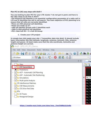
1. Create your LTE project
In simple two click paste your site / Transmitter data into Atoll. It should include
basic information like Site latitude, longitude, antenna, Azimuth, tilts, antenna
height and power. At least make sure that the site coordinate, Azimuths and
antenna height are correct.
https://media-exp1.licdn.com/dms/ima...7mnTA8Rp2z2m8s
2. https://media-exp1.licdn.com/dms/ima...n2bp1rvQ4EnbYw
2. Core area definition
Create the focus zone (core area) which is the area we want to plan PCI or change
the existing PCI Plan ! it is showing in "green color" polygon. Make sure that
buffer area (remaining cells) are having an existing PCI plan.
https://media-exp1.licdn.com/dms/ima...uHmsGUJLzWYoXw
3. Neighbor list planning
To avoid assigning the same PCI plan within neighbors of the cells, it is
recommended to create your neighbor plan prior running the PCI Plan!.
Below figures illustrate the steps to create the neighbor plan.
https://media-exp1.licdn.com/dms/ima...3y9-azPl9S5wTc
3. An Example of recommended setting is showing below. Hit the button "Calculate"
.. the neighbor are calculated as shown in below figure. If happy then, commit the
change.
https://media-exp1.licdn.com/dms/ima...QymJtc0hn5oOIM
4. Check quickly the neighbor plan and that can be performed as showing in below
figu:
https://media-exp1.licdn.com/dms/ima...GCaMW353JYKfVE
5. 4. Run PCI Planning
Before running the PCI, need to set PSS & SSS ID Status to "Not Allocated".
"Not Allocated" : Any PCI can be modified without any cost.
"Allocated" : the PCI is modifiable only if absolutely necessary.
"Locked" : The PCI not modifiable.
https://media-exp1.licdn.com/dms/ima...V-wLEcYHK7_U0Y
6. Time to run the PCI Plan. Following figure is showing how to do that !
https://media-exp1.licdn.com/dms/ima...OFkLt4t0vp4-fA
7. Mainly and depends on site to site distance, the reuse distance can be set
accordingly. In Rural area the PCI reuse distance can be set to higher value.
As the reference Signal (RS) position in the Resource Block (RB) is decided by the
output of PCI mod 6, it is good to put some wight for PCI mod 6 and for PCI Mod
30 (UL DMRS).
https://media-exp1.licdn.com/dms/ima...K4Vv8GS28h4wEA
8. Also, it is important to check what is the current PCI step used by the operator
and if it is fresh PCI planning , I recommend to use PCI Step 8
There are two type of Pci planning steps:
Non-shifted: PCIi mod 6 same for all cells within the site
Shifted: PCIi mod 6 different for all cells within the site
Below are some example of RS shifted and no shifted scenario:
STEP 1: shifted + same PCI group within site
Example: CI (PSS) = 0,1,2; PCI Group (SSS) = 10
10x3 + 0 = 30
10x3 + 1 = 31
10x3 + 2 = 32
STEP 6: non-shifted + different PCI group within site
Example: CI (PSS) = 1; PCI Group (SSS)= 3,5,7
3x3 + 1 = 10
5x3 + 1 = 16
9. 7x3 + 1 = 22
STEP 8: shifted + different PCI group within site
Example: CI (PSS) = 1,0,2; PCI Group (SSS) = 3,6,8
3x3 + 1 = 10
6x3 + 0 = 18
8x3 + 2 = 26
In PCI Step 1 & 8, the PCI mod 6 is different for all cells within a site.
Basically in non-shifted RS, the RS in adjacent cells will cause the situation that
the RSs will interfere only each other and in shifted RS, the RS will cause
interference on PDSCH resource element.
Once all is set, hit the "start" button.. the PCI plan will run and changes are
showing in blue color. Once completed , "Commit" the change.
https://media-exp1.licdn.com/dms/ima...ATKxM0WAwzf6JU
5. PCI Plan output check
Use Atoll Audit module to calculate the different collision reuses and the main
reuses to be checked is "Physical Cell ID Collision" and the "PCI Mod 6 Collision"
with small reuse distance.
https://media-exp1.licdn.com/dms/ima...-_86RpVH9oseZo
10. Below figure is showing an audit report calculated for the same cluster. For
example some cases with PCI Mod 6 collision within 138 m which need to be
checked if the sectors are looking to same direction !
13. Rachid Lamali
Solution Architect at Ericsson & RF planning tools expert
10 articles Follow
You are looking to plan PCI for your LTE cluster ? do not get in panic and here is the (05)
steps to do that in Atoll !
›The Physical Cell Identity is an essential configuration parameter of a radio cell in LTE and
It identifies the cell in cell search. The main objective of PCI planning is to ensure that all
cells are correctly identified.
›There are 504 physical cell identities.
›These are made up of :
–168 cell identity groups with 3 identities each
–168×3=504 physical cell identities
–PCI =Sub Cell ID + 3 x Cell ID Group
1. Create your LTE project
In simple two click paste your site / Transmitter data into Atoll. It should include basic
information like Site latitude, longitude, antenna, Azimuth, tilts, antenna height and power.
At least make sure that the site coordinate, Azimuths and antenna height are correct.
14.
15. 2. Core area definition
Create the focus zone (core area) which is the area we want to plan PCI or change the
existing PCI Plan ! it is showing in "green color" polygon. Make sure that buffer area
(remaining cells) are having an existing PCI plan.
16. 3. Neighbor list planning
To avoid assigning the same PCI plan within neighbors of the cells, it is recommended to
create your neighbor plan prior running the PCI Plan!.
Below figures illustrate the steps to create the neighbor plan.
17. An Example of recommended setting is showing below. Hit the button "Calculate" .. the
neighbor are calculated as shown in below figure. If happy then, commit the change.
18.
19. Check quickly the neighbor plan and that can be performed as showing in below figu:
4. Run PCI Planning
Before running the PCI, need to set PSS & SSS ID Status to "Not Allocated".
"Not Allocated" : Any PCI can be modified without any cost.
"Allocated" : the PCI is modifiable only if absolutely necessary.
"Locked" : The PCI not modifiable.
20. Time to run the PCI Plan. Following figure is showing how to do that !
21. Mainly and depends on site to site distance, the reuse distance can be set accordingly. In
Rural area the PCI reuse distance can be set to higher value.
As the reference Signal (RS) position in the Resource Block (RB) is decided by the output of
PCI mod 6, it is good to put some wight for PCI mod 6 and for PCI Mod 30 (UL DMRS).
22.
23. Also, it is important to check what is the current PCI step used by the operator and if it is fresh
PCI planning , I recommend to use PCI Step 8
There are two type of Pci planning steps:
Non-shifted: PCIi mod 6 same for all cells within the site
Shifted: PCIi mod 6 different for all cells within the site
Below are some example of RS shifted and no shifted scenario:
STEP 1: shifted + same PCI group within site
Example: CI (PSS) = 0,1,2; PCI Group (SSS) = 10
10x3 + 0 = 30
10x3 + 1 = 31
10x3 + 2 = 32
STEP 6: non-shifted + different PCI group within site
Example: CI (PSS) = 1; PCI Group (SSS)= 3,5,7
3x3 + 1 = 10
5x3 + 1 = 16
7x3 + 1 = 22
STEP 8: shifted + different PCI group within site
Example: CI (PSS) = 1,0,2; PCI Group (SSS) = 3,6,8
3x3 + 1 = 10
6x3 + 0 = 18
8x3 + 2 = 26
In PCI Step 1 & 8, the PCI mod 6 is different for all cells within a site.
Basically in non-shifted RS, the RS in adjacent cells will cause the situation that the RSs will
interfere only each other and in shifted RS, the RS will cause interference on PDSCH resource
element.
24. Once all is set, hit the "start" button.. the PCI plan will run and changes are showing in blue
color. Once completed , "Commit" the change.
25. 5. PCI Plan output check
Use Atoll Audit module to calculate the different collision reuses and the main reuses to be
checked is "Physical Cell ID Collision" and the "PCI Mod 6 Collision" with small reuse
distance.
26. Below figure is showing an audit report calculated for the same cluster. For example some
cases with PCI Mod 6 collision within 138 m which need to be checked if the sectors are
looking to same direction !