C010421720
•
0 likes•104 views

The document discusses a built-in self-detection and correction (BISDC) architecture for motion estimation computing arrays (MECAs) used in video coding systems. It proposes using biresidue error correcting codes to detect and correct single bit errors in each processing element of the MECA with minimal area overhead. The BISDC architecture achieves online error detection and correction through test code generation, detection and selection circuits, syndrome decoding, and error correction circuits. Performance analysis shows the approach effectively detects and corrects errors while introducing minor additional circuitry.
![Design and Tetability of Video CodingSystem by Using Meca
DOI: 10.9790/2834-10421720 www.iosrjournals.org 18 | Page
receive data from a specific PEi+1, and then export these data to the next specific PEi or syndrome analysis and
corrector (SAC) for error correction. Based on the concepts of BIST and biresidue codes, this paper presents a
built-in self-detection/correction (BISDC) architecture that effectively self-detects and self-corrects PE errors in
an MECA.Notably, any array-based computing structure, such as the discrete cosine transform (DCT), iterative
logic array (ILA), and finite-impulse filter (FIR), is suitable for the proposed method to detect and correct errors
based on biresidue codes.
2.2 Fault Model: The PEs are important building blocks and are connected in a regular manner to construct an
MECA. Generally, PEs are surrounded by sets of adders and accumulators that determine how data flows
through them. Thus, PEs can be considered the class of circuits called ILAs, whose testing assignment can be
easily achieved using the fault model called as cell fault model (CFM). The use of the CFM is currently of
considerable interest due to the rapid growth in the use of high-level synthesis and the parallel increase in
complexity and density of ICs. Using the CFM allows tests to be independent of the adopted synthesis tool and
vendor library. Arithmetic modules, like adders (the primary element in a PE), due to their regularity, are
designed in a very dense configuration.
Moreover, the use of a relatively more comprehensive fault model, the single stuck-at (SSA) model, is
required to cover actual failures in the interconnect data bus between PEs. The SSA fault is a well-known
structural fault model that assumes faults cause a line in the circuit to behave as if it were permanently at logic
“0” [stuck-at 0 (SA0)] or logic “1” [stuck-at 1 (SA1)]. The SSA fault in an MECA architecture can result in
errors in computed SAD values. This paper refers to this as a distorted computational error; its magnitude is e =
SAD’-SAD. Where SAD’ is the computed SAD value with an SSA fault.
2.3 Elements involved in BIST: The self-detection and self correction operations (Fig.4.1) are simply described
as follows. First, the input data of Cur. Pixel and Ref.pixel for a specific PEi in the MECA are sent to the test
code generator (TCG) to generate the corresponding test codes. Second, the test codes from the TCG and output
data from the specific PEiare detected and verified in detector and selector (DAS) circuits to determine whether
the specific PEi has an error. In other words, the self-detection capability uses the detector circuit in DAS.
Third, the selector circuit in DAS delivers the error signal to SAC for error correction. Finally, the error
correction data from SAC, or error-free data from the selector circuit in DAS, are passed to the next specific
PEi+1for subsequent testing. 2.4 Processing Element (PE)
Processing element calculates the sum of absolute differences (SAD) between current pixels and
reference pixels. Generally, a PE is made up of two adders (an 8-bit adder and a 12-bit adder) and accumulator.
The SAD is given by
N-1 N-1
SAD = ΣΣ | C(r, j) – r(r, j) |
i=0 i=0
j=0 j=0
Where c (i, j) and r (i, j) are the current pixel and reference pixel. The 16 pixels absolute difference is given to
adder unit to perform SAD.
2.5 Coder: The following definitions, based on the bi-residues codes, are applied to verify the feasibility of the
two coders in the TCG
Definition 1: | N1+N2|φ = || N1| φ + |N2|φ| φ.
Definition 2: Let Nj= n1+n2+…………. +nj.
Then | Nj| φ = || n1| φ+ |n2| φ + ……. + | nj|φ|φ.
in the Project we are using two Coder modules because bi residue Codes are used for calculation of SAD. And
the Phi1 (φ1) and phi2 (φ2) values are selected by satisfying the conditions. i.e. A = 2a -1 and B = 2b -1 such
that GCD (a, b) = 1.
2.6 Detector: Detector module will detect whether there is an error in output of PE i.e. SAD. Here the Error is
calculated. The output of PE and theoretically calculated SAD will be subtracted which is given as e = SAD’-
SAD.
2.7 Selector : Selector takes the output of the processing element as an input. Another input to the selector is the
output of the detector. If the Detector block detects any error in the PE output then the Selector block will give
the PE output to Syndrome Decoder to detect in which bit position there is an error and also to the Corrector
block to correct the single bit error.](data:image/gif;base64,R0lGODlhAQABAIAAAAAAAP///yH5BAEAAAAALAAAAAABAAEAAAIBRAA7)
Recommended
Recommended
More Related Content
What's hot
What's hot (20)
Viewers also liked
Viewers also liked (12)
Similar to C010421720
Similar to C010421720 (20)
More from IOSR Journals
Recently uploaded
Recently uploaded (20)
C010421720
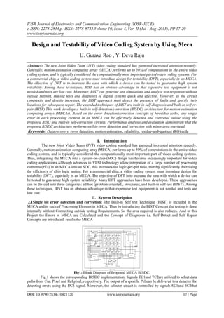
- 1. IOSR Journal of Electronics and Communication Engineering (IOSR-JECE) e-ISSN: 2278-2834,p- ISSN: 2278-8735.Volume 10, Issue 4, Ver. II (Jul - Aug .2015), PP 17-20 www.iosrjournals.org DOI: 10.9790/2834-10421720 www.iosrjournals.org 17 | Page Design and Testability of Video Coding System by Using Meca U. Gurava Rao , Y. Deva Raju Abstract: The new Joint Video Team (JVT) video coding standard has garnered increased attention recently. Generally, motion estimation computing array (MECA) performs up to 50% of computations in the entire video coding system, and is typically considered the computationally most important part of video coding systems. For a commercial chip, a video coding system must introduce design for testability (DFT), especially in an MECA. The objective of DFT is to increase the ease with which a device can be tested to guarantee high system reliability. Among these techniques, BIST has an obvious advantage in that expensive test equipment is not needed and tests are low cost. Moreover, BIST can generate test simulations and analyze test responses without outside support, making tests and diagnoses of digital systems quick and effective. However, as the circuit complexity and density increases, the BIST approach must detect the presence of faults and specify their locations for subsequent repair. The extended techniques of BIST are built-in self-diagnosis and built-in self-re- pair (BISR).This work develops a built-in self-detection/correction (BISDC) architecture for motion estimation computing arrays (MECAs). Based on the error detection/correction concepts of biresidue codes, any single error in each processing element in an MECA can be effectively detected and corrected online using the proposed BISD and built-in self-correction circuits. Performance analysis and evaluation demonstrate that the proposed BISDC architecture performs well in error detection and correction with minor area overhead. Keywords: Data recovery, error detection, motion estimation, reliability, residue-and-quotient (RQ) code I. Introduction The new Joint Video Team (JVT) video coding standard has garnered increased attention recently. Generally, motion estimation computing array (MECA) performs up to 50% of computations in the entire video coding system, and is typically considered the computationally most important part of video coding systems. Thus, integrating the MECA into a system-on-chip (SOC) design has become increasingly important for video coding applications.Although advances in VLSI technology allow integration of a large number of processing elements (PEs) in an MECA into an SOC, this increases the logic-per-pin ratio, thereby significantly decreasing the efficiency of chip logic testing. For a commercial chip, a video coding system must introduce design for testability (DFT), especially in an MECA. The objective of DFT is to increase the ease with which a device can be tested to guarantee high system reliability. Many DFT approaches have been developed. These approaches can be divided into three categories: ad hoc (problem oriented), structured, and built-in self-test (BIST). Among these techniques, BIST has an obvious advantage in that expensive test equipment is not needed and tests are low cost. II. System Description 2.1Single bit error detection and correction: The Built-in Self test Technique (BIST) is included in the MECA and in each of Processing Element in MECA. Thus by introducing the BIST Concept the testing is done internally without Connecting outside testing Requirements. So the area required is also reduces. And in this Project the Errors in MECA are Calculated and the Concept of Diagnoses i.e. Self Detect and Self Repair Concepts are introduced. results the MECA Fig1: Block Diagram of Proposed MECA BISDC. Fig.1 shows the corresponding BISDC implementation. Signals TC1and TC2are utilized to select data paths from Cur. Pixel and Ref.pixel, respectively. The output of a specific Pelican be delivered to a detector for detecting errors using the DC1 signal. Moreover, the selector circuit is controlled by signals SC1and SC2that
- 2. Design and Tetability of Video CodingSystem by Using Meca DOI: 10.9790/2834-10421720 www.iosrjournals.org 18 | Page receive data from a specific PEi+1, and then export these data to the next specific PEi or syndrome analysis and corrector (SAC) for error correction. Based on the concepts of BIST and biresidue codes, this paper presents a built-in self-detection/correction (BISDC) architecture that effectively self-detects and self-corrects PE errors in an MECA.Notably, any array-based computing structure, such as the discrete cosine transform (DCT), iterative logic array (ILA), and finite-impulse filter (FIR), is suitable for the proposed method to detect and correct errors based on biresidue codes. 2.2 Fault Model: The PEs are important building blocks and are connected in a regular manner to construct an MECA. Generally, PEs are surrounded by sets of adders and accumulators that determine how data flows through them. Thus, PEs can be considered the class of circuits called ILAs, whose testing assignment can be easily achieved using the fault model called as cell fault model (CFM). The use of the CFM is currently of considerable interest due to the rapid growth in the use of high-level synthesis and the parallel increase in complexity and density of ICs. Using the CFM allows tests to be independent of the adopted synthesis tool and vendor library. Arithmetic modules, like adders (the primary element in a PE), due to their regularity, are designed in a very dense configuration. Moreover, the use of a relatively more comprehensive fault model, the single stuck-at (SSA) model, is required to cover actual failures in the interconnect data bus between PEs. The SSA fault is a well-known structural fault model that assumes faults cause a line in the circuit to behave as if it were permanently at logic “0” [stuck-at 0 (SA0)] or logic “1” [stuck-at 1 (SA1)]. The SSA fault in an MECA architecture can result in errors in computed SAD values. This paper refers to this as a distorted computational error; its magnitude is e = SAD’-SAD. Where SAD’ is the computed SAD value with an SSA fault. 2.3 Elements involved in BIST: The self-detection and self correction operations (Fig.4.1) are simply described as follows. First, the input data of Cur. Pixel and Ref.pixel for a specific PEi in the MECA are sent to the test code generator (TCG) to generate the corresponding test codes. Second, the test codes from the TCG and output data from the specific PEiare detected and verified in detector and selector (DAS) circuits to determine whether the specific PEi has an error. In other words, the self-detection capability uses the detector circuit in DAS. Third, the selector circuit in DAS delivers the error signal to SAC for error correction. Finally, the error correction data from SAC, or error-free data from the selector circuit in DAS, are passed to the next specific PEi+1for subsequent testing. 2.4 Processing Element (PE) Processing element calculates the sum of absolute differences (SAD) between current pixels and reference pixels. Generally, a PE is made up of two adders (an 8-bit adder and a 12-bit adder) and accumulator. The SAD is given by N-1 N-1 SAD = ΣΣ | C(r, j) – r(r, j) | i=0 i=0 j=0 j=0 Where c (i, j) and r (i, j) are the current pixel and reference pixel. The 16 pixels absolute difference is given to adder unit to perform SAD. 2.5 Coder: The following definitions, based on the bi-residues codes, are applied to verify the feasibility of the two coders in the TCG Definition 1: | N1+N2|φ = || N1| φ + |N2|φ| φ. Definition 2: Let Nj= n1+n2+…………. +nj. Then | Nj| φ = || n1| φ+ |n2| φ + ……. + | nj|φ|φ. in the Project we are using two Coder modules because bi residue Codes are used for calculation of SAD. And the Phi1 (φ1) and phi2 (φ2) values are selected by satisfying the conditions. i.e. A = 2a -1 and B = 2b -1 such that GCD (a, b) = 1. 2.6 Detector: Detector module will detect whether there is an error in output of PE i.e. SAD. Here the Error is calculated. The output of PE and theoretically calculated SAD will be subtracted which is given as e = SAD’- SAD. 2.7 Selector : Selector takes the output of the processing element as an input. Another input to the selector is the output of the detector. If the Detector block detects any error in the PE output then the Selector block will give the PE output to Syndrome Decoder to detect in which bit position there is an error and also to the Corrector block to correct the single bit error.
- 3. Design and Tetability of Video CodingSystem by Using Meca DOI: 10.9790/2834-10421720 www.iosrjournals.org 19 | Page 2.8 Syndrome Decoder: This module decodes the syndrome values which specify the error in the bit position of SAD. Syndromes can be expressed as (Sφ1, Sφ2)= (|N’j-X|φ1, |N’j-Y|φ2) = (|e|φ1, |e|φ2) 2.9 Corrector: Input to the corrector module is the output of the selector module which is SAD that needs to be corrected; the bit position which needs correction is specified by the syndrome decoder. The corrector architecture consists of LUT and 12 multiplexers. III. Proposed Method Our design is intended to speed up the computation of the minimum SAD by its implementation on a FPGA (SAD processor in figure 1), while a core processor supplies the reference and candidate blocks to the FPGA device (dispatcher in figure 1). In this paper we propose a FPGA architecture to compute the minimum SAD. This design can be integrated with any BMA (full search or another efficient search strategy). On-line arithmetic techniques have been considered to solve many signal processing problems, such us digital filtering, Fourier transform and others [6] [9]. Recent works have presented the attractiveness of OLA for FPGAs designs. The MSD first mode of computation requires a flexibility in computing digits on the basis of partial information about inputs. This is achieved by the use of redundant representation system. In a redundant representation with radix r, each digit has more than r possible values. This allows several representation of a given value. Therefore, there is a flexibility in choosing an output digit at a given step so that, a compensation can be introduced if needed. SD representation system is used in this paper. In radix-2 SD representation, the digit set is {-1; 0; 1}. Two bits are required to represent each digit, as shown in Table 1. The first bit is negative weighted and the second one is positive weighted. This number system eliminates the long carry propagation chains in addition operation, although requires the carry of the two previous digits. In short, the advantages of using on-line arithmetic are: due to digit serial nature it reduces the number of signal lines connecting modules, the MSD first computation allows subsequent calculations to occur at much earlier stage, and it eliminates carry propagation chains since it uses a redundant number representation system. 3.1On-line computation of the minimum Sad: The candidate blocks (supplied by the dispatcher) best match the reference block. The most commonly used metric to determine the best match is the sum of absolute differences (SAD). Thus, our design compute the minimum SAD among all the candidate blocks. To do this, a search iteration is performed for each candidate block. On each search iteration, the SAD corresponding of a candidate block is computed using all its pixels simultaneously. The value obtained is compared with the reference SAD (SADr) which is the minimum SAD computed before this iteration. If the current SAD (SADc) is less than SADr, it is stored as SADr for the remaining search iterations. Both the SAD computation and comparison operation is performed using on-line arithmetic. This allows us to begin the comparison when the first digit of the SAD is obtained and early stop the computation if the digits computed are enough to ensure that SADc is greater than SADr. The SAD adds up the absolute differences between corresponding elements in the candidate and reference block IV. Figures And Tables Table1. Digit codification in radix-2 signed-digit representation Table This property is used to perform simultaneously the conversion of each pixel value to SD and the difference between pixels of reference block and current block with no computational cost. In that way, each digit of the value d(i,j) = c(i,j) r(i,j) is obtained in SD representation by only taking the corresponding bit of ci;j as the positive weighted and the corresponding bit of r(i,j) as the negative weighted, since c(i,j) and r(i,j) are unsigned numbers. Absolute value: To compute the absolute value of d(i,j) , the sign of this value have to be changed if di;j is negative. In SD the negation operation is performed by interchanging both bits of each digit.
- 4. Design and Tetability of Video CodingSystem by Using Meca DOI: 10.9790/2834-10421720 www.iosrjournals.org 20 | Page Figure Simulation Results of the Output module Since MSD-first mode of computation is used, the sign detection of d(i,j) is performed on-the-°y by checking if the first non zero digit of d(i,j) is positive (01) or negative (10). The digits of d(i,j) are received in MSD-first mode and go directly to the output while they are zero (00 or 11). If the first non zero digit received is positive (01), this and all the remaining digit correspond directly with the output. Nevertheless, if the first non zero digit received is negative (10), the bit of this and all the remaining digit are interchanged to obtain the output. The absolute value operation is performed with no online delay. Sum of absolute differences: The absolute difference of all the pixels corresponding to the current and reference blocks are computed in parallel. Then N2 absolute difference blocks are required. An on-line adder tree is used to obtain the sum of all d(i,j) values as given in fig 2. V. Results and Conclusions This project proposes BISDC architecture for self-detection and self-correction of errors of PEs in an MECA. Based on the error detection correction concepts of bi residue codes, this paper presents the corresponding definitions used in designing the BISD and BISC circuits to achieve self-detection and self- correction operations. Performance evaluation reveals that the proposed BISDC architecture effectively achieves self-detection and self-correction capabilities with minimal area. The Functional-simulation has been successfully carried out with the results matching with expected ones. The design functional verification and Synthesis is done by using Xilinx-ISE/XST and Cadence RTL Compiler of BISDC architecture for MECA. In this project the Area obtained is 87% using Cadence RTL Compiler. References [1]. Built- in self-detection/correction architecture for Motion Estimation Computing Arrays”, Chun-lung Hsu, chang-Hsin Cheng, and Yu Liu.VOL.18, No2, February 2010. [2]. High Throughput and Efficient VLSI Architecture of Integer Motion Estimation for H.264/AVC, Meihua GU, Ningmei YU, Lei ZHU, Wenhua JIA. (1315-1316). [3]. Biresidue Error- Correcting Codes for Computer Arithmetic”, Thammavarapu R.N Rao, Member, IEEE. [4]. VLSI Test Principles and Architectures”, Laung-Terng. [5]. Flash memory testing and built-in self-diagnosis with march-like test algorithms,” J. C. Yeh, K. L. Cheng, Y. F. Chou, and C. W. Wu. [6]. P.Gallagher, V. Chickermane, S. Gregor, and T. S. Pierre, “A building block BIST methodology for SOC designs: A case study,” in Proc. Int.Test Conf., Oct. 2001, pp. 111–120. [7]. Design of Programmable Logic-BIST Structures Using Verilog for Digital VLSI Circuits”, Ramesh Bhakthavatchalu, Archana K R.