Panipat Refinery Report - Presentation (Summer Internship 2018)
•Download as PPTX, PDF•
2 likes•335 views

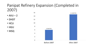
The document summarizes the expansion of the Panipat Refinery in 2007 which included the addition of new units: AVU-2, DHDT, HCU, HGU, and MSQ. It then discusses various solutions to optimize operations in these units by adjusting factors like stripping steam, overflash, and reflux ratio. Potential issues with flows in the DHDT and HCU units' wash water systems are identified and calculating pipe sizes and material balances in these systems are proposed as solutions.

Recommended
Recommended
More Related Content
What's hot
What's hot (20)
Similar to Panipat Refinery Report - Presentation (Summer Internship 2018)
Similar to Panipat Refinery Report - Presentation (Summer Internship 2018) (20)
More from Nibir Pawan
More from Nibir Pawan (7)
Recently uploaded
Recently uploaded (20)
Panipat Refinery Report - Presentation (Summer Internship 2018)
- 1. Panipat Refinery Expansion (Completed in 2007) • AVU – 2 • DHDT • HCU • HGU • MSQ 6 MMTPA 15 MMTPA 0 2 4 6 8 10 12 14 16 Before 2007 After 2007
- 4. Possible Solutions INCREASING THE STRIPPING STEAM THAT IS BEING SENT AT BOTTOM. Disadvantage: • Increase in the energy consumption. • Heavies carry over • Increase in the condensing duty • Risk of flooding
- 5. Possible Solutions INCREASING THE OVERFLASH. Disadvantage: 1.By increasing COT of Heater resulting Heater load increases. 2.Might lead to cracking/over cracking causing coke formation. 3.Lighter formation that cannot be tolerated. 4.Higher Over flash put lot more energy in furnace.
- 6. Possible Solutions DECREASING THE REFLUX RATIO OF NAPTHA. Disadvantage: 1.Has advantage of reduction in duty of condenser. 2.More stages are required to get the desired purity. 3.Not enough to cause a remarkable change in kerosene outlet temp.
- 9. Some of the calculation done through excel is being done and attached along: For crude temperature=125 o C 1.Taking the LVGO inlet temperature=165 O C Area=518 m 2 which is quite less than the available area.
- 10. Taking the LVGO inlet temperature=156 O C. Area used =765 m 2
- 11. Case-2 Increasing the crude inlet temperature to 126 OC Taking LVGO at 165 OC. Area used =709 m 2
- 12. Taking LVGO at 160OC.
- 13. Taking LVGO at 156OC.
- 15. Wash/Sour Water Systems • Wash Water (Pure/Treated Water) • Stripped Sour Water (SSW) from Sulphur Recovery Unit (SRU) • De-Mineralized Water • Boiler Feed Water (BFW) • RGC MP Steam Condensate from DHDT • Cooling Water (CW) • Service Water (SW) • Sour Water (Untreated Water from the plant) containing Sulphur, Nitrogen impurities
- 16. Why do we need Wash Water System? • Use Water Remover Level Controller
- 17. What was our Aim? • To show material balance among various Wash Water Sources and Wash water outlets. • To show the water carrying line sizes (from P&ID). • To show the various Pumps and Vessels, in use to transport and store the Water throughout the Panipat Refinery Expansion Project. • To recommend a solution to flow problem existing in DHDT and HCU Unit.
- 18. DHDT (Diesel Hydrotreating Unit) DHD T Wash Water SSW from SRU Wash Water Drum and Air fin Coolers 28tph RGC Turbine as MP Condensate 4tph Stripping Steam/Fe ed Stripper 5tph Sour Water Cold HP/MP Separator SRU (Hydrotreate d) 32tph Stripper Boot MP Condensate 5tph
- 24. AVU-2 Desalter Wash Water DM Water Desalter Water Vessel 30 tph SSW from SRU 30 tph Water in Crude Dissolved in Crude 10 tph Brine Desalter Water Vessel ETP 70 tph Column CDU Stripping Steam 32 tph VDU 7.5 tph Steam Ejector 37 tph Sour Water SRU (Un-Hydrotreated) 76.5 tph HCU Wash Water SSW from SRU Air Fin Coolers 17.7 m3 DM Water RGC Turbine as MP Condensate Fractionator Boot (Exception) Stripping Steam/Feed Stripper 2.2 m3 Sour Water Cold Flash Drum 17.7 m3 Stripper Boot 2.2 m3 MSQ NHT Wash Water Cold Condensate Air Fin Coolers 3 m3 Sour Water NHT Product Separator Boot SRU 3 m3 FCC GDS Wash Water Cold Condensate HDS Effluent Air Condenser 250 kg Sour Water HDS Separator Drum Boot SRU 250 kg HGU Wash Water BFW from Header Air Fin Coolers 7 tph Stripping Steam/Feed Stripper 0.285 tph Sour Water SRU 7.285 tph Summary
- 25. Solutions
- 26. References and Acknowledgement • Mr. Sandeep Mahajan, DGM • Mr. Sumit Kumar, PNE • Mr. Shubham Kumar, PNE • Mr. Satya Prakash Meena, PNE • IOCL PRE Manuals