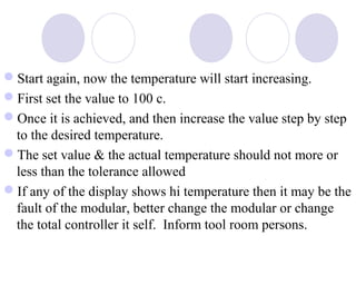
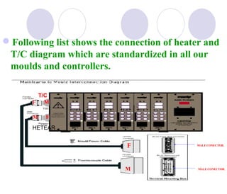
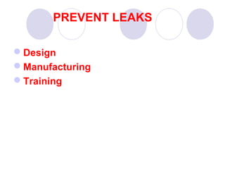
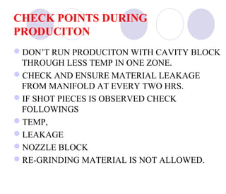
Downloaded 262 times
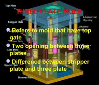
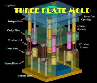
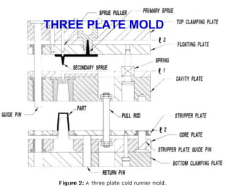
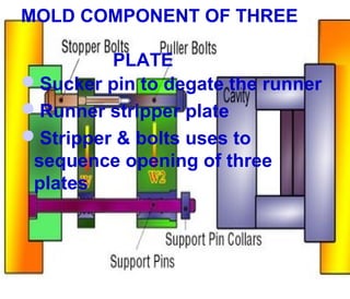

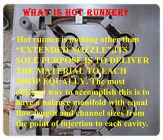


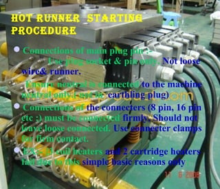


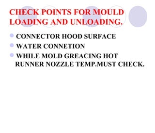


This document discusses three plate molds and hot runner systems. It explains that three plate molds have two openings between three plates and a top gate. It also describes the components of a three plate mold like sucker pins and stripper plates. The document then discusses hot runner systems, noting that they are like extended nozzles that deliver molten plastic evenly to each cavity. It provides procedures for starting up and checking hot runner systems, preventing leaks, and checking for issues during production.


![Basic of tool room and types of moulds [bharat jiyani]](https://cdn.slidesharecdn.com/ss_thumbnails/basicoftoolroomandtypesofmouldsbharatjiyani-170317122658-thumbnail.jpg?width=640&height=640&fit=bounds)


![Training of hot runner system [bharat jiyani]](https://cdn.slidesharecdn.com/ss_thumbnails/trainingofhotrunnersystembharatjiyani-170317121709-thumbnail.jpg?width=640&height=640&fit=bounds)


