Processing & Properties of Floor and Wall Tiles.pptx
Frame element
1. Frame Element Stiffness Matrices
CEE 421L. Matrix Structural Analysis
Department of Civil and Environmental Engineering
Duke University
Henri P. Gavin
Fall, 2012
Truss elements carry axial forces only. Beam elements carry shear forces
and bending moments. Frame elements carry shear forces, bending moments,
and axial forces. This document picks up with the previously-derived truss
and beam element stiffness matrices in local element coordinates and proceeds
through frame element stiffness matrices in global coordinates.
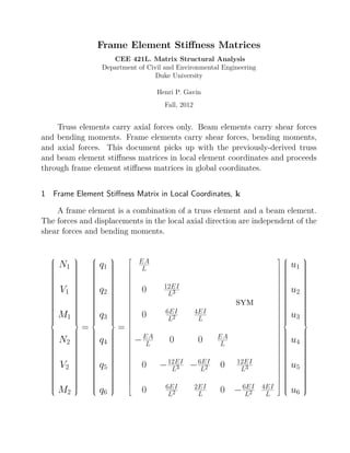
1 Frame Element Stiffness Matrix in Local Coordinates, k
A frame element is a combination of a truss element and a beam element.
The forces and displacements in the local axial direction are independent of the
shear forces and bending moments.
N1
V1
M1
N2
V2
M2
=
q1
q2
q3
q4
q5
q6
=
EA
L
0 12EI
L3
sym
0 6EI
L2
4EI
L
−EA
L 0 0 EA
L
0 −12EI
L3 −6EI
L2 0 12EI
L3
0 6EI
L2
2EI
L 0 −6EI
L2
4EI
L
u1
u2
u3
u4
u5
u6
2. 2 CEE 421L. Matrix Structural Analysis – Duke University – Fall 2012 – H.P. Gavin
2 Relationships between Local Coordinates and Global Coordinates: T
The geometric relationship between local displacements, u, and global dis-
placements, v, is
u1 = v1 cos θ + v2 sin θ u2 = −v1 sin θ + v2 cos θ u3 = v3
or, u = T v.
The equilibrium relationship between local forces, q, and global forces, f,
is
q1 = f1 cos θ + f2 sin θ q2 = −f1 sin θ + f2 cos θ q3 = f3
or, q = T f, where, in both cases,
T =
c s 0
−s c 0 0
0 0 1
c s 0
0 −s c 0
0 0 1
c = cos θ =
x2 − x1
L
s = sin θ =
y2 − y1
L
The coordinate transformation matrix, T, is orthogonal, T−1
= TT
.
CC BY-NC-ND H.P. Gavin
3. Frame Element Stiffness Matrices 3
3 Frame Element Stiffness Matrix in Global Coordinates: K
Combining the coordinate transformation relationships,
q = k u
T f = k T v
f = TT
k T v
f = K v
which provides the force-deflection relationships in global coordinates. The
stiffness matrix in global coordinates is K = TT
k T
K =
EA
L c2 EA
L cs −EA
L c2
−EA
L cs
+12EI
L3 s2
−12EI
L3 cs −6EI
L2 s −12EI
L3 s2
+12EI
L3 cs −6EI
L2 s
EA
L s2
−EA
L cs −EA
L s2
+12EI
L3 c2 6EI
L2 c +12EI
L3 cs −12EI
L3 c2 6EI
L2 c
4EI
L
6EI
L2 s −6EI
L2 c 2EI
L
EA
L c2 EA
L cs
+12EI
L3 s2
−12EI
L3 cs 6EI
L2 s
sym
EA
L s2
+12EI
L3 c2
−6EI
L2 c
4EI
L
CC BY-NC-ND H.P. Gavin
4. 4 CEE 421L. Matrix Structural Analysis – Duke University – Fall 2012 – H.P. Gavin
4 Frame Element Stiffness Matrices for Elements with End-Releases
Some elements in a frame may not be fixed at both ends. For example,
an element may be fixed at one end and pinned at the other. Or, the element
may be guided on one end so that the element shear forces at that end are zero.
Or, the frame element may be pinned at both ends, so that it acts like a truss
element. Such modifications to the frame element naturally affect the elements
stiffness matrix.
Consider a frame element in which a set of end-coordinates r are released,
and the goal is to find a stiffness matrix relation for the primary p retained
coordinates. The element end forces at the released coordinates, qr are all zero.
One can partition the element stiffness matrix equation as follows
qp
qr
kpp kpr
krp krr
up
ur
The element displacement coordinates at the released coordinates do not equal
the structural displacements at the collocated structural coordinates, since the
coordinates r are released. Since the element end forces at the released coor-
dinates are all zero (qr = 0), the element end displacements at the released
coordinates must be related to the displacements at the primary (retained)
coordinates as:
ur = −k−1
rr krpup
The element stiffness matrix equation relating qp and up is
qp = kpp − kprk−1
rr krp up
The rows and columns of the released element stiffness matrix corresponding
to the released coordinates, r, are set to zero. The rows and columns of the
released element stiffness matrix corresponding to the retained coordinates, p,
are [kpp − kprk−1
rr krp]. This is the element stiffness matrix that should assemble
into the structural coordinates collocated with the primary (retained) coordi-
nates p. The following sections give examples for pinned-fixed and fixed-pinned
frame elements. Element stiffness matrices for many other end-release cases
can be easily computed.
CC BY-NC-ND H.P. Gavin
5. Frame Element Stiffness Matrices 5
4.1 Pinned-Fixed Frame Element in Local Coordinates, k . . . (r = 3)
k =
EA
L 0 0 −EA
L 0 0
3EI
L3 0 0 −3EI
L3
3EI
L2
0 0 0 0
EA
L 0 0
sym
3EI
L3 −3EI
L2
3EI
L
4.2 Pinned-Fixed Frame Element in Global Coordinates, K = TT
kT
K =
EA
L c2 EA
L cs 0 −EA
L c2
−EA
L cs −3EI
L2 s
+3EI
L3 s2
−3EI
L3 cs −3EI
L3 s2
+3EI
L3 cs
EA
L s2
0 −EA
L cs −EA
L s2 3EI
L2 c
+3EI
L3 c2
+3EI
L3 cs −3EI
L3 c2
0 0 0 0
EA
L c2 EA
L cs EI
L2 s
+3EI
L3 s2
−3EI
L3 cs
sym
EA
L s2
−3EI
L2 c
3EI
L3 c2
3EI
L
CC BY-NC-ND H.P. Gavin
6. 6 CEE 421L. Matrix Structural Analysis – Duke University – Fall 2012 – H.P. Gavin
4.3 Fixed-Pinned Frame Element in Local Coordinates, k . . . (r = 6)
k =
EA
L 0 0 −EA
L 0 0
3EI
L3
3EI
L2 0 −3EI
L3 0
3EI
L 0 −3EI
L2 0
EA
L 0 0
sym
3EI
L3 0
0
4.4 Fixed-Pinned Frame Element in Global Coordinates, K = TT
kT
K =
EA
L c2 EA
L cs −3EI
L2 s −EA
L c2
−EA
L cs 0
+3EI
L3 s2
−3EI
L3 cs −3EI
L3 s2
+3EI
L3 cs
EA
L s2 3EI
L2 c −EA
L cs −EA
L s2
0
+3EI
L3 c2
+3EI
L3 cs −3EI
L3 c2
3EI
L
3EI
L2 s −3EI
L2 c 0
EA
L c2 EA
L cs 0
+3EI
L3 s2
−3EI
L3 cs
sym
EA
L s2
0
+3EI
L3 c2
0
CC BY-NC-ND H.P. Gavin
7. Frame Element Stiffness Matrices 7
5 Notation
u = Element deflection vector in the Local coordinate system
q = Element force vector in the Local coordinate system
k = Element stiffness matrix in the Local coordinate system
... q = k u
T = Coordinate Transformation Matrix
... T−1
= TT
v = Element deflection vector in the Global coordinate system
... u = T v
f = Element force vector in the Global coordinate system
... q = T f
K = Element stiffness matrix in the Global coordinate system
... K = TT
k T
d = Structural deflection vector in the Global coordinate system
p = Structural load vector in the Global coordinate system
Ks = Structural stiffness matrix in the Global coordinate system
... p = Ks d
Local Global
Element Deflection u v
Element Force q f
Element Stiffness k K
Structural Deflection - d
Structural Loads - p
Structural Stiffness - Ks
For frame element stiffness matrices including shear deformations, see:
J.S. Przemieniecki, Theory of Matrix Structural Analysis, Dover Press, 1985.
(... a steal at $12.95)
CC BY-NC-ND H.P. Gavin